# MXA-200

# IoT Gateway

# User’s Manual

![Exterior view of a black ADLINK network device with labeled ports and connectors (no readable text beyond labels)](.mxa-200-50m-44a00-1000-10/2347ba81b7f2d1902f0cc0db1ad4166c5620055b4ec4f07baadd09a6ea31c370.jpg)

Manual Rev.: 1.0

Revision Date: August 20, 2024

Part No: 50M-44A00-1000

Revision History

<table><tr><td>Revision</td><td>Release Date</td><td>Description of Change(s)</td></tr><tr><td>1.0</td><td>2024-08-20</td><td>Initial release</td></tr></table>

# Preface

# Copyright © 2024 ADLINK Technology Inc.

This document contains proprietary information protected by copyright. All rights are reserved. No part of this manual may be reproduced by any mechanical, electronic, or other means in any form without prior written permission of the manufacturer.

# Disclaimer

The information in this document is subject to change without prior notice in order to improve reliability, design, and function and does not represent a commitment on the part of the manufacturer.

In no event will the manufacturer be liable for direct, indirect, special, incidental, or consequential damages arising out of the use or inability to use the product or documentation, even if advised of the possibility of such damages.

ADLINK is committed to fulfill its social responsibility to global environmental preservation through compliance with the European Union's Restriction of Hazardous Substances (RoHS) directive and Waste Electrical and Electronic Equipment (WEEE) directive. Environmental protection is a top priority for ADLINK. We have enforced measures to ensure that our products, manufacturing processes, components, and raw materials have as little impact on the environment as possible. When products are at their end of life, our customers are encouraged to dispose of them in accordance with the product disposal and/or recovery programs prescribed by their nation or company.

![Symbol of a trash bin crossed with a diagonal line and a horizontal bar below (no text or labels)](.mxa-200-50m-44a00-1000-10/528fe13d01059ed3d7250d61ecd3ad43ee0c75450d1020a20f0e22c90d82cf53.jpg)

Battery Labels (for products with battery)
![Symbol of a trash bin crossed out by two diagonal lines (no text or numbers present)](.mxa-200-50m-44a00-1000-10/378c10180af1a8d9b739e047e6869c1d0d1e4035cf364ad8d49474ce3851958f.jpg)

![Recycling symbol icon with three chasing arrows inside a square frame (no text or labels)](.mxa-200-50m-44a00-1000-10/bf1fc8f71d117e350bb082c878d2296a668c76f9d90bfb74beda0555410d22e2.jpg)

Li-ion

![RECYCLE\nRBRC\nLi-ion\n7.800.822.8837](.mxa-200-50m-44a00-1000-10/bc02eccb639b0c9d7c7af377e5e3e96d9116072c244a4233753483e348298aef.jpg)

![Abstract geometric pattern with interlocking black and white shapes (no text or symbols)](.mxa-200-50m-44a00-1000-10/231e8d0a0cefb704c2515ea6fbd6eb1f04a48d3d94c337d2f73433d838c65fc5.jpg)

ᘄ㟁ụㄳᅇᨲ

# California Proposition 65 Warning

![This image displays a standard yellow triangular warning sign with a thick black border. Inside the triangle is a centered black exclamation point.](.mxa-200-50m-44a00-1000-10/bb628d8d84c5fd262cac21c9aa8d613d659cffe8c6d3177a48a388aa69e82c45.jpg)

WARNING: This product can expose you to chemicals including acrylamide, arsenic, benzene, cadmium, Tris(1,3-dichloro-2-propyl)phosphate (TDCPP), 1,4-Dioxane, formaldehyde, lead, DEHP, styrene, DINP, BBP, PVC, and vinyl materials, which are known to the State of California to cause cancer, and acrylamide, benzene, cadmium, lead, mercury, phthalates, toluene, DEHP, DIDP, DnHP, DBP, BBP, PVC, and vinyl materials, which are known to the State of California to cause birth defects or other reproductive harm. For more information go to www.P65Warnings.ca.gov.

# Trademarks

Product names mentioned herein are used for identification purposes only and may be trademarks and/or registered trademarks of their respective companies.

# Conventions

Take note of the following conventions used throughout this manual to make sure that users perform certain tasks and instructions properly.

![The image displays a simple icon featuring a white document or file symbol with a folded top-right corner. Faint horizontal grey lines are visible on the document, suggesting text. A large, bold red checkmark is superimposed over the left side of the document. The icon is enclosed within a thin black border.](.mxa-200-50m-44a00-1000-10/d9fd1bacab7728a9615fe4b22638bbe931c9d897b60382ea79e32643c5162abf.jpg)
NOTE:

Additional information, aids, and tips that help users perform tasks.

![The image shows a yellow triangular warning sign with a thick black border. Centered inside the triangle is a large black exclamation point. The background surrounding the sign is white.](.mxa-200-50m-44a00-1000-10/412ab18b0d434e4474e906004b92280c5f6e195b90e636aa0654cdf27186ebb1.jpg)
CAUTION:

Information to prevent minor physical injury, component damage, data loss, and/or program corruption when trying to complete a task.

![The image displays a red triangular warning sign. Inside the triangle, centered, is a large white exclamation point.](.mxa-200-50m-44a00-1000-10/e71471f878bc7661dee1d44f4ed3006483f5dbd1486ea5d70236f6e1e2a82dcb.jpg)
WARNING:

Information to prevent serious physical injury, component damage, data loss, and/or program corruption when trying to complete a specific task.

# Table of Contents

# Preface ......... iii

# List of Figures ......... ... vii

# 1 Introduction ........

1.1 Features... 1
1.2 Packing List .... 2
1.3 Optional Accessories .... 2
1.4 Specifications..... 3
1.5 Functional Block Diagram... 5
1.6 Mechanical Drawings...... 6
1.7 I/O Connectors..... 11

# 2 Getting Started ..... . 17

2.1 Unpacking the MXA-200.. 17
2.2 Connecting DC Power ... 18

# A Appendix: Debian Linux OS...... .. 21

A.1 Hardware Setup.. 21
A.2 Connecting and Logging in via SSH .. 2 2
A.3 LED Function .... 23
A.4 Serial Port Configuration.. 23
A.5 Network Settings.. 24
A.6 5G/4G/LTE Module Configuration ... 25
A.7 Wi-Fi Configuration and Connection.... 27

# B Appendix: Accessory Installation...... . 29

B.1 Wi-Fi Module.... 29
B.2 4G Module ... . 35
B.3 5G Module ... 40

Important Safety Instructions....... .. 45

Consignes de Sécurité Importantes ........ .. 47

Getting Service ........ .... 51

# List of Figures

Figure 1-1: Functional Block Diagram.. . 5
Figure 1-2: MXA-200 Dimensions.. .. 6
Figure 1-3: DIN Rail Mount 1 . 7
Figure 1-4: DIN Rail Mount 2 . . 8
Figure 1-5: Wall Mount 1.. . 9
Figure 1-6: Wall Mount 2.. . 9
Figure 1-7: Wall Mount 3... .. 10
Figure 1-8: Front View .. . 11
Figure 1-9: Side View... . 11
Figure 1-10: DC Power Input .. . 13
Figure 1-11: COM Port Pin Definition . .. 15

This page intentionally left blank.

# 1 Introduction

The MXA-200 IoT Energy Gateway provides communication conversion between different Ethernet or serial-based protocols allowing for wider integration of devices into a network with the ability to send data to the cloud. It is designed to work under a large variety of applications such as monitoring energy consumption, electric vehicle charging control and monitoring, renewable energy monitoring, and smart manufacturing.

The MXA-200 is an i.MX8M Plus based high-performance IoT gateway with a Quad Core processor open platform design, two RS-232/422/485 isolated serial ports, two 10/100/1000 Ethernet ports, two USB 3.0 port and an operating temperature range of -20\~70°C. It offers two M.2 slots for integrating Wi-Fi/4G/5G modules. The MXA-200 enables system integrators to develop applications precisely for renewable energy, EV charging, smart cities and factories that require massive data collection, a cloud-based application and video related monitoring solutions.

# 1.1 Features

 NXP i.MX8M Plus Cortex A53 Quad Core 1.8GHz
 LPDDR4 2GB RAM, 32GB eMMC for system storage
 2x RS-232/422/485 isolated serial ports
 2x 10/100/1000 Ethernet ports
 1x M.2 E-key for Wi-Fi
 1x M.2 B-key for 5G or 4G/LTE
 Operating Temperature: $\angle 0 ^ { \circ } \mathsf { C }$ to $7 0 ^ { \circ } \mathsf { C }$

# 1.2 Packing List

Before unpacking, check the shipping carton for any damage. If the shipping carton and/or contents are damaged, inform your dealer immediately. Retain the shipping carton and packing materials for inspection. Obtain authorization from your dealer before returning any product to ADLINK. Ensure that the following items are included in the package.

 1x MXA-200 IoT Gateway
 DIN rail mount kit with 2x flat head screws
 Wall mount kit with 4x pan head screws
 Quick Start Guide

# 1.3 Optional Accessories

 24V/90W power adapter (P/N: 31-62187-1000-A0)

# 1.4 Specifications

<table><tr><td>Model</td><td>MXA-200</td></tr><tr><td colspan="2">System</td></tr><tr><td>Processor</td><td>i.MX8M Plus ARM Cortex A53 Quad Core 1.8GHz</td></tr><tr><td>Memory</td><td>LPDDR4 2/4GB</td></tr><tr><td>Main Storage</td><td>32/64 GB eMMC</td></tr><tr><td>Storage Slot</td><td>1x microSD</td></tr><tr><td>TPM</td><td>TPM2.0</td></tr><tr><td>RTC</td><td>Monthly difference max.180 sec.</td></tr><tr><td>WDT</td><td>Supported</td></tr><tr><td colspan="2">I/O Interfaces</td></tr><tr><td>Ethernet</td><td>2x GbE</td></tr><tr><td>Serial Ports</td><td>2x RS-232/422/485, 4-wire</td></tr><tr><td>USB</td><td>2x USB 3.0 Type-A</td></tr><tr><td>Display</td><td>1x HDMI</td></tr><tr><td>Wi-Fi/BT</td><td>1x M.2 2230 E-key</td></tr><tr><td>Expanded I/F</td><td>1x M.2 2242 B-key (USB 3.0) for 5G or 4G/LTE</td></tr><tr><td colspan="2">Mechanical</td></tr><tr><td>Dimensions</td><td>110.90 (L) x 40 (W) x 131.4 (H) mm</td></tr><tr><td>Mounting</td><td>DIN rail kit / wall mount kit</td></tr><tr><td>Housing</td><td>Metal</td></tr><tr><td>Cooling</td><td>Fanless</td></tr><tr><td colspan="2">Power Supply</td></tr><tr><td>DC Input</td><td>12-24V DC</td></tr><tr><td colspan="2">Environmental</td></tr><tr><td>Operating Temperature</td><td>-20°C to 70°C</td></tr><tr><td>Storage Temperature</td><td>-25°C to 80°C</td></tr><tr><td>Humidity</td><td>approx. 95% @ 40°C (non-condensing)</td></tr><tr><td>Vibration Resistance</td><td>1. Test Standard: Referenced from IEC 60068-2-642. Test Mode: Random wave3. Frequency: 5-500 Hz4. Acceleration: 2 Grms5. Direction: X, Y, Z axis6. Duration: 60 min/axis</td></tr><tr><td>Shock Resistance</td><td>1. Test Standard: Referenced from IEC 60068-2-272. Acceleration: 20G3. Pulse width: 11ms4. System condition: Operation mode5. Test faces: -X,-Y,-Z, X, Y, Z axis6. Test times: 3 times per axis</td></tr><tr><td colspan="2">Certifications</td></tr><tr><td>EMC</td><td>CE / UKCA / RCM / KC / FCCEN/IEC 61000-6-4:2019; EN/IEC 61000-6-2:201947 CFR FCC Part 15 Subpart B, class B</td></tr><tr><td>UL</td><td>IEC 62368-1:2014; EN 62368-1:2014+A11:2017UL 61010-1; CSA C22.2 No.61010-1UL 61010-2-201; CSA C22.2 No.61010-2-201</td></tr></table>

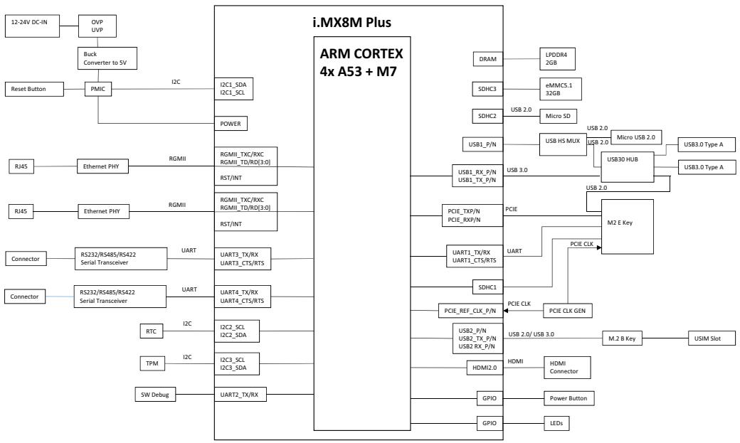
# 1.5 Functional Block Diagram

![The provided block diagram illustrates the system architecture of an **i.MX8M Plus** module (featuring an **ARM CORTEX 4x A53 + M7** processor).\n\n**Power and Initialization:**\n*   **12-24V DC-IN** connects to **OVP UVP**, which connects to **Buck Converter to 5V**.\n*   **Reset Button** connects to **PMIC**.\n*   **PMIC** connects via **I2C** to **I2C1_SDA / I2C1_SCL** and connects to **POWER**.\n\n**Ethernet and Serial Interfaces (Left Side):**\n*   Two **RJ45** blocks connect to **Ethernet PHY** blocks, which connect via **RGMII** to **RGMII_TX/RXC / RGMII_TD/RD(3:0) / RST/INT** blocks.\n*   Two **Connector** blocks connect to **RS232/RS485/RS422 Serial Transceiver** blocks.\n    *   One connects via **UART** to **UART3_TX/RX / UART3_CTS/RTS**.\n    *   One connects via **UART** to **UART4_TX/RX / UART4_CTS/RTS**.\n*   **RTC** connects via **I2C** to **I2C2_SCL / I2C2_SDA**.\n*   **TPM** connects via **I2C** to **I2C3_SCL / I2C3_SDA**.\n*   **SW Debug** connects to **UART2_TX/RX**.\n\n**Memory and Storage (Top Right):**\n*   **DRAM** connects to **LPDDR4 2GB**.\n*   **SDHC3** connects to **eMMC5.1 32GB**.\n*   **SDHC2** connects via **USB 2.0** to **Micro SD**.\n\n**USB Interfaces (Top Right):**\n*   **USB1_P/N** connects via **USB 2.0** to **USB HS MUX**, which connects via **USB 2.0** to **Micro USB 2.0**.\n*   **USB1_P/N** connects via **USB 2.0** to **USB30 HUB**.\n*   **USB1_RX_P/N** connects via **USB 3.0** to **USB30 HUB**.\n*   **USB30 HUB** connects via **USB 2.0** to **USB3.0 Type A**.\n*   **USB1_RX_P/N** connects via **USB 3.0** to **USB3.0 Type A**.\n\n**PCIe and M.2 Interfaces (Middle/Bottom Right):**\n*   **PCIE_TXP/N** and **PCIE_RXP/N** connect to **PCIE**, which connects to **M2 E Key**.\n*   **SDHC1** connects to **PCIE CLK**.\n*   **PCIE_REF_CLK_P/N** connects to **PCIE CLK**.\n*   **PCIE CLK** connects to **PCIE CLK GEN**, which connects to **PCIE CLK** (connected to **M2 E Key**).\n*   **UART1_TX/RX / UART1_CTS/RTS** connects to a label **UART**.\n*   **USB2_P/N / USB2_TX_P/N / USB2_RX_P/N** connects via **USB 2.0/USB 3.0** to **M.2 B Key**, which connects to **USIM Slot**.\n\n**Other Outputs (Bottom Right):**\n*   **HDMI2.0** connects to **HDMI**, which connects to **HDMI Connector**.\n*   **GPIO** connects to **Power Button**.\n*   **GPIO** connects to **LEDs**.](.mxa-200-50m-44a00-1000-10/660222b02aaf5f0a69266415b6fc26ba9b93e6d3785acd7ef6f95acd7a833d5d.jpg)

Figure 1-1: Functional Block Diagram

# 1.6 Mechanical Drawings

![The image shows a standard icon of a document or piece of paper with a folded top-left corner and faint horizontal lines, overlaid with a large red checkmark.](.mxa-200-50m-44a00-1000-10/bcf81a3d02e761396f810face9b9f475ffbbca9ca3d4104e453424cd89165910.jpg)
NOTE:

All dimensions are in millimeters unless noted.

# 1.6.1 Dimensions
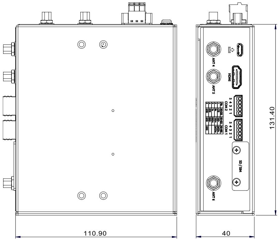
![110.90\n40\n131.40](.mxa-200-50m-44a00-1000-10/e86834e7e55bc97c95f2c32d5143d2fb6e641c71bc82a4723841b2921b5fd355.jpg)

Figure 1-2: MXA-200 Dimensions

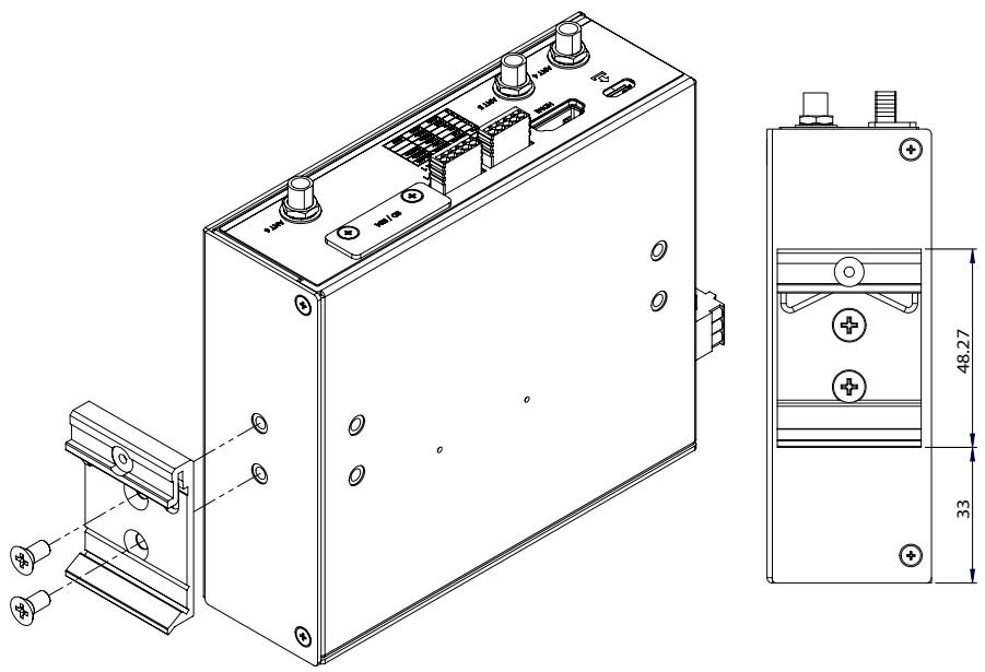
# 1.6.2 DIN Rail Mounting

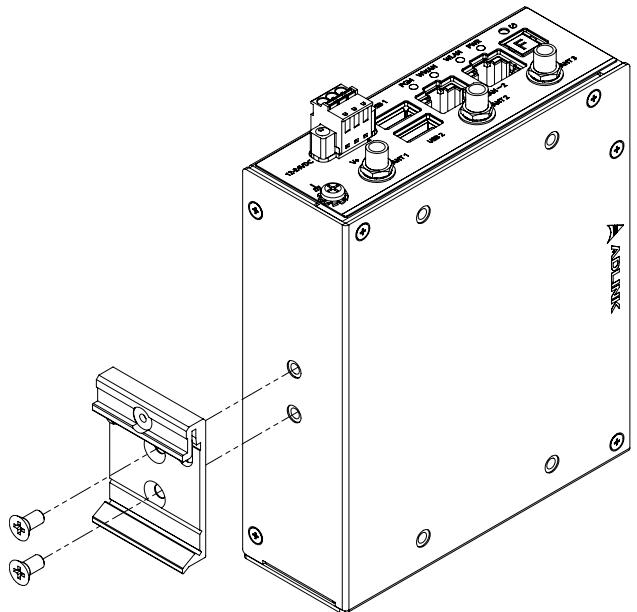
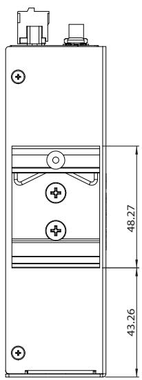
The DIN rail mount can be attached to the MXA-200 with two screws included in the wall mounting kit.
![Technical diagram of an electronic device with labeled components and mounting points, including a zoomed-in view detail.](.mxa-200-50m-44a00-1000-10/0fffa78458cfd3dbe79254f691eb2a880ad90216636aca704715487d0fde855d.jpg)

![48.27\n43.26](.mxa-200-50m-44a00-1000-10/7ccd4a66f98a4b73f0fdce7dafdeb5ddbbc8a5f0071714e54d62da5d89f90379.jpg)

Figure 1-3: DIN Rail Mount 1

![Technical diagram of an electronic device with labeled components and dimensional annotations](.mxa-200-50m-44a00-1000-10/532b38277e5886f1b996d1ecaa556739dfc9fceb1a3561c7749ce3e2ca92d974.jpg)

Figure 1-4: DIN Rail Mount 2

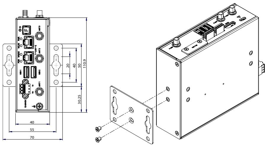
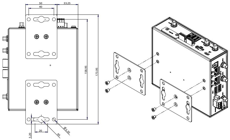
# 1.6.3 Wall Mounting

Each wall mount bracket can be attached to the MXA-200 with two screws included in the wall mounting kit.
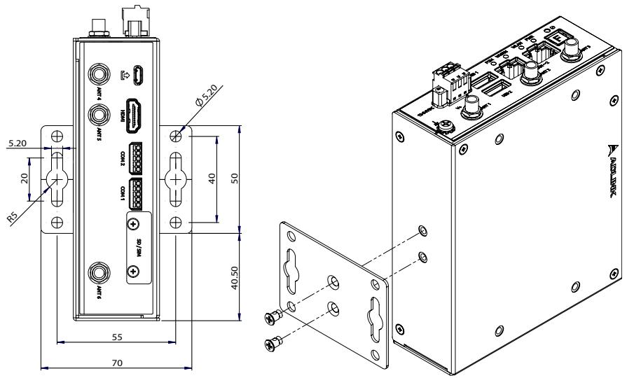
![5.20\n20\nR5\n9.1MP\n1.1MP\nHDD\n3MDD\n1MDD\nHDD/GB\nØ5.20\n40\n50\n40.50\n55\n70](.mxa-200-50m-44a00-1000-10/f16712d3ba4c6c932f1b18314c0edf1c21a4bc8fad48ee6a8480e14bd7c3db61.jpg)

Figure 1-5: Wall Mount 1

![AMT2\nL-A1-1\nAMT2\nUB1\nAMT1\n30.25\n40\n55\n70\n20\n40\n50\n110.9](.mxa-200-50m-44a00-1000-10/676f955cb83236992a368fe15438d6fc8a21be86608ca3ee45d4eff551e4e857.jpg)

Figure 1-6: Wall Mount 2

![50\n40\n33.25\n158.95\n173.95\n5.20\n20\nØ3.20\nR5](.mxa-200-50m-44a00-1000-10/130135d2daec7e41c8e9066d291b41de41ea8120e0047af3a350d15230fbcf08.jpg)

Figure 1-7: Wall Mount 3

# 1.7 I/O Connectors
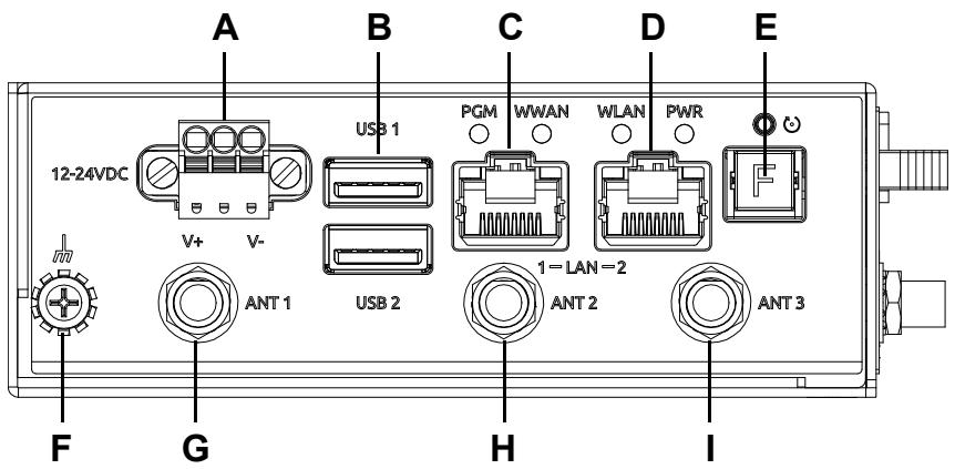
![A\nB\nC\nD\nE\n12-24VDC\nV+\nV-\nUSB 1\nPGM WWAN WLAN PWR\nF\nG\nANT 1\nUSB 2\n1=LAN=2\nANT 2\nANT 3\nH\nI](.mxa-200-50m-44a00-1000-10/194b5ab695ec5c56588759ac470242fefedff2b3de2c69bf246e02cff843eb55.jpg)

Figure 1-8: Front View

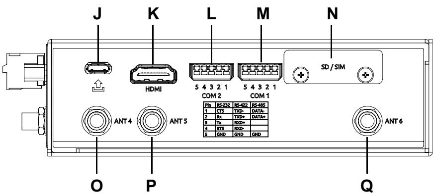
![J K L M N\nHDMI 5 4 3 2 1 5 4 3 2 1 COM 2 COM 1 SD / SIM\nANT 4 ANT 5 Ph RS-232 RS-422 RS-485\n1 CTS TXD DATA+\n2 Rx TXD DATA+\n3 Tx RXD\n4 RTS RXD\n5 GND GND GND\nANT 6\nO P Q](.mxa-200-50m-44a00-1000-10/edbb279496cf146aafc0ce34208efb581597da230d7fc4cc973946e36da448d7.jpg)

Figure 1-9: Side View

<table><tr><td>Item</td><td>Description</td></tr><tr><td>A</td><td>DC power input</td></tr><tr><td>B</td><td>USB 3.0 Type-A</td></tr><tr><td>C, D</td><td>Gigabit Ethernet (GbE, RJ45)</td></tr><tr><td>E</td><td>Function button</td></tr><tr><td>F</td><td>Ground screw</td></tr><tr><td>G, H, I, O, P, Q</td><td>Antenna connector (optional for Wi-Fi/4G/5G/GPS)</td></tr><tr><td>J</td><td>Micro USB Connector</td></tr><tr><td>K</td><td>HDMI</td></tr><tr><td>L, M</td><td>RS-232/422/485, 4-wire</td></tr><tr><td>N</td><td>microSD and SIM slot</td></tr></table>

Table 1-1: I/O Connector Legend

<table><tr><td>LED</td><td>Description</td></tr><tr><td>PWR LED</td><td>The LED will light up when the system is powered.</td></tr><tr><td>WLAN LED</td><td>When a Wi-Fi module is installed, the LED will light up after the system loads, otherwise the LED will not light up.</td></tr><tr><td>WWAN LED</td><td>When a 5G/4G/LTE module is installed, the LED will light up after the system loads, otherwise the LED will not light up.</td></tr><tr><td>PGM LED</td><td>The LED will light up when flashing the BSP to the eMMC via an SD card.</td></tr></table>

Table 1-2: I/O Connector Legend

# 1.7.1 DC Power Input

![Technical line drawing of a mechanical component with three circular ports and three side brackets (no text or symbols)](.mxa-200-50m-44a00-1000-10/3479ed3812165a02950183c632b0cec0f7f53359d7f967354d21ce8152b6c3d1.jpg)

Figure 1-10: DC Power Input

<table><tr><td>Pin</td><td>Signal</td></tr><tr><td>1</td><td>V+ (DC_IN)</td></tr><tr><td>2</td><td>GND</td></tr><tr><td>3</td><td>V-</td></tr></table>

# 1.7.2 USB 3.0 Ports

The USB 3.0 Type-A ports support are compatible with SuperSpeed, Hi-Speed, full-speed and low-speed USB devices, with support for multiple boot devices, including USB flash, USB external HDD, and USB CD-ROM drivers, and boot priority and boot device configured in BIOS.

# 1.7.3 Gigabit Ethernet Ports

There are two Gigabit Ethernet (GbE) ports on the front panel with two MAC address. Either port can be used for connecting to a host PC

 LAN1: The default is DHCP
 LAN2: The default static IP address is 192.168.50.2

# 1.7.4 Reboot Button

Pressing the reboot button will cause the system to reboot.

# 1.7.5 Function Key

Restore the MXA-200 to factory default settings by pressing the function button until the device reboots.

<table><tr><td>Item</td><td>Default Value</td></tr><tr><td>username</td><td>root</td></tr><tr><td>password</td><td>adlink</td></tr><tr><td>COM Port 1</td><td>RS-485/9600/N/8/1</td></tr><tr><td>COM Port 2</td><td>RS-485/9600/N/8/1</td></tr><tr><td>LAN 1</td><td>DHCP</td></tr><tr><td>LAN 2</td><td>Static IP:192.168.50.2</td></tr><tr><td>WiFi</td><td>▸ Disconnect WiFi network connection▸ Clean all parameters</td></tr><tr><td>Cellular (optional)</td><td>▸ Disconnect cellular network connection▸ Clean all parameters</td></tr></table>

# 1.7.6 Antenna Ports

Antenna ports ANT1-6 support the functions listed in Appendix B: Accessory Installation on page 29.

# 1.7.7 HDMI Connector

An HDMI Type-A socket is provided to connect a monitor to the system.

# 1.7.8 Micro-SIM Slot

Insert a micro-SIM card into the slot. Make sure it is properly aligned and inserted all the way. Once the card is inserted, the MXA-200 can connect to a cellular network and access the Internet.

# 1.7.9 COM Port Connectors

The MXA-200 provides two COM ports through 5-pin connectors. The COM1 & COM2 ports support RS-232/422/485 modes.

![This is a black-and-white line drawing of a rectangular module or battery pack. Inside an outer rectangular casing, there are two horizontal rows of components. The top row features five circles arranged side-by-side. The bottom row features five rectangles arranged side-by-side directly below the circles. Vertical lines connect each circle to the corresponding rectangle beneath it.](.mxa-200-50m-44a00-1000-10/0e1e630a8f316c295180d3e14625a53972773bc9098da29d84e198a462e731c5.jpg)
54321

Figure 1-11: COM Port Pin Definition

<table><tr><td rowspan="2">Pin</td><td colspan="3">Signal</td></tr><tr><td>RS-232</td><td>RS-422</td><td>RS-485</td></tr><tr><td>1</td><td>CTS</td><td>TXD-</td><td>DATA-</td></tr><tr><td>2</td><td>Rx</td><td>TXD+</td><td>DATA+</td></tr><tr><td>3</td><td>Tx</td><td>RXD+</td><td></td></tr><tr><td>4</td><td>RTS</td><td>RXD-</td><td></td></tr><tr><td>5</td><td>GND</td><td>GND</td><td>GND</td></tr></table>

Table 1-3: 5-pin Signal Function of COM Ports

# 1.7.10 microSD Slot

Insert a microSD card into the slot for additional storage.

This page intentionally left blank.

# 2 Getting Started

# 2.1 Unpacking the MXA-200

Ensure that the following items are included in the package. If any items are missing, contact your sales representative for assistance.

 MXA-200
 DIN rail mount kit with 2x flat head screws
 Wall mount kit with 4x pan head screws
 Quick Start Guide

![The image displays a warning label featuring a red equilateral triangle with a black exclamation point in the center. Below the triangle is a black rectangle containing the word 'WARNING:' in white capital letters.](.mxa-200-50m-44a00-1000-10/c23c1dafed7103105e188c4227238fc84a93800a72c762831a42a3c2b1ae052c.jpg)

Before unpacking, check the shipping carton for any damage. If the shipping carton and/or contents are damaged, inform your dealer immediately. Retain the shipping carton and packing materials for inspection. Obtain authorization from your dealer before returning any product to ADLINK.

# Déballage de la MXA-200

Assurez-vous que les éléments suivants sont inclus dans le colis. Si des éléments sont manquants, veuillez contacter votre représentant commercial pour obtenir de l'aide.

 MXA-200
 Kit de montage sur rail DIN avec 2 vis à tête plate
 Kit de montage mural avec 4 vis à tête cylindrique
 Guide de Démarrage Rapide

![The image displays a maroon triangular warning sign featuring a large white exclamation point in its center. Directly below the triangle, the word 'WARNING:' is printed in white capital letters against a black background.](.mxa-200-50m-44a00-1000-10/892794ef7cda34c97690d7c2399a26e3c5f2de8931c1ed611fcc3121655387d3.jpg)

AVERTISSEMENT: Avant de déballer, vérifiez l'emballage d'expédition pour tout dommage. Si l'emballage d'expédition et/ou le contenu sont endommagés, informez immédiatement votre revendeur. Conservez l'emballage d'expédition et les matériaux d'emballage pour inspection. Obtenez l'autorisation de votre revendeur avant de retourner tout produit à ADLINK.

# 2.2 Connecting DC Power

DC power source output rating:

 Voltage: 12 to 24 VDC
 Current: 5A to 2.5A minimum

Follow these steps to connect power to the MXA-200:

1 Before turning on the power source, connect the positive and negative wires from a 12 to 24V DC power source to the terminal block.
2. Turn on the power source. If the power was connected correctly, the front panel green PWR LED will light up.

![The image displays a warning sign featuring a dark red triangle with a white exclamation point in the center, positioned directly above a white rectangular box containing the word 'WARNING' in black capital letters.](.mxa-200-50m-44a00-1000-10/37dc99ddd47bc66df2fb0ae6a1469995cdd568544525a99d2e711b216e215a70.jpg)

 Only use an IEC or UL certified power source.
 The maximum operating altitude is 5000m whose output meets LPS and SELV (ES1) circuits.

If the MXA-200 needs to be shut down, turn off the power source.

To remove the power wires, use a flat head screwdriver to push the orange slots on the terminal block and then pull out the wires.

![The image displays a yellow triangular warning sign with a black border. Centered inside the triangle is a large black exclamation point. Directly below the triangle, the word 'CAUTION' is printed in black capital letters.](.mxa-200-50m-44a00-1000-10/d0af4810262f623d283196f8946e9ed1e03135d70623823159a24895ba10bd15.jpg)

 Ensure the power source is turned off before connecting or removing the power wires.
Before providing DC power to the apparatus, ensure the voltage and polarity provided are compatible with the DC input. Improper input voltage and/or polarity can be responsible for system damage.

# Connexion de l'alimentation CC

Valeur nominale de sortie de la source d'alimentation CC:

 Tension: 12 à 24 VCC
 Courant: 5A à 2,5A minimum

Suivez ces étapes pour connecter l'alimentation à l'MXA-200:

1 Avant d'allumer la source d'alimentation, connectez les fils positifs et négatifs d'une source d'alimentation de 12 à 24 V CC au bornier.
2. Allumez la source d’alimentation. Si l'alimentation a été correctement connectée, la LED verte PWR du panneau avant s'allumera.

![The image shows a standard safety warning sign. It features a red equilateral triangle pointing upward with a black exclamation point in the center. Below the triangle, the text 'WARNING:' is printed in bold, black capital letters.](.mxa-200-50m-44a00-1000-10/876bedf8b8d69444b1d84804cc9050f715f019793a1c46a9b4040327376a2585.jpg)

Utilisez uniquement une source d'alimentation certifiée IEC ou UL.
 L'altitude maximale de fonctionnement est de 5 000 m dont la sortie répond aux circuits LPS et SELV (ES1).

Si l'MXA-200 doit être arrêté, coupez la source d'alimentation.

Pour retirer les fils d'alimentation, utilisez un tournevis à tête plate pour pousser les fentes orange du bornier puis retirez les fils.

![A yellow triangular warning sign with a black exclamation mark centered inside. Below the triangle, the word 'CAUTION' is written in black capital letters.](.mxa-200-50m-44a00-1000-10/b16b5815773680652a88ddbb73828e1236b8ff2fae8d7f4f9eaa52e151b54cad.jpg)

 Assurez-vous que la source d'alimentation est éteinte avant de connecter ou de retirer les fils d'alimentation.
 Avant de fournir une alimentation CC à l'appareil, assurez-vous que la tension et la polarité fournies sont compatibles avec l'entrée CC. Une tension d'entrée et/ou une polarité incorrecte peuvent être responsables d'endommagements du système.

This page intentionally left blank.

# Appendix A Debian Linux OS

Debian Linux is used as the MXA-200 operating system for system integrators to develop customization applications.This appendix includes information on the following items.

 Hardware Setup
 Connecting and Logging in via SSH
 LED Function
 Serial Port Configuration
 Network Settings
 5G/4G/LTE Module Configuration
 WiFi Configuration and Connection

# A.1 Hardware Setup

1. LAN1 (DHCP) connects to the network. LAN2 (Static IP) connects to the MXA-200 via SSH.
2. Connect the MXA-200 to a 12-24V DC power supply.
3. The MXA-200 will power on automatically.

# A.2 Connecting and Logging in via SSH

1. Set the network domain of the host computer that will be connected to the MXA-200 to 192.168.50.xx.
2. Open Putty on the host computer and enter the IP address of the MXA-200: 192.168.50.2.

![PuTTY Configuration\nCategory:\nSession\nLogging\nTerminal\nKeyboard\nBell\nFeatures\nWindow\nAppearance\nBehaviour\nTranslation\nSelection\nColours\nConnection\nData\nProxy\nTelnet\nRlogin\nSSH\nSerial\nBasic options for your PuTTY session\nSpecify the destination you want to connect to\nHost Name (or IP address)\nPort\n192.168.50.2\n22\nConnection type:\nRaw  Telnet  Rlogin  SSH  Serial\nLoad, save or delete a stored session\nSaved Sessions\nDefault Settings\nLoad\nSave\nDelete\nClose window on exit:\nAlways  Never  Only on clean exit\nOpen\nAbout    Help    Cancel](.mxa-200-50m-44a00-1000-10/b44a9da7706af7d80be451e01ed6b4fb37523e7731d1d913d3d295bc6634c41c.jpg)

3. Log in with the username (root) and password (adlink).

4. You have successfully connected to the MXA-200.

![The image displays two computer icons stacked vertically against a white background. Each icon depicts a desktop computer with a monitor showing a blue screen and a tower unit below it. A yellow starburst shape connects the two computer icons, suggesting a network or link between them. A thin vertical blue bar runs along the far left edge of the image.](.mxa-200-50m-44a00-1000-10/6e84f28e106d4f43d296b1430a31a323051cd8c6b7c561fb13bf71dfa1eb8b85.jpg)

192.168.50.2 - PuTTY

![The image displays a vertical column of five identical computer monitor icons stacked against a dark background. Each icon features a light gray computer monitor with a blue screen. To the right of each monitor is a yellow lightning bolt symbol, positioned as if striking the side of the computer.](.mxa-200-50m-44a00-1000-10/b82bab639591079a493e9bafff7335a5110c3b4cc42a6a8d6a88ceac999cd6c5.jpg)

login as: root

root@192.168.50.2's password:

Linux EMU-210 5.15.52-emu-210.1v1.0.0+b11bfb49c45e #1 SMP PREEMPT Wed Mar 20 11: 01:01 CST 2024 aarch64

The programs included with the Debian GNU/Linux system are free software; the exact distribution terms for each program are described in the individual files in /usr/share/doc/\*/copyright.

Debian GNU/LinuX COmes With ABSOLUTELY NO WARRANTY， to the extent permitted by applicable law.

Last login: Thu Mar 21 06:46:48 2024 from 192.168.50.100

root@EMU-210:\~#

# A.3 LED Function

 PWR LED: The LED will light up when powered.
WLAN LED: When a Wi-Fi module is installed in the slot, the LED will light up after the system loads. If the hardware does not have a Wi-Fi module installed, the LED will not light up.
? WWAN LED: When a 5G LTE module is installed in the slot, the LED will light up after the system loads. If the hardware does not have a 5G LTE module installed, the LED will not light up.
 PGM LED: The LED will light up when flashing the BSP to the eMMC via an SD card.

# A.4 Serial Port Configuration

Use the following commands to query the current COM1/COM2 serial settings.

```shell
$ cat /sys/class/gpio_switch/com1Mode
$ cat /sys/class/gpio_switch/com2Mode
```

Use the following commands to set the COM1/COM2 serial settings to RS-232/422/485.

```shell
echo RS232 > /sys/class/gpio_switch/com1Mode
echo RS232 > /sys/class/gpio_switch/com2Mode
```

```shell
echo RS422 > /sys/class/gpio_switch/com1Mode
echo RS422 > /sys/class/gpio_switch/com2Mode
```

```shell
echo RS485 > /sys/class/gpio_switch/com1Mode
echo RS485 > /sys/class/gpio_switch/com2Mode
```

Use the following commands to set the COM1/COM2 serial paths.

```txt
COM1: /dev/ttymxc2
COM2: /dev/ttymxc3
```

# A.5 Network Settings

Use the following command to Modify LAN1 (eth0).

```txt
$ vi /etc/systemd/network/10-eth.network.conf
```

Use the following command to Modify LAN2 (eth1).

```txt
$ vi /etc/systemd/network/11-eth1.network.conf
```

# A.6 5G/4G/LTE Module Configuration

1. Enter the following command to check the interface status.

\$ nmcli d
```batch
root@EMU-210:~# nmcli d
DEVICE TYPE STATE CONNECTION
wlan0 wifi connected ADLINKTECH
cdc-wdm0 qsm disconnected --
p2p-dev-wlan0 wifi-p2p disconnected --
dummy0 dummy unmanaged --
eth0 ethernet unmanaged --
eth1 ethernet unmanaged --
lo loopback unmanaged --
```

2. Add a connection.

\$ nmcli c add type gsm ifname cdc-wdm0 con-name cellular
```txt
root@EMU-210:~# nmcli c add type gsm ifname cdc-wdm0 con-name cellular
Warning: There are 3 other connections with the name 'cellular'. Reference the connection by its uuid 'b0456del-8858-4a8a-ae0e-7fdfd7345f86'
Connection 'cellular' (b0456del-8858-4a8a-ae0e-7fdfd7345f86) successfully added.
```

3. Check the connection status.

\$ nmcli c show cellular

4. Activate the connection.

\$ nmcli c up cellular
```txt
root@EMU-210:~# nmcli c up cellular
Connection successfully activated (D-Bus active path: /org/freedesktop/NetworkManager/ActiveConnection/6)
root@EMU-210:~#
```

5. Check if the network interface (wwan0) is present.

\$ ifconfig
```txt
wwan0: flags=4291&lt;UP,BROADCAST,RUNNING,NOARP,MULTICAST&gt; mtu 1500
inet 10.131.44.140 netmask 255.255.255.248 broadcast 10.131.44.143
inet6 2001:b400:e3db:7b17:909b:f846:edf2:4278 prefixlen 64 scopeid 0x0&lt;global&gt;
ether da:ee:52:5e:92:7e txqueuelen 1000 (Ethernet)
RX packets 294 bytes 29244 (28.5 KiB)
RX errors 46 dropped 0 overruns 0 frame 0
TX packets 494 bytes 54865 (53.5 KiB)
TX errors 0 dropped 0 overruns 0 carrier 0 collisions 0
```

6. Perform network connectivity test (ping Google DNS).

\$ ping -I wwan0 8.8.8.8
```txt
root@EMU-210:~# ping -I wwan0 8.8.8.8
PING 8.8.8.8 (8.8.8.8) from 10.131.44.140 wwan0: 56(84) bytes of data.
64 bytes from 8.8.8.8: icmp_seq=1 ttl=55 time=1089 ms
64 bytes from 8.8.8.8: icmp_seq=2 ttl=55 time=144 ms
64 bytes from 8.8.8.8: icmp_seq=3 ttl=55 time=14.6 ms
64 bytes from 8.8.8.8: icmp_seq=4 ttl=55 time=22.3 ms
64 bytes from 8.8.8.8: icmp_seq=5 ttl=55 time=25.3 ms
64 bytes from 8.8.8.8: icmp_seq=6 ttl=55 time=13.2 ms
64 bytes from 8.8.8.8: icmp_seq=7 ttl=55 time=27.4 ms
64 bytes from 8.8.8.8: icmp_seq=8 ttl=55 time=14.2 ms
64 bytes from 8.8.8.8: icmp_seq=9 ttl=55 time=32.2 ms
64 bytes from 8.8.8.8: icmp_seq=10 ttl=55 time=21.4 ms
64 bytes from 8.8.8.8: icmp_seq=11 ttl=55 time=31.8 ms
64 bytes from 8.8.8.8: icmp_seq=12 ttl=55 time=13.6 ms
64 bytes from 8.8.8.8: icmp_seq=13 ttl=55 time=25.9 ms
64 bytes from 8.8.8.8: icmp_seq=14 ttl=55 time=24.6 ms
64 bytes from 8.8.8.8: icmp_seq=15 ttl=55 time=26.3 ms
64 bytes from 8.8.8.8: icmp_seq=16 ttl=55 time=24.3 ms
64 bytes from 8.8.8.8: icmp_seq=17 ttl=55 time=30.9 ms
64 bytes from 8.8.8.8: icmp_seq=18 ttl=55 time=16.8 ms
```

7. Close the connection.

\$ nmcli c down cellular
```txt
root@EMU-210:~# nmcli c down cellular
Connection 'cellular' successfully deactivated (D-Bus active path: /org/freedesktop, NetworkManager/ActiveConnection/7)
root@EMU-210:~#
```

# A.7 Wi-Fi Configuration and Connection

1. Enter the following to connect to the Wi-Fi AP.

```txt
$ nmcli dev wifi connect "Your AP SSID" password "Your Password"
```

```txt
root@EMU-210:~# nmcli dev wifi connect ADLINKTECH password adlink6166
Device 'wlan0' successfully activated with '9d7f20ab-bdf3-4c2d-84e7-41ff89eeee11'
root@EMU-210:~#
```

2. Check if the Wi-Fi network interface (wlan0) is present.

```txt
wlan0: flags=4163&lt;UP,BROADCAST,RUNNING,MULTICAST&gt; mtu 1500
inet 172.30.202.182 netmask 255.255.252.0 broadcast 172.30.203.255
inet6 fe80::413c:2383:2f98:7fef prefixlen 64 scopeid 0x20&lt;link&gt;
ether 2c:33:58:f3:7e:b5 txqueuelen 1000 (Ethernet)
RX packets 1183 bytes 75726 (73.9 KiB)
RX errors 0 dropped 0 overruns 0 frame 0
TX packets 1151 bytes 93612 (91.4 KiB)
TX errors 0 dropped 0 overruns 0 carrier 0 collisions 0
```

3. Enter the following command to execute a Wi-Fi connectivity function test (ping Google DNS).

\$ ping -I wlan0 8.8.8.8
```txt
192.168.50.2 - PuTTY
64 bytes from 8.8.8.8: icmp_seq=463 ttl=57 time=89.7 ms
64 bytes from 8.8.8.8: icmp_seq=464 ttl=57 time=112 ms
64 bytes from 8.8.8.8: icmp_seq=465 ttl=57 time=135 ms
64 bytes from 8.8.8.8: icmp_seq=481 ttl=57 time=166 ms
64 bytes from 8.8.8.8: icmp_seq=482 ttl=57 time=86.0 ms
64 bytes from 8.8.8.8: icmp_seq=483 ttl=57 time=110 ms
64 bytes from 8.8.8.8: icmp_seq=484 ttl=57 time=132 ms
64 bytes from 8.8.8.8: icmp_seq=504 ttl=57 time=270 ms
64 bytes from 8.8.8.8: icmp_seq=505 ttl=57 time=83.3 ms
64 bytes from 8.8.8.8: icmp_seq=506 ttl=57 time=213 ms
64 bytes from 8.8.8.8: icmp_seq=507 ttl=57 time=132 ms
64 bytes from 8.8.8.8: icmp_seq=509 ttl=57 time=158 ms
64 bytes from 8.8.8.8: icmp_seq=510 ttl=57 time=78.7 ms
64 bytes from 8.8.8.8: icmp_seq=511 ttl=57 time=104 ms
64 bytes from 8.8.8.8: icmp_seq=512 ttl=57 time=48.2 ms
64 bytes from 8.8.8.8: icmp_seq=520 ttl=57 time=156 ms
64 bytes from 8.8.8.8: icmp_seq=522 ttl=57 time=84.3 ms
64 bytes from 8.8.8.8: icmp_seq=523 ttl=57 time=106 ms
64 bytes from 8.8.8.8: icmp_seq=524 ttl=57 time=132 ms
64 bytes from 8.8.8.8: icmp_seq=531 ttl=57 time=970 ms
64 bytes from 8.8.8.8: icmp_seq=532 ttl=57 time=175 ms
64 bytes from 8.8.8.8: icmp_seq=533 ttl=57 time=97.5 ms
64 bytes from 8.8.8.8: icmp_seq=534 ttl=57 time=117 ms
```

This page intentionally left blank.

# Appendix B Accessory Installation

# B.1 Wi-Fi Module

1. Remove 8 screws from chassis.

![Black electronic device with mounting holes and red circular annotations on the surface (no readable text or symbols)](.mxa-200-50m-44a00-1000-10/8645dd94f6aa7670eee3d9abc66a7a808e33912e25e8f7005c33fa3dd02a2721.jpg)

2. Remove the top cover

![Close-up of a hand holding an open black electronic device with visible circuit board and screw holes (no text or symbols)](.mxa-200-50m-44a00-1000-10/38b918a94aa25d4c2e034e5c2dca16f3f050aab373a627c8e8876606bf114c31.jpg)

3. Remove the appropriate antenna covers based on the Wi-Fi module used. There are two positions to choose from, depending on whether you will upgrade to a 4G module or a 5G module. If you will not upgrade the system, choose the first option.

# Antenna covers for 4G modules Sierra EM7421 and Quectel EM05-G

![Interior view of an electronic device casing with visible circuit boards and components, no text or symbols present.](.mxa-200-50m-44a00-1000-10/92326ab63c897f5229236a892f91d443e9c965eb67896b5215e17e1905b89beb.jpg)

# Antenna covers for 5G module: TELIT MV32-W-AD

![Interior view of an electronic device casing with visible circuit boards and components, no text or symbols present.](.mxa-200-50m-44a00-1000-10/4183698bdc2f96a7feb7757f38e72879aa7664e77390f71561d9a1ac7b0087e7.jpg)

4. Install two RF Cables. Thread the SMA connector through the antenna hole.

![Close-up of a hand inserting a gold connector into a green circuit board (no visible text or symbols)](.mxa-200-50m-44a00-1000-10/ed848f222d590de269f6e35b8e1f10c838e2937dfe00240a10cce220c7441c5a.jpg)

![Close-up of a hand inserting a component into a black electronic device with visible pins and connectors (no readable text or symbols)](.mxa-200-50m-44a00-1000-10/06423841355f3de85f62c3a2ff7530a9b11cd5782e465839bb5d490324a21cc6.jpg)

5. Insert the washer and install the hex nut (torque value = 6-8kgf.cm).

![Close-up of a metallic threaded connector with flange and mounting holes (no text or symbols visible)](.mxa-200-50m-44a00-1000-10/1f10a001e2cc6388055bf0e588686a73d547d1048532488d2effa19d2c2a76d8.jpg)

![Close-up of a metallic threaded connector with hexagonal base (no text or symbols visible)](.mxa-200-50m-44a00-1000-10/b10537f60614cff28e65bd0566c45dc2711ae82a29b4e34526c33d3851432962.jpg)

6. Install the Wi-Fi module and secure with a hex standoff (torque value = 4-5kgf.cm).

![Close-up of an electronic circuit board with visible components and a red annotation pointing to a component (no readable text or symbols)](.mxa-200-50m-44a00-1000-10/c76d8f938e54c6c0160048c6a0b8459dc0dfb9cedbbeedde8fec77626550e781.jpg)

7. Attach the RF cable connector to the module.

![Close-up of a green printed circuit board with attached components and red annotations pointing to features (no readable text or symbols)](.mxa-200-50m-44a00-1000-10/0907023c94fcbcbb9c14d73bcbf50a0421d3ca85a47105e29106c7b61f6b6fc2.jpg)

8. RF Cable routing. There are two positions to choose from.

Cable routing for 4G modules Sierra EM7421 and Quectel EM05-G
![ANT 4\nANT 5\nANT 6\nANT 3\nANT 1](.mxa-200-50m-44a00-1000-10/1987ac104fab33bc5842cb62f73546c9356b76e8f814a340b712374902769c46.jpg)

Cable routing for 5G module TELIT MV32-W-AD
![ANT 4\nANT 5\nANT 6\nANT 3\nANT 2\nANT 1](.mxa-200-50m-44a00-1000-10/cc11782ab23df8b3fd9e1ec84e6e476b71d0dec0dedc76752f001655b68cfd5d.jpg)

9. Install the thermal conductive aluminum block and tighten the M2.5 screw and two M3 screws (torque value = 3.5-4kgf.cm).

![Close-up of a green electronic circuit board with multiple screw fasteners and a central component, no visible text or symbols.](.mxa-200-50m-44a00-1000-10/f6be0989cfe8c6d0f3b1b6a1eb43a191bda116866ce6b5a65c6f7fc195091525.jpg)

The thermal conductive aluminum block has release paper on both sides, which needs to be removed before installation.

![Two views of a metal mechanical component with blue adhesive, showing a hand holding a small object (no text or symbols visible)](.mxa-200-50m-44a00-1000-10/9710ccdb7c0ed818512dd50d0ad2982bc46747ca410f6c4bd4f6f36155ba416f.jpg)

10.Replace the top cover and original screws.

# B.2 4G Module

1. Remove 8 screws from chassis.

![Black electronic device with red circular annotations marking points of interest on its surface (no readable text or symbols)](.mxa-200-50m-44a00-1000-10/8f95a6eaf3e0d14a321543fdda9a815c71fb0ec95f08183f28c82983660a9d2e.jpg)

2. Remove the top cover

![Close-up of a hand holding an open black electronic device with visible circuit board and connectors (no text or symbols)](.mxa-200-50m-44a00-1000-10/f1d4c72e9b533f0e492bbcaaf9c9b98db4bb3adaab75586f54291e33c99c6965.jpg)

3. Remove the appropriate antenna covers based on the 4G module used. There are two positions to choose from, depending on the 4G module used.

Antenna covers for 4G module Sierra EM7421
![Interior view of an electronic device casing with visible circuit boards and components, marked with red circles highlighting specific areas (no text or symbols present)](.mxa-200-50m-44a00-1000-10/a359e8add9953e98fe5e71089beb851b9269d1f47ddc670b9768c5610c2b20c6.jpg)

Antenna covers for 4G module Quectel EM05-G

![Interior view of an electronic device casing showing internal components and circuit boards (no visible text or symbols)](.mxa-200-50m-44a00-1000-10/3cc8a4c6102a1e619e688b752af803f6f57a26165987759cc2668b83448ebe8b.jpg)

4. Install the RF Cables. Thread the SMA connector through the antenna hole.

![Close-up of a hand inserting a gold connector into a green circuit board (no visible text or symbols)](.mxa-200-50m-44a00-1000-10/4a401ac9c9a31ba96e151c8225a27ca3303549f98079fa4ab858d26ae27ba84d.jpg)

![Close-up of a hand inserting a component into a black electronic device with visible pins and connectors (no readable text or symbols)](.mxa-200-50m-44a00-1000-10/76bfde17cc4f1c9c45ddc3b850dec527533369bb56cbf2ed408740380fbe93c4.jpg)

5. Insert the washer and install the hex nut (torque value = 6-8kgf.cm).

![Close-up of a brass-colored RF connector with threaded body and mounting flange (no visible text or symbols)](.mxa-200-50m-44a00-1000-10/873dce14492d55dac5a9d614602b6ed9153738fa7180320fdf4d2ad73f664b71.jpg)

![Close-up of a metallic threaded connector with hexagonal base (no text or symbols visible)](.mxa-200-50m-44a00-1000-10/f393498a5d91e6f09c3db47e4f961d86a6d70690e6f590b3a06aa77e392c5b75.jpg)

6. Install the 4G module and secure with a hex standoff (torque value = 4-5kgf.cm).

![Close-up of a circuit board with visible component labels and a red circle highlighting a specific component.](.mxa-200-50m-44a00-1000-10/584d46493b9e98cd9b71d108f4ef9503c8145ebbaf6f88a42e1f3021dcedbb31.jpg)

![The image displays a close-up of a metal bolt resting on a light-colored wooden surface with vertical grain. The bolt features a hexagonal head; one flat face is coated in black, while the remaining sides of the head and the threaded shank are silver. A small red arrow points inward from the left edge toward the side of the hexagonal head. There is no visible text in the image.](.mxa-200-50m-44a00-1000-10/43aa1554efd03634eb28c49b117d148687558f7e888c78179ae1df0859014bc1.jpg)

7. Attach the RF cable connectors to the module.

![Close-up of an electronic circuit board with a metallic component and wiring, no visible text or symbols](.mxa-200-50m-44a00-1000-10/36efda8235a2c01f3f5314b09c239e10039f928380de054cd1dc57c6ae226c3f.jpg)

8. RF Cable routing. There are two positions to choose from.

Cable routing for 4G module Sierra EM7421
![ANT 4\nANT 5\nANT 6\nANT 3\nANT 1](.mxa-200-50m-44a00-1000-10/7156201e0efe0050d32eec0008ab2753287b84dedabed1ab90155e5d8e0451b1.jpg)

Cable routing for 4G module Quectel EM05-G
![ANT 4\nANT 6\nANT 3\nANT 1](.mxa-200-50m-44a00-1000-10/70000f3e8d4e957df730f9b3f0f9a00bc0a574d5a7a4101e6782b850bdf488a2.jpg)

9. Install the thermal conductive aluminum block and tighten the M2.5 screw and two M3 screws (torque value = 3.5-4kgf.cm).

![Close-up of a mechanical component with red annotations highlighting features, including screws and metal parts (no text or symbols present)](.mxa-200-50m-44a00-1000-10/b04812cfe6cb05a5ed2bb8c9a4bb691ad6144c0fb1c6bb88b2e86d2cf4074629.jpg)

The thermal conductive aluminum block has release paper on both sides, which needs to be removed before installation.

![The image displays two side-by-side panels showing a person's hands working with rectangular metal blocks on a wooden surface.\n\nIn the left panel, a hand is applying a strip of blue tape to the top surface of a silver metal block that features a circular hole on its right side.\n\nIn the right panel, a hand is peeling back a translucent film or tape from a similar metal block, revealing a purple rectangular section underneath. The metal block is engraved with the text 'HC1652' near the bottom right corner.](.mxa-200-50m-44a00-1000-10/effe9f595eec4f5f94f5b4a8b3bf1c4388c1abdd7d13976608e4267dfe19085e.jpg)

10.Replace the top cover and original screws.

# B.3 5G Module

1. Remove 8 screws from chassis.

![Black electronic device with mounting holes and red circles highlighting features, placed on a wooden surface (no text or symbols visible)](.mxa-200-50m-44a00-1000-10/c8eb940e0991b9a935ccbc0421c251a501e05dae585514bbe4187902a51d2c03.jpg)

# 2. Remove the top cover

![Close-up of a hand holding an open black electronic device with visible circuit board and connectors (no text or symbols)](.mxa-200-50m-44a00-1000-10/3f52cae34723028dbaa9e513ac3c1314c466b190d6f38c317fc2fec42d962948.jpg)

# 3. Remove four antenna covers.

![Interior view of an electronic device casing with visible circuit boards, capacitors, and components (no text or symbols)](.mxa-200-50m-44a00-1000-10/1bae5d4ddfbab90e44ea2a8ea806eece9f5793d240714fd12f6f01dfd87456c0.jpg)

4. Install the RF Cables. Thread the SMA connector through the antenna hole.

![Close-up of a green electronic circuit board with connectors and a hand adjusting a cable (no visible text or symbols)](.mxa-200-50m-44a00-1000-10/ea1cd36c73426e8732fa047f2d29cb294f65698e5ac3ed695172cf1bc46ef340.jpg)

![Close-up of a hand holding a green electronic circuit board with gold connectors (no visible text or symbols)](.mxa-200-50m-44a00-1000-10/a1d0d4ad9a7aae0804b0af75c3a85d2f6e7af451038ab33ea47276f7ad81cba8.jpg)

5. Insert the washer and install the hex nut (torque value = 6-8kgf.cm).

![Close-up of a metallic threaded connector with flange and mounting holes (no text or symbols visible)](.mxa-200-50m-44a00-1000-10/7b57d5295f14d6ffd1343aa330210fcad5c612c90c0a246992972903574fe492.jpg)

![Close-up of a metallic threaded connector with hexagonal base (no text or symbols visible)](.mxa-200-50m-44a00-1000-10/c0d8f246a9defe87860378f87bc21dd22d51b0065644ae7769c01472917fef21.jpg)

6. Install the 5G module and secure with a hex standoff (torque value = 4-5kgf.cm).

![36553247001289 - RA\nCircuit 101 QFAMW34 4.1/100\nQFAMW34 4.1/100\nCircuit Electron\nCircuit Electron\nCircuit Electron](.mxa-200-50m-44a00-1000-10/007ef4c14b5f404c19dd599d24728eb844af179253efc3d18bf48677c8851cad.jpg)

7. Attach the RF cable connectors to the module.

![SCPO2\n1080350 0.49 M\n7\nVOL\n3502870012638\nNO. 101 3416\n3502870012638\n3502870012638\n3502870012638\n3502870012638\n3502870012638\n3502870012638\n3502870012638\n3502870012638\nMOS TO WLSI 101 3416\nMOS TO WLSI 101 3416](.mxa-200-50m-44a00-1000-10/a0f472384b80f364d1f51f881111f29273a8705dff39f56c5c4babb7c2fe01e8.jpg)

8. RF Cable routing.

![ANT 4\nANT 5\nANT 6\nANT 3\nANT 2\nANT 1](.mxa-200-50m-44a00-1000-10/ea715cf76e4a57dc06b1c3d742db7b5a92fb35655a2094f75cd476a9d654c35b.jpg)

9. Install the thermal conductive aluminum block and tighten the M2.5 screw and two M3 screws (torque value = 3.5-4kgf.cm).

![Close-up of a metal electronic component with three red circular annotations pointing to screw holes, alongside two close-up insets showing screws (no text or symbols visible)](.mxa-200-50m-44a00-1000-10/effa46a2e491110d609af6245ab6712aad79e00253188d1365c191c5aaf99e31.jpg)

The thermal conductive aluminum block has release paper on both sides, which needs to be removed before installation.

![Two views of a metallic mechanical component: one being held by blue and silver strips, the other showing a pink and purple sample (no text or symbols visible)](.mxa-200-50m-44a00-1000-10/086b6680f1e9fbfb1ebe4464f043ae21db04a31843ac66a514b6b38cfcb79d06.jpg)

10.Replace the top cover and original screws.

# Important Safety Instructions

For user safety, please read and follow all instructions, Warnings, Cautions, and Notes marked in this manual and on the associated device before handling/operating the device, to avoid injury or damage.

 Read these safety instructions carefully.
 Keep the User’s Manual for future reference.
 Read the Specifications section of this manual for detailed information on the recommended operating environment.
 The device can be operated at an ambient temperature of 5ºC to $5 0 \%$ .
 It is recommended that the device be installed in Information Technology Rooms that are in accordance with Article 645 of the National Electrical Code and NFPA 75.
 When installing/mounting or uninstalling/removing device:
 Turn off power and unplug any power cords/cables.
 Reinstall all chassis covers before restoring power.
 To avoid electrical shock and/or damage to device:
 Keep device away from water or liquid sources.
 Keep device away from high heat or humidity.
 Keep device properly ventilated (do not block or cover ventilation openings).
 Always use recommended voltage and power source settings.
 Always install and operate device near an easily accessible electrical outlet.
 Secure the power cord (do not place any object on/over the power cord).
 Only install/attach and operate device on stable surfaces and/or recommended mountings.
 This apparatus is powered by adapter or DC source. Please ensure the adapter or DC source has a grounded connection.
If the device will not be used for long periods of time, turn off and unplug it from its power source
 Never attempt to repair the device, which should only be serviced by qualified technical personnel using suitable tools

 A Lithium-type battery may be provided for uninterrupted backup or emergency power.

![The image displays a yellow triangular warning sign bordered in black, featuring a large black exclamation point in the center. Below the triangle, the text 'CAUTION:' is printed in black capital letters.](.mxa-200-50m-44a00-1000-10/56f27887b7b41d64a3c8e314e9825f7d8c2bc06a75266ddaa5b410b8c1348e7f.jpg)

Risk of explosion if battery is replaced with one of an incorrect type; please dispose of used batteries appropriately.

Risque d’explosion si la pile est remplacée par une autre de type incorrect. Veuillez jeter les piles usagées de façon appropriée.

 The device must be serviced by authorized technicians when:

 The power cord or plug is damaged.
 Liquid has entered the device interior.
 The device has been exposed to high humidity and/or moisture.
 The device is not functioning or does not function according to the User’s Manual.
 The device has been dropped and/or damaged and/or shows obvious signs of breakage.

Disconnect the power supply cord before loosening the thumbscrews and always fasten the thumbscrews with a screwdriver before starting the system up.

Terminal block wires should be fixed tightly by an authorized technician with the recommendation wire range: 16-24, str, sol, wire type: copper.

 It is recommended that the device be installed only in a server room or computer room where access is:

 Restricted to qualified service personnel or users familiar with restrictions applied to the location, reasons therefor, and any precautions required.
 Only afforded by the use of a tool or lock and key, or other means of security, and controlled by the authority responsible for the location.

![Yellow triangular warning sign with black smoke symbol indicating hot weather](.mxa-200-50m-44a00-1000-10/8fe2b1a5e663ee201cdad5a01d14b70a7e5d37dcaee5a5917afe27dcdd8094d1.jpg)

# BURN HAZARD

Touching this surface could result in bodily injury. To reduce risk, allow the surface to cool before touching.

# RISQUE DE BRÛLURES

Ne touchez pas cette surface, cela pourrait entraîner des blessures. Pour éviter tout danger, laissez la surface refroidir avant de la toucher.

# Consignes de Sécurité Importantes

Pour la sécurité de l'utilisateur, veuillez lire et suivre toutes les instructions, avertissements, mises en garde et notes marqués dans ce manuel et sur l'appareil associé avant de manipuler/ d'utiliser l'appareil, afin d'éviter toute blessure ou tout dommage.

 Lisez attentivement ces consignes de sécurité
 Conservez le manuel de l'utilisateur pour pouvoir le consulter ultérieurement
Lisez la section Spécifications de ce manuel pour des informations détaillées sur l'environnement d'exploitation recommandé
 L'appareil peut être utilisé à une température ambiante de 5ºC à 50ºC.
 Il est recommandé d'installer l'appareil dans Information
Salles technologiques conformes à l'article 645 du Code national de l'électricité et NFPA 75.
Lorsque l'installation/le montage ou la désinstallation/le retrait du périphérique est requis:
Lorsque l'installation/le montage ou la désinstallation/le retrait du périphérique est necessaire:
 Mettez l'appareil hors tension et débranchez tous les cordons/câbles d'alimentation
 Réinstallez tous les couvercles de châssis avant de rétablir l'alimentation
 Pour éviter les chocs électriques et/ou d’endommager l’appareil:
 Tenez l'appareil à l'écart de toute source d'eau ou de liquide
 Tenez l'appareil à l'écart d'une forte chaleur ou d'une humidité élevée
 Maintenez l'appareil correctement ventilé (n'obstruer ou ne couvrez pas les ouvertures de ventilation)
 Utilisez toujours les réglages de tension et de source d'alimentation recommandés
 Installez et utilisez toujours l'appareil près d'une prise de courant facilement accessible

 Fixez le cordon d'alimentation (ne placez aucun objet sur le cordon d'alimentation)
 Installez/fixez et utilisez l'appareil uniquement sur des surfaces stables et/ou sur les fixations recommandées
 Cet appareil est alimenté par un adaptateur ou une source DC. Veuillez vous assurer que l'adaptateur ou la source DC est relié à la terre s'il dispose d'une mise à la terre de protection.

Si l'appareil ne doit pas être utilisé pendant de longues périodes, éteignez-le et débranchez-le de sa source d'alimentation
N'essayez jamais de réparer l'appareil, qui ne doit être réparé que par un personnel technique qualifié à l'aide d'outils appropriés
 Une batterie de type Lithium peut être fournie pour une alimentation de secours ininterrompue ou d'urgence.

![This image shows a yellow triangular warning sign with a black border and a black exclamation point in the center. Below the triangle is a white rectangular label containing the text 'CAUTION:' in black capital letters.](.mxa-200-50m-44a00-1000-10/03e18ba183bfd317634595e0c697a5574a0d7df37ab235ddbbfac7e5fc22a1b2.jpg)

Risque d’explosion si la pile est remplacée par une autre de type incorrect. Veuillez jeter les piles usagées de façon appropriée.

 L'appareil doit être entretenu par des techniciens agrees lorsque:
 Le cordon d’alimentation ou la prise est endommagé(e)  Un liquide a pénétré à l'intérieur de l'appareil
 L'appareil a été exposé à une forte humidité et/ou de la buée
 L'appareil ne fonctionne pas ou ne fonctionne pas selon le manuel de l'utilisateur
 L'appareil est tombé et/ou a été endommagé et/ou présente des signes évidents de dommage

Débranchez le cordon d'alimentation avant de desserrer les vis à oreilles et serrez toujours les vis à oreilles avec un tournevis avant de mettre le système en marche

 Le fil du bornier doit être fixé fermement par un technicien agréé et recommandé pour la gamme de fils : 16-24, str, sol, type de fil: Cu

 Il est recommandé d'installer l'appareil uniquement dans une salle de serveurs ou une salle informatique où l'accès est:

 Réservé au personnel de service qualifié ou aux utilisateurs familiarisés avec les restrictions appliquées à l'emplacement, aux raisons de ces restrictions et toutes les précautions requises
 Uniquement autorisé par l'utilisation d'un outil, d'une serrure et d'une clé, ou d'un autre moyen de sécurité, et contrôlé par l'autorité responsable de l'emplacement

![Yellow triangular warning sign with black smoke or steam symbol indicating hazardous material](.mxa-200-50m-44a00-1000-10/ee74ad59accb792480d3eb290cc7f24a250edcb59887a469bab33ce45048bc13.jpg)

# RISQUE DE BRÛLURES

Ne touchez pas cette surface, cela pourrait entraîner des blessures.

Pour éviter tout danger, laissez la surface refroidir avant de la toucher.

This page intentionally left blank.

# Getting Service

Ask an Expert: https://www.adlinktech.com/en/Askanexpert

# ADLINK Technology, Inc.

No. 66, Huaya 1st Road, Guishan District

Taoyuan City 333, Taiwan

Tel: +886-3-216-5088

Fax: +886-3-328-5723

Email: service@adlinktech.com

# Ampro ADLINK Technology, Inc.

6450 Via Del Oro, San Jose,

CA 95119-1208, USA

Tel: +1-408-360-0200

Toll Free: +1-800-966-5200 (USA only)

+1-408-600-1189

Email: info@adlinktech.com

# ADLINK Technology (China) Co., Ltd.

300 Fang Chun Rd., Zhangjiang Hi-Tech Park

Pudong New Area, Shanghai, 201203 China

Tel: +86-21-5132-8988

Fax: +86-21-5132-3588

Email: market@adlinktech.com

# ADLINK Technology GmbH

Hans-Thoma-Straße 11

D-68163 Mannheim, Germany

Tel: +49-621-43214-0

Fax: +49-621 43214-30

Email: emea@adlinktech.com

Please visit the Contact page at www.adlinktech.com for information on how to contact the ADLINK regional office nearest you.
[🔗 Link to the original document](.mxa-200-50m-44a00-1000-10/mxa-200-50m-44a00-1000-10.pdf)