# Matrix MXC-2000 Series

MXC-2002/2011/2002D/2011D

User's Manual

Manual Revision: 2.00

Revision Date: October 9, 2009

Part Number: 50-1Z029-2000

![Circular black-and-white recycling symbol with three white arrows forming a triangle (no text or symbols)](.mxc-2000-50-1z029-2000-002/a2f13027d040fe2bc3428a0f6d4543be08635b5db7e5598d20078259f68168ff.jpg)

Recycled Paper

# Table of Contents

# Table of Contents...... iii

# List of Tables...... vii

# 1 Introduction ...... 1

1.1 Overview.... 1
1.2 Features.... 2
1.3 Specifications.... 3
1.4 Unpacking Checklist 5

# 2 System Description.... 7

2.1 Mechanical Drawing 7

2.1.1 Front View....7
2.1.2 Rear View 8
2.1.3 Top View 9
2.1.4 Bottom View.... 10
2.1.5 Side View (Right).... 11
2.1.6 Side View (Left) 12

2.2 Front Panel I/O Connectors 13

2.2.1 Power Button 14
2.2.2 LED Indicators 14
2.2.3 Reset Button....14
2.2.4 Digital I/O Connector (for MXC-2002D and MXC-2011D only).... 15
2.2.5 CompactFlash Socket....17
2.2.6 COM Ports 17
2.2.7 USB 2.0 connectors....18
2.2.8 Gigabit Ethernet (RTL8111C).... 19
2.2.9 S-Video Connector 21
2.2.10 VGA connector 21
2.2.11 Audio Jacks 22

2.2.12 Keyboard & Mouse PS2 connectors....22
2.2.13DC Power Input Connector 22

# 2.3 Internal I/O Connectors.... 23

2.3.1 CompactFlash Socket....24
2.3.2 COM Ports Setting Jumpers 24
2.3.3 SATA Connector....24
2.3.4 Clear CMOS Button 24

# 3 Getting Started 25

3.1 Installing a hard disk drive 26
3.2 Installing PCI/PCIe card 35
3.3 Jumper Setting for COM1 and COM2 38
3.4 Installing a CF Card 39
3.5 Plug-in DC power 41
3.6 Mounting MXC2000 Series Controller 42
3.7 Cooling Considerations.... 44

# 4 BIOS Settings and Driver Installation 45

4.1 BIOS Setting 45
4.1.1 Main 45
4.1.2 Advanced....46
4.1.3 Chipset....54
4.1.4 Security 57
4.1.5 Boot 58
4.1.6 Exit....60

# 4.2 Driver Installation 61

4.2.1 Install the Chipset Driver....62
4.2.2 Install the Graphics Driver 63
4.2.3 Install the Ethernet Driver 64
4.2.4 Install the Audio Driver....65
4.2.5 Install the DIO driver (for MXC-2002D and MXC-2011D only)
66
4.2.6 Install the WDT Driver....67

# 5 Appendix....69

A.1 Watchdog Timer (WDT) Function Reference 69

This page intentionally left blank.

# List of Tables

Table 1-1: Specifications....3

Table 2-1: MXC-2000 Connectors 13

Table 2-2: LED Indicators 14

Table 2-3: Digital I/O Connector 16

Table 2-4: Active/Link LED 20

Table 2-5: Speed LED 20

Table 2-6: S-Video Connector 21

Table 4-1: Redirection after BIOS POST 49

Table 4-2: Suspend Mode 49

Table 4-3: Power Button Mode 51

Table 4-4: Legacy USB Support 52

Table 4-5: PCIPnp IRQ Settings....53

Table 4-6: DVMT Mode Select....55

Table 4-7: Restore on Power Loss 56

Table 4-8: User Access Level 57

This page intentionally left blank.

# Preface

# Copyright 2009 ADLINK TECHNOLOGY INC.

This document contains proprietary information protected by copyright. All rights are reserved. No part of this manual may be reproduced by any mechanical, electronic, or other means in any form without prior written permission of the manufacturer.

# Disclaimer

The information in this document is subject to change without prior notice in order to improve reliability, design, and function and does not represent a commitment on the part of the manufacturer.

In no event will the manufacturer be liable for direct, indirect, special, incidental, or consequential damages arising out of the use or inability to use the product or documentation, even if advised of the possibility of such damages.

# Trademarks

Borland® C/C++ and Delphi® are registered trademarks of the Borland Software Corporation. Intel® is a registered trademark of Intel Corporation. LabVIEW™ is a trademark of National Instruments Corporation. Linux® and the Linux® Logo are registered trademarks of Linus Torvalds. MATLAB® and the MATLAB Logo are registered trademarks of The MathWorks, Inc. Microsoft®, MS-DOS®, Windows® 95, Windows® 98, Windows NT®, Windows® 2000, Windows® 2003 Server®, Windows® XP, Windows Vista®, ActiveX®, Visual Studio®, Visual Basic®, Visual C#®, and Visual C++® are registered trademarks of Microsoft Corporation. PCI™, CompactPCI®, and PCI Express®, are registered trademarks of the Peripheral Component Interconnect Special Interest Group (PCI-SIG). PXI™ is a trademark of the PXI systems Alliance. VEE™ is a trademark of Agilent.

Product names mentioned herein are used for identification purposes only and may be trademarks and/or registered trademarks of their respective companies.

# Getting Service

Contact us should you require any service or assistance.

# ADLINK Technology Inc.

Address: 9F, No.166 Jian Yi Road, Chungho City, Taipei County 235, Taiwan
台北縣中和市建一路 166 號 9 樓

Tel: +886-2-8226-5877

Fax: +886-2-8226-5717

Email: service@adlinktech.com

# Ampro ADLINK Technology Inc.

Address: 5215 Hellyer Avenue, #110, San Jose, CA 95138, USA

Tel: +1-408-360-0200

Toll Free: +1-800-966-5200 (USA only)

Fax: +1-408-360-0222

Email: info@adlinktech.com

# ADLINK Technology Beijing

Address: 北京市海淀区上地东路 1 号盈创动力大厦 E 座 801 室 (100085)
Rm. 801, Power Creative E, No. 1, B/D
Shang Di East Rd., Beijing 100085, China

Tel: +86-10-5885-8666

Fax: +86-10-5885-8625

Email: market@adlinktech.com

# ADLINK Technology Shanghai

Address: 上海市漕河泾高科技开发区钦江路 333 号 39 幢 4 层 (200233)

Tel: +86-21-6495-5210

Fax: +86-21-5450-0414

Email: market@adlinktech.com

# ADLINK Technology Shenzhen

Address: 深圳市南山区科技园南区高新南七道 数字技术园
A1 栋 2 楼 C 区 (518057)
2F, C Block, Bld. A1, Cyber-Tech Zone,
Gao Xin Ave. Sec 7, High-Tech Industrial Park S.,
Shenzhen, 518054 China

Tel: +86-755-2643-4858

Fax: +86-755-2664-6353

Email: market@adlinktech.com

# ADLINK Technology Inc. (German Liaison Office)

Address: Nord Carree 3, 40477 Duesseldorf, Germany

Tel: +49-211-495-5552

Fax: +49-211-495-5557

Email: emea@adlinktech.com

# ADLINK (French Liaison Office)

Address: 15 rue Emile Baudot, 91300 MASSY Cedex, France

Tel: +33 (0) 1 60 12 35 66

Fax: +33 (0) 1 60 12 35 66

Email: france@adlinktech.com

# ADLINK Technology Japan Corporation

Address: 151-007 2 東京都渋谷区幡ヶ谷

1-1-2 朝日生命幡ヶ谷ビル 8F

Asahiseimei Hatagaya Bldg. 8F

1-1-2 Hatagaya, Shibuya-ku, Tokyo 151-0072, Japan

Tel: +81-3-4455-3722

Fax: +81-3-5333-6040

Email: japan@adlinktech.com

# ADLINK Technology Inc. (Korean Liaison Office)

Address:서울시 서초구 서초동 15 06-25 한도 B/D 2 층

2F, Hando B/D, 1506-25, Seocho-Dong,

Seocho-Gu, Seoul, 137-070, Korea

Tel: +82-2-2057-0565

Fax: +82-2-2057-0563

Email: korea@adlinktech.com

# ADLINK Technology Singapore Pte Ltd.

Address: 84 Genting Lane #07-02A, Cityneon Design Centre, Singapore 349584

Tel: +65-6844-2261

Fax: +65-6844-2263

Email: singapore@adlinktech.com

# ADLINK Technology Singapore Pte Ltd. (Indian Liaison Office)

Address: No. 1357, "Anupama", Sri Aurobindo Marg, 9th Cross, JP Nagar Phase I, Bangalore - 560078, India

Tel: +91-80-65605817

Fax: +91-80-22443548

Email: india@adlinktech.com

This page intentionally left blank.

# 1 Introduction

# 1.1 Overview

![Exterior view of a ADLINK TECHNOLOGY INC. server with multiple ports and connectors (no readable text or symbols beyond branding)](.mxc-2000-50-1z029-2000-002/ce5460dded78fd2e0f5bcd9f8f3276da67cc93178428ee2d698b63ca4ad6850a.jpg)

ADLINK's Matrix MXC-2000 series is an exceptionally rugged controller with configurable PCI and PCIe slots. It is designed to provide a reliable platform for a wide variety of applications by accepting standard PCI and PCIe cards. The Matrix MXC-2000 series can operate in a -20 to 70°C temperature range and withstands 5 Grms vibration. Its fanless and cable-less structure provides additional durability for long-term usage.

The Matrix MXC-2000 series features the Intel® Atom™ N270 1.6 GHz processor to deliver adequate performance at low power. Its PCI and PCIe slots enable the possibility of integrating off-the-shelf PCI/PCIe cards for a configurable application platform. Generic I/O interfaces, such as Gigabit Ethernet, COM, and USB are provided for connecting devices, while VGA+S-Video dual graphic outputs to allow connections to larger displays such as an LCD TV. The Matrix MXC-2000 series also integrates ADLINK in-house DIO design to deliver optional isolated DIO channels for industrial control usage.

Depending on your configuration of PCI and PCIe add-on cards and DIO options, the MXC-2000 series provides derivative models to fit your applications. MXC-2002 offers two PCI slots while MXC-2011 offers one PCI slot and one PC Express slot. For applications need isolation digital I/O, MXC-2002D and MXC-2011D feature on-board 16-CH isolated digital input and 16-CH isolated digital output to provide DIO function without occupying PCI/PCIe slot.

ADLINK's Matrix MXC-2000 series is the perfect combination of configurability, reliability, durability, and compactness. With the MXC-2000 series, creating your rugged application system has never been easier.

# 1.2 Features

Intel® Atom™ N270 1.6 GHz processor + 945GSE chipset
▶ Configurable, providing both PCI and PCIe slot options
▶ Rugged, -20°C to 70°C fanless operation
▶ Built-in 9 VDC to 32 VDC wide-range DC power input
▶ Dual 1000/100/10 Mbps Ethernet ports
▶ Two RS-232 ports and two RS-232/422/485 ports
▶ Two CF sockets for HDD replacement and hot-swappable data storage
▶ VGA + S-Video independent dual display outputs
▶ Optional on-board 16-CH isolated DI and 16-CH isolated DO

# 1.3 Specifications

<table><tr><td>Model Name</td><td>MXC-2002</td><td>MXC-2011</td><td>MXC-2002D</td><td>MXC-2011D</td></tr><tr><td colspan="5">System Core</td></tr><tr><td>Processor</td><td colspan="4">Intel® AtomTM N270 1.6 GHz CPU</td></tr><tr><td rowspan="2">Chipset</td><td colspan="4">Intel® 945GSE Graphic Memory Control Hub</td></tr><tr><td colspan="4">Intel® I/O Controller Hub 7 Mobile (ICH7-M)</td></tr><tr><td>Video</td><td colspan="4">Analog CRT, supports QXGA (2048 x 1536) resolution</td></tr><tr><td>Memory</td><td colspan="4">1 GB DDR2 533 MHz SODIMM module</td></tr><tr><td colspan="5">I/O Interface</td></tr><tr><td>Expansion Slots</td><td>2 PCI slots</td><td>1 PCI slot1 x1 PCIe slot</td><td>2 PCI slots</td><td>1 PCI slot1 x1 PCIe slot</td></tr><tr><td>Ethernet</td><td colspan="4">2x GbE Ports (Realtek® 8111C)</td></tr><tr><td>Serial Port</td><td colspan="4">2x RS-232/422/485 (jumper selectable, COM1 &amp; COM2)2x RS-232 (COM3 &amp; COM4)</td></tr><tr><td>USB</td><td colspan="4">4x USB 2.0 Ports</td></tr><tr><td>Audio</td><td colspan="4">1x Mic-in and 1x Speaker-out</td></tr><tr><td>KB/MS</td><td colspan="4">1x PS/2 Keyboard and 1x PS/2 Mouse</td></tr><tr><td>DIO</td><td colspan="2">N/A</td><td colspan="2">16-CH isolated DI16-CH isolated DO</td></tr><tr><td colspan="5">Power Supply</td></tr><tr><td>DC Input</td><td colspan="4">Built-in 9-32 V DC Input with Over-voltage Protection3P Pluggable Connector with Latch (GND, V-, V+)</td></tr><tr><td>AC Input</td><td colspan="4">Optional 60W external AC-DC adapter for AC input</td></tr><tr><td colspan="5">Storage Devices</td></tr><tr><td>SATA HDD</td><td colspan="4">On-board SATA Port for 2.5&quot; HDD/SSD Installation</td></tr><tr><td>Compact-Flash</td><td colspan="4">2x Type II CF Sockets, Supporting PIO and DMA ModesCF1 (internal) for HDD ReplacementCF2 (external) Supports Hot-swapping</td></tr><tr><td colspan="5">Mechanical</td></tr><tr><td>Dimension</td><td colspan="4">118 mm (W) x 219 mm (D) x 183 mm (H)</td></tr><tr><td>Weight</td><td colspan="4">2.8 kg (6.16 lbs)</td></tr><tr><td>Mounting</td><td colspan="4">Wall-mount kit</td></tr></table>

Table 1-1: Specifications

<table><tr><td colspan="2">Environmental</td></tr><tr><td>Operating Temperature</td><td>-20°C to 70°C(w/CF or SSD) or 0°C to 50°C (w/HDD)</td></tr><tr><td>Storage Temperature</td><td>-40°C to 85°C (w/CF or SSD) or -20°C to 70°C (w/HDD)</td></tr><tr><td>Humidity</td><td>~95% @ 40°C (non-condensing)</td></tr><tr><td>Vibration</td><td>Operating, 5 Grms, 5-500 Hz, 3 Axes (w/CF or SSD) Operating, 0.7 Grms, 5-500 Hz, 3 Axes (w/HDD)</td></tr><tr><td>Shock</td><td>Operating, 50 Grms, Half-sine 11 ms duration (w/CF or SSD)</td></tr></table>

Table 1-1: Specifications

# 1.4 Unpacking Checklist

Before unpacking, check the shipping carton for any damage. If the shipping carton and/or contents are damaged, inform your dealer immediately. Retain the shipping carton and packing materials for inspection. Obtain authorization from your dealer before returning any product to ADLINK.

Check if the following items are included in the package.

# MXC-2002

▶ MXC-2002 controller
▶ Accessory box including following items
▶ Two wall-mounting brackets
▶ Two hold-down bars
▶ One 3-pin pluggable terminal block for power input
▶ Screws for wall-mounting and HDD fixing

▶ User's manual
▶ ADLINK All-in-One DVD

# MXC-2011

▶ MXC-2011 controller
▶ Accessory box including following items
▶ Two wall-mounting brackets
▶ Two hold-down bars
▶ One 3-pin pluggable terminal block for power input
▶ Screws for wall-mounting and HDD fixing

▶ User's manual
▶ ADLINK All-in-One DVD

# MXC-2002D

▶ MXC-2002D controller
▶ Accessory box including following items
▶ Two wall-mounting brackets
▶ Two hold-down bars
▶ One 3-pin pluggable terminal block for power input
▶ Screws for wall-mounting and HDD fixing
▶ User's manual
▶ ADLINK All-in-One DVD

# MXC-2011

▶ MXC-2011D controller
▶ Accessory box including following items
▶ Two wall-mounting brackets
▶ Two hold-down bars
▶ One 3-pin pluggable terminal block for power input
Screws for wall-mounting and HDD fixing

▶ User's manual

▶ ADLINK All-in-One DVD

Note: The package contents of OEM versions may vary depending on customer requests. The assigned controller and/or peripheral modules may be pre-installed and shipped with the chassis. Inquire with your dealer for additional information on these options.

# 2 System Description

This section describes the appearance and connectors of the MXC-2002/2011/2002D/2011D controller, including chassis dimension, front panel connectors, and internal IO connectors.

# 2.1 Mechanical Drawing

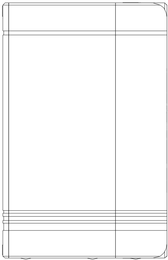
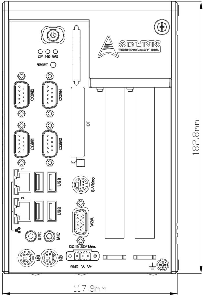
2.1.1 Front View
![CF HD WD\nRESET\nCOM3 COM4\nCOM1 COM2\n1 USB S-Video\n2 USB V3A\nSPK MIG\nDC-IN 32V Max.\nMS KG GND V. W\n182.8mm\n117.8mm](.mxc-2000-50-1z029-2000-002/c6abd5886c82879362e975db009c97abdf273de0a5bfcc56739cf1cb02905e90.jpg)

# 2.1.2 Rear View

![Blank rectangular frame with corner brackets and no text or symbols](.mxc-2000-50-1z029-2000-002/33c21a0701b0beb10f36e2d496a2b73059971bb170bd4116d6f6b42e0d2e9ca8.jpg)

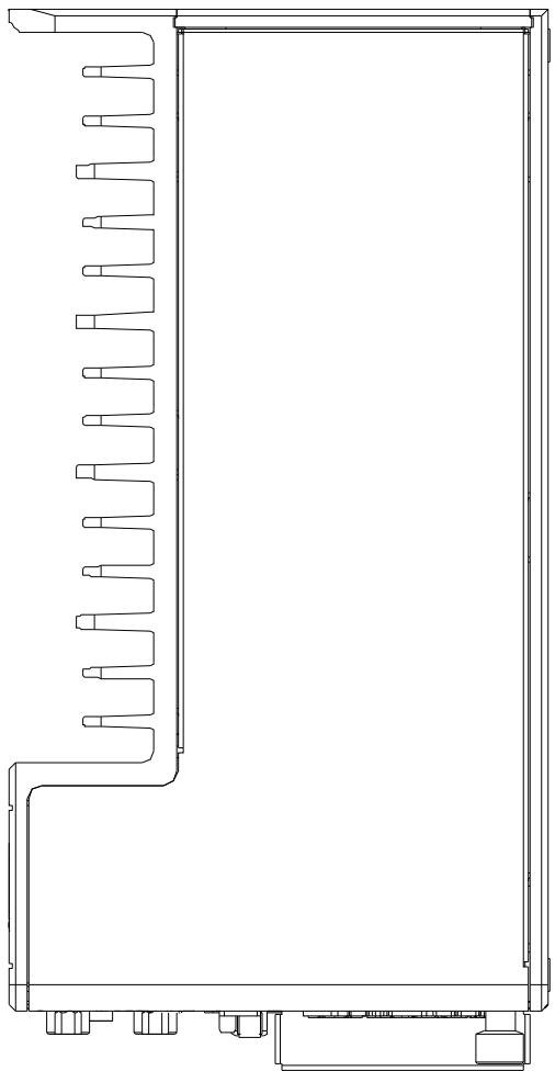
# 2.1.3 Top View

![Technical line drawing of a mechanical component with internal channels and mounting feet (no text or symbols)](.mxc-2000-50-1z029-2000-002/ad936db0dde145f405045bb6fa6733fbf45343f800f701cead3473c3b7b28880.jpg)

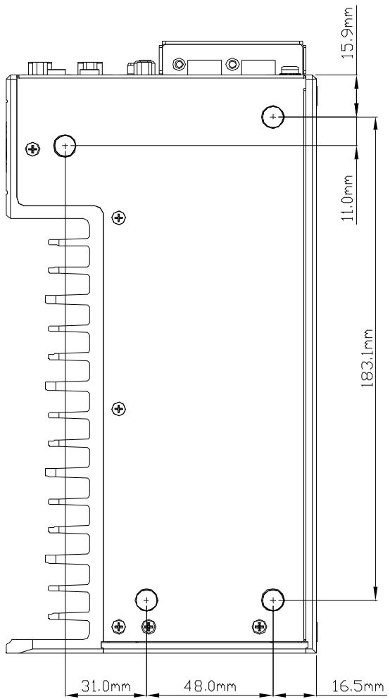
# 2.1.4 Bottom View

![15.9mm\n11.0mm\n183.1mm\n31.0mm 48.0mm 16.5mm](.mxc-2000-50-1z029-2000-002/a3b2dc9be61dffc12427bb3c089afecf02f0c863a6888b6a584bd04de2c43707.jpg)

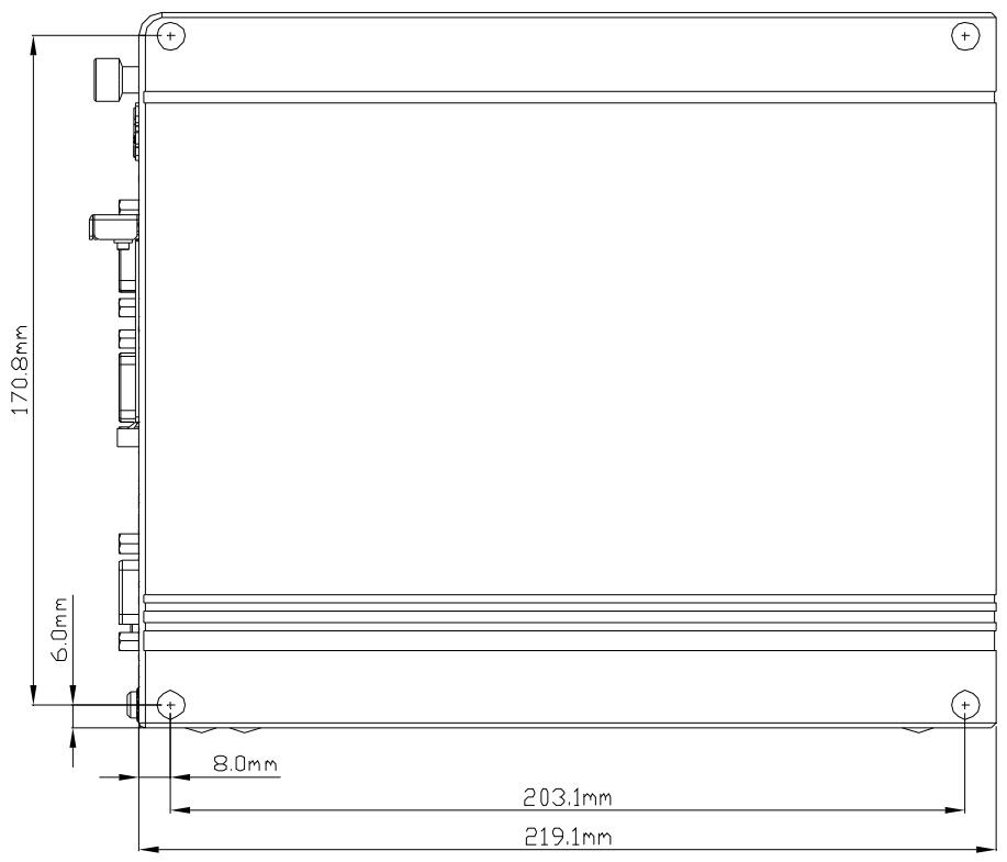
# 2.1.5 Side View (Right)

![170.8mm\n6.0mm\n8.0mm\n203.1mm\n219.1mm](.mxc-2000-50-1z029-2000-002/6ce18280765479ff23de1fce14582f43fa1bb3d2e929e88b137aaa4e88af4075.jpg)

# 2.1.6 Side View (Left)

![Matrix®\nFanless Rugged I/D Platform](.mxc-2000-50-1z029-2000-002/11a4222fb1a070e57b9de098b1ee60da9b0f20a361ffca3606c18ed4fae6afdc.jpg)

# 2.2 Front Panel I/O Connectors

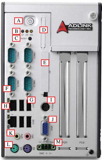
The MXC-2002/2011 controller has the same I/O connector configuration on the front panel, and the MXC-2002D/2011D has an additional 68-pin VHDCI connector for digital input/output. This section describes functions of these I/O connectors.
![ADLINK\nTECHNOLOGY INC.\nA\nB\nC\nD\nE\nF\nG\nH\nI\nJ\nK\nL\nMS\nOS\nADC\nV- V+\nPCI1\nPCI2\nGND V- V+](.mxc-2000-50-1z029-2000-002/0b87a0a9124136fedb2537387810bf138805cccb31dbb978b0eadac3d2a2b0b6.jpg)

<table><tr><td>Symbol</td><td>Function</td><td>Symbol</td><td>Function</td></tr><tr><td>A</td><td>Power button</td><td>H</td><td>Dual Gigabit Ethernet ports</td></tr><tr><td>B</td><td>LED indicators</td><td>I</td><td>S-video connector</td></tr><tr><td>C</td><td>Reset button</td><td>J</td><td>VGA connector</td></tr><tr><td>D</td><td>Digital I/O connector (for MXC-2002D/2011D)</td><td>K</td><td>Audio jacks</td></tr><tr><td>E</td><td>CompactFlash socket</td><td>L</td><td>PS2 keyboard &amp; mouse</td></tr><tr><td>F</td><td>COM ports</td><td>M</td><td>DC power input connector</td></tr><tr><td>G</td><td>USB2.0 ports</td><td></td><td></td></tr></table>

Table 2-1: MXC-2000 Connectors

# 2.2.1 Power Button

The power button is a non-latched push button with a blue LED indicator. The system is turned on when button is pressed, and the power LED is also illuminated. To shut down the system, you can issue shutdown command via the operating system or just press the power button. If the system halts, you can also press the button for 5 seconds to force system shutdown.

# 2.2.2 LED Indicators

There are three LED indicators on the front panel. The following table describes the color and function of the LED indicators.

<table><tr><td>LED indicator</td><td>Color</td><td>Description</td></tr><tr><td>Watchdog (WD)</td><td>Yellow</td><td>Indicates the status of watchdog timer. When the watchdog timer is started, the LED is flashing. And when the timer is expired, the LED is on.</td></tr><tr><td>Hard disk drive (HD)</td><td>Orange</td><td>Indicates the operating state of HDD. When the SATA hard drive or internal CF card is active, the LED indicator is flashing.</td></tr><tr><td>CompactFlash card (CF)</td><td>Green</td><td>Indicates the operating state of CF card on the front panel. The LED indicator is flashing when the CF card is active.</td></tr></table>

Table 2-2: LED Indicators

# 2.2.3 Reset Button

The reset button is used to perform a hard reset of the MXC-2002/2011/2002D/2011D controller. You can use a pin-like object to depress the reset button.

# 2.2.4 Digital I/O Connector (for MXC-2002D and MXC-2011D only)

The MXC-2002D/2011D controller features on-board isolated digital I/O circuit and has a 68-pin VHDCI (Very High Density Cable Interconnect) connector on the front panel. The on-board digital I/O card supports the following features:

▶ 16-CH Isolated DI

▷ Logic high: 5 to 24 V
▷ Logic low: 0 to 1.5 V
▷ Input resistance: 1.2 k @ 0.5 W
▷ Isolation voltage: 2500 V $_{RMS}$
▷ Interrupt source: DI channel 0 and 1

▶ 16-CH Isolated DO

▶ Output Type: Darlington transistor
▷ Sink current up to 100 mA (sustained loading) or 250 mA (peak loading) on each isolated output channel
▷ Supply voltage: 5 to 35 V $_{DC}$
▷ Isolation voltage: 2500 V $_{RMS}$
▷ Data transfers: programmed I/O

![| Position | Position Label | Position Description |\n|---|---|---|\n| (1) VDD | (24) IDI_1L | (47) EOGND |\n| (2) EOGND | (25) IDI_0H | (48) IDO_10 |\n| (3) IDO_7 | (26) IDI_0L | (49) EOGND |\n| (4) EOGND | (27) IDI_11 | (50) IDO_9 |\n| (5) IDO_6 | (28) IGND | (51) EOGND |\n| (6) EOGND | (29) IDI_10 | (52) IDO_8 |\n| (7) IDO_5 | (30) IGND | (53) IDI_7H |\n| (8) EOGND | (31) IDI_9 | (54) IDI_7L |\n| (9) IDO_4 | (32) IGND | (55) IDI_6H |\n| (10) EOGND | (33) IDI_8 | (56) IDI_6L |\n| (11) IDO_3 | (34) IGND | (57) IDI_5H |\n| (12) EOGND | (35) VDD | (58) IDI_5L |\n| (13) IDO_2 | (36) ISO5V | (59) IDI_4H |\n| (14) EOGND | (37) EOGND | (60) IDI_4L |\n| (15) IDO_1 | (38) IDO_15 | (61) IDI_15 |\n| (16) EOGND | (39) EOGND | (62) IGND |\n| (17) IDO_0 | (40) IDO_14 | (63) IDI_14 |\n| (18) EOGND | (41) EOGND | (64) IGND |\n| (19) IDI_3H | (42) IDO_13 | (65) IDI_13 |\n| (20) IDI_3L | (43) EOGND | (66) IGND |\n| (21) IDI_2H | (44) IDO_12 | (67) IDI_12 |\n| (22) IDI_2L | (45) EOGND | (68) IGND |\n| (23) IDI_1H | (46) IDO_11 | |\nThe image contains two rows of amino acid sequences and one column of the same sequence. The numbers below each row correspond to the position of the sequence in parentheses. The labels above the sequences are explicitly written on the left side.](.mxc-2000-50-1z029-2000-002/e960490c238e8d7c4bef254ffae6f19c58f56563ac59f0b5665d40753b95449f.jpg)

Table 2-3: Digital I/O Connector

# Legend:

▶ IDI\_n: Isolated digital input channel #n.
▶ IDO\_n: Isolated digital output channel #n.
▶ IDI\_nH: High input of isolated differential DI channel #n.
▶ IDI\_nL: Low input of isolated differential DI channel #n.
▶ EOGND: Ground return path of isolated output channels.
▶ VDD: Power input signal for fly-wheel diode of DO channels.

# 2.2.5 CompactFlash Socket

The MXC-2002/2011/2002D/2011D controller is equipped with a Type I CompactFlash socket which is located on the front panel. The CF interface is transferred from USB by an ASIC. Due to the nature of USB interface, the CF card is hot-pluggable, but cannot be a boot device with a OS installed. You can install your operating system to the internal CF card, which is described in section 2.3.1.

# 2.2.6 COM Ports

The MXC-2002/2011/2002D/2011D controller provides four COM ports in the form of D-Sub 9P connectors. COM1 and COM2 ports support RS-232/RS-422/RS-485 by jumper selection, while COM3 and COM4 ports support RS-232 function only. Please refer to section 3.3 for the instructions of setting RS-232/422/485 jumpers of COM1 and COM2 ports.

![COM3\nCOM4\n5\n9\nCOM1\nCOM2\n1\n6\nCF](.mxc-2000-50-1z029-2000-002/6f2d86b728bff59922ae1275947c8f957847ea06da0dccd237bada6a85f7375f.jpg)

<table><tr><td rowspan="2">PIN</td><td colspan="3">Signal Name</td></tr><tr><td>RS-232</td><td>RS-422</td><td>RS-485</td></tr><tr><td>1</td><td>DCD#</td><td>TXD422-</td><td>485DATA-</td></tr><tr><td>2</td><td>RXD#</td><td>TXD422+</td><td>485DATA+</td></tr><tr><td>3</td><td>TXD#</td><td>RXD422+</td><td></td></tr><tr><td>4</td><td>DTR#</td><td>RXD422-</td><td></td></tr><tr><td>5</td><td>GND</td><td></td><td></td></tr><tr><td>6</td><td>DSR#</td><td></td><td></td></tr><tr><td>7</td><td>RTS#</td><td></td><td></td></tr><tr><td>8</td><td>CTS#</td><td></td><td></td></tr><tr><td>9</td><td>RI#</td><td></td><td></td></tr></table>

# 2.2.7 USB 2.0 connectors

The MXC-2002/2011/2002D/2011D controller provides four USB 2.0 ports in Type A USB connectors on the front panel. All USB ports are compatible with high-speed, full-speed and low-speed USB devices. The MXC-2000 series supports multiple boot devices, including USB flash drive, USB external hard drive, USB floppy, USB CD-ROM and etc. The boot priority and boot device can be configured in BIOS. Please refer to section 4.1.5 for details.

# 2.2.8 Gigabit Ethernet (RTL8111C)

The MXC-2002/2011/2002D/2011D controller has two GbE ports on the front panel by Realtek 8111C Gigabit Ethernet controller. The Ethernet controller supports the following features:

▶ x1 PCI Express® interface with 2.5 GHz signaling
▶ Advanced error reporting
▶ Message signaled interrupts
▶ TCP segmentation offload/large-send support
▶ 802.3x flow control-compliant
▶ IEEE 802.1p and 802.1q support
▶ 10/100/1000 IEEE 802.3-compliant
▶ Automatic MDI/MDIX crossover at all speeds
▶ ACPI 2.0 specification
▶ Wake-On-Link feature
▶ Fully integrated ASF 2.0 functionality with on-chip $\mu$ c
▶ SMBus 2.0 master interface for ASF functionality
▶ Serial Peripheral Interface (SPI) for ASF firmware

![Close-up of a black electronic device with two small components and three connected square boxes below (no visible text or symbols)](.mxc-2000-50-1z029-2000-002/4c50d9214aaab7376221a6a54681877532e302cc69d587dc450f7324b444c99a.jpg)

Active/Link LED
Yellow
Speed LED
Green/Orange

# Active/Link LED

<table><tr><td>LED Color</td><td>Status</td><td>Description</td></tr><tr><td rowspan="3">Yellow</td><td>Off</td><td>Ethernet port is disconnected</td></tr><tr><td>ON</td><td>Ethernet port is connected and no data transmission</td></tr><tr><td>Flashing</td><td>Ethernet port is connected and is transmitting/receiving data.</td></tr></table>

Table 2-4: Active/Link LED

# Speed LED

<table><tr><td>LED Color</td><td>Status</td><td>Description</td></tr><tr><td rowspan="3">Green/Orange</td><td>Green</td><td>10 Mbps</td></tr><tr><td>Green</td><td>100 Mbps</td></tr><tr><td>Orange</td><td>1000 Mbps</td></tr></table>

Table 2-5: Speed LED

# 2.2.9 S-Video Connector

The MXC-2002/2011/2002D/2011D controller provides 7-pin S-video connector on the front panel. The S-Video signals are available on the four matching pins (pin #1 to #4). And one of the other three pins carries the Composite Video signal for non-S-Video displays. A specific "S-Video to Composite" cable is shipped with the MXC-2000 series for connecting to the composite video connector of your TV.

![Close-up of a circular mechanical component with multiple pins (no visible text or symbols)](.mxc-2000-50-1z029-2000-002/1eafeaadd6721c00f93428c4bd65d0dd6f79f3e8756583ce9ff2a5a171129204.jpg)

![4\n7\n3\n2\n6\n5\n1](.mxc-2000-50-1z029-2000-002/7f1456894a19055508c55c66e26a7f4e6abcc56cccc3af09710a5f1b13e5002e.jpg)

<table><tr><td>PIN</td><td>Signal Name</td></tr><tr><td>1</td><td>Ground (all grounds are connected together)</td></tr><tr><td>2</td><td>Ground</td></tr><tr><td>3</td><td>S-Video Luminance Signal</td></tr><tr><td>4</td><td>S-Video Chrominance Signal</td></tr><tr><td>5</td><td>Composite Video signal</td></tr><tr><td>6</td><td>Ground</td></tr><tr><td>7</td><td>--</td></tr></table>

Table 2-6: S-Video Connector

# 2.2.10 VGA connector

The D-sub 15-pin VGA connector is used to connect your MXC-2002/2011/2002D/2011D controller to a monitor. The MXC-2000 series supports only analog (VGA) monitors.

# 2.2.11 Audio Jacks

The MXC-2002/2011/2002D/2011D controller implements Intel High Definition audio using Realtek ALC262 chip. The HD audio supports up to 24-bit, 192 Kbps high quality headphone/speaker output and microphone input. Users can access the audio jacks on the front panel of MXC-2000 series. The pink jack is for microphone input, and the green jack is for speaker output.

# 2.2.12 Keyboard & Mouse PS2 connectors

The MXC-2002/2011/2002D/2011D controller provides connectors for connecting PS2 keyboard and mouse. The green connector is for PS/2 mouse and the purple one is for PS/2 key-board.

# 2.2.13 DC Power Input Connector

The DC power input connector of the MXC-2002/2011/2002D/2011D controller consists of three pins: V+, V- and chassis ground from right to left respectively. V+ and V- pins are for DC power input and chassis ground pin allows you connect the chassis to ground for better EMC compatibility. The DC power input of MXC-2000 series allows a voltage input from 9 VDC to 32 VDC. The MXC-2000 series also features the under/over voltage input protection. System will automatically shut off when input voltage is too low (under 7.5 V) or too high (over 34 V).

# 2.3 Internal I/O Connectors

The section describes the internal I/O connectors of the MXC-2000 series. MXC-2002, MXC-2011, MXC-2002D and MXC-2011D have the same internal I/O connectors. The figure showed below is what's inside the MXC-2000 series.

![A\nB\nC\nD](.mxc-2000-50-1z029-2000-002/99b111af684bca2474aa3b356743dc83df2d7d1c01548c3bc228d435f4a3b90c.jpg)

<table><tr><td>Symbol</td><td>Function</td></tr><tr><td>A</td><td>CompactFlash Socket</td></tr><tr><td>B</td><td>COM ports setting jumpers</td></tr><tr><td>C</td><td>SATA connector</td></tr><tr><td>D</td><td>Clear CMOS button</td></tr></table>

# 2.3.1 CompactFlash Socket

The internal CompactFlash socket is connected to chipset via IDE interface, and can be used as an alternative storage device for system installation. You can boot up the MXC-2002/2011/2002D/2011D controller via a CF card with OS installed. Due to the nature of IDE interface, the CF card is not hot-pluggable and must be installed before system power on. Please refer to section 3.4 for the illustration of installing a CF card.

# 2.3.2 COM Ports Setting Jumpers

These six jumpers (JP2/JP3/JP4/JP5/JP6/JP7) are used for configuring COM1 and COM2 ports to RS-232/422/485 mode. Please refer to section 3.3 for the illustration of setting COM1 and COM2 ports.

# 2.3.3 SATA Connector

The MXC-2002/2011/2002D/2011D controller provides a SATA Gen.1 port. The SATA host controller supports two modes of operation, the legacy mode using I/O space and AHCI mode using memory space. This SATA connector is designed for installing a 2.5" hard disk drive or solid state disk (SSD). The HDD or SSD must be installed into SATA connector with a specific bracket mounted on the chassis. Please refer to section 3.1 for the illustration of installing a 2.5" hard disk drive or SSD.

# 2.3.4 Clear CMOS Button

When encountering the abnormal condition that causes the MXC-2002/2011/2002D/2011D controller failed to boot, you can try to clear the BIOS content stored in CMOS and restore to the default setting. To clear CMOS, just press the button and hold on for 1\~2 second then release it. After doing that, the CMOS will restore to the factory default setting.

# 3 Getting Started

This chapter demonstrates how to install the hard drive, PCI/PCIe card and CompactFlash card into system. Additional COM ports jumper settings and MXC-2000 series wall-mount installation are also discussed.

# 3.1 Installing a hard disk drive

Before installing a hard disk drive, you should remove the top cover of chassis first. Please follow the instruction below.

1. Unscrew the screw on the front panel by hand or a screwdriver.

![Front view of a network equipment unit with visible ports, connectors, and a logo (no readable text or symbols beyond branding)](.mxc-2000-50-1z029-2000-002/037ec23494387126d3103857859cd127346c057ea287a3c2b91c7fa8154dc799.jpg)

2. Hold the screw and pull it toward to your body side.

![Pull](.mxc-2000-50-1z029-2000-002/91ae152197c54d4b994212eeb5793bc41220e79585f2d66f0edf0fb45e9510fe.jpg)

3. Then you can remove the top cover by pulling it up.

![Close-up of hands installing a metallic electronic device into a case, with a red arrow indicating the component's direction (no text or symbols visible)](.mxc-2000-50-1z029-2000-002/37151cae9bed721fb80b6dc685d945f31be308ac37cc3be106f05d432922ddf7.jpg)

4. After removing the top cover, please use a screwdriver to unscrew two screws on the top side.

![Interior view of a computer case with a hand using a screwdriver to adjust the internal circuit board (no text or symbols visible)](.mxc-2000-50-1z029-2000-002/27112133d27f59bcd2f4eda7f7824bca61b65e03165f944d0d79e9a0e26dc2d1.jpg)

5. Place the chassis upside down and unscrew another two screws on the bottom side.

![Hand using a green screwdriver to adjust or install a device into a black electronic device casing (no text or symbols visible)](.mxc-2000-50-1z029-2000-002/50f3168675c925f5a5e109808e56c8f06f7033b27d8194f47bbab75a9577ca5c.jpg)

6. Pull up the HDD bracket.

![Interior view of a computer tower case showing internal components and a hand inserting a component (no text or symbols visible)](.mxc-2000-50-1z029-2000-002/2a4af0e08059559c342e4369e42feee9145b3bbeb2bf79e3cc9c6fea8bf34960.jpg)

7. A 2.5" HDD or SSD should be mounted to the specific HDD bracket before you install it into the MXC-2002/2011/2002D/2011D controller. You can find four M3 screws in the screw pack. Fasten four screws to attach your HDD or SSD to the bracket.

![Close-up of a metallic hard disk drive with a screwdriver inserted, showing internal components and mounting holes (no readable text or symbols)](.mxc-2000-50-1z029-2000-002/2573b297761c16d924f9399384649df364ff5facb6f2e8224d985d0eba42f7d8.jpg)

8. Install the 2.5" HDD or SSD by gently push the HDD/SSD bracket down to the SATA connector on the PCB.

![Interior view of a computer case with visible circuit board and internal components, no text or symbols present.](.mxc-2000-50-1z029-2000-002/65934ee539ebbeb6baa44d3ad89d18214dce996ff343723fd4f2c484f292bd1c.jpg)

9. Fasten four screws on the top side and bottom side. And then put the top cover of chassis back.

![Two views of a computer case showing a hand using a screwdriver to adjust the internal components (no text or symbols visible)](.mxc-2000-50-1z029-2000-002/fa615096f720271cdeb8deddbc0a3c7568350f030169b455021ffa6aef0970cf.jpg)

# 3.2 Installing PCI/PCIe card

Before installing a PCI/PCIe card, you should remove the top cover of chassis first. Please follow steps 1-3 in section 3.1 to remove the top cover, and follow the following steps to install your PCI/PCIe card.

1. Insert your PCI or PCIe card to the PCI/PCIe slot. Note that there is a joint point on the lower side. Please make sure that the lower edge of your PCI/PCIe card is placed into the joint point.

![Photo of a computer case with visible ports, connectors, and a hand inserting a component into the case.](.mxc-2000-50-1z029-2000-002/c057e68a66ce02711d6b713f932dd3cdb047b5c71538faa019b602b3a55f5eee.jpg)

2. After installing your PCI/PCIe card, you can use the hold-on bars shipped with MXC-2000 series to hold your card. You can find the hold-on bars in the accessory box.

![Close-up of hands installing or adjusting a computer motherboard with visible circuitry and components (no text or symbols)](.mxc-2000-50-1z029-2000-002/416791c73e71ba91d0dd2104de97b79b3605419f64f5fa965e6e3fe705194cba.jpg)

3. Adjust the position of hold-on bar to make it hold you card firmly. And tighten the screw to fix the hold-on bar.

![Close-up of hands installing a screwdriver into an open electronic device (no visible text or symbols)](.mxc-2000-50-1z029-2000-002/a12a984c54367c36e1a2bc9f9536c37f203542eb51cfb47dc1ab815a8b268169.jpg)

4. Replace the top cover.

# 3.3 Jumper Setting for COM1 and COM2

COM1 and COM2 of the MXC-2002/2011/2002D/2011D controller supports RS-232, RS-422 and RS-485. JP2, JP3, JP4, JP5, JP6 and JP7 are used to set the operation mode of COM1 and COM2. Please refer to the following table for the jumper settings.

![| RS | COM1 | COM2 |\n|---|---|---|\n| RS232 | JP3 6 5 | JP2 6 5 JP4 6 5 4 3 |\n| RS422 | JP3 2 1 | JP2 2 1 JP4 6 5 2 1 |\n| RS485 | JP3 2 1 | JP2 2 1 JP4 4 3 2 1 |\n| | JP6 6 5 | JP5 6 5 JP7 4 3 |](.mxc-2000-50-1z029-2000-002/14b3080f5cc9147a9ad41932877159f79a8f78464f7cd4b073a13677d9bb0bbf.jpg)

# 3.4 Installing a CF Card

The MXC-2002/2011/2002D/2011D controller provides an internal CompactFlash socket to accommodate a CF card as a replacement of hard disk drive. You can also install a SATA hard disk drive and CF card simultaneously and set the boot device preferences in BIOS. Please follow the instructions below to install the CF card.

1. Follow steps 1-3 in section 3.1 to remove the top cover of the chassis.
2. Align your CF card with the guide of CF socket.

![Interior view of a computer tower case showing internal components like CPU, BOS, and motherboard (no visible text or labels)](.mxc-2000-50-1z029-2000-002/51340a802662bb5ff97cc0c304282073ea72d1de904c66871384ffeb828cf565.jpg)

3. Gently push your CF card down to make it firmly attached to the internal CF socket.

![Interior view of a computer chassis showing internal components like CPU, RAM, and motherboard (no visible text or labels)](.mxc-2000-50-1z029-2000-002/359df1bafc77d6493d7b744ae24b361d1476761f2ba585b0645e9ffaac65b199.jpg)

4. Replace the top cover.

# 3.5 Plug-in DC power

Note: Before plugging DC power into the MXC-2002/2011/2002D/2011D controller, please make sure you have correct voltage and polarity for your DC input. An improper input voltage or polarity will cause system damage.

The DC power input connector of the MXC-2002/2011 controller consists of three pins, V+, V-, and chassis ground from right to left respectively. The DC power input accepts an input voltage from 9 VDC to 32 VDC. User should connect the DC power as the figure showed below. Two screws of the plug should be fastened to prevent the plug loosing.

![USB\nVGA\nSPK\nMIC\nV-\nV+\nDC-IN 32V Max\nMS\nKB](.mxc-2000-50-1z029-2000-002/000ce1b355177e5d9700251cdbd6a3f394118442be59fe0eeb60a6efe8a7f682.jpg)

# 3.6 Mounting MXC2000 Series Controller

The MXC-2002/2011/2002D/2011D controller is shipped with wall-mount brackets. You can use the wall-mount brackets and accessory screws to mount the MXC-2002/2011/2002D/2011D controller on the wall.

The procedures of mounting MXC-1000 series are illustrated step by step below:

1. Remove four plastic pads in the four corners.

![3D rendering of a black rectangular electronic component with mounting holes and red circular annotations (no text or symbols)](.mxc-2000-50-1z029-2000-002/73d89004de6ee65856c48f70adba4e6f738186c192be53f3ac4a7146fa4d13e7.jpg)

2. You can find two wall-mount brackets and four M4 screws in the accessory box shipped with the controller. Fasten four screws to fix the brackets to the chassis.

![3D CAD model of a mechanical housing component with mounting brackets and a close-up inset showing internal detail (no text or symbols)](.mxc-2000-50-1z029-2000-002/61afcb624746f0cea3f3669cd87442ffb58e58d5ea194a69d0e1600a04c8c249.jpg)

3. You should have the final assembly showed below. Then you can mount the MXC-2002/2011/2002D/2011D controller on the wall via proper screw holes.

![Matrix®\nFaner Rugged TO Platform](.mxc-2000-50-1z029-2000-002/90db13aa0d35bf8abd0c66ce8ee1c79d8074a0f18de164218996948a9e708917.jpg)

# 3.7 Cooling Considerations

The hot components of MXC-2002/2011/2002D/2011D controller (such as CPU, north bridge and south bridge) are all placed on the left side of system. These components are directly contacted to the aluminum heat sink via thermal pads. Heat generated by components is majorly dissipated though heat sink. To have better efficiency of heat dissipation, please keep a minimal 2 inches (5 cm) clearance off the heat sink side of the MXC-2002/2011/2002D/2011D controller.

![3D technical diagram of an internal computer module with green circuit board and labeled components (no readable text or symbols)](.mxc-2000-50-1z029-2000-002/a0c7bbc8cb2bdf6ca446c6064402c7d0512b20a80d7b74e7be0dc6569bd73241.jpg)

# 4 BIOS Settings and Driver Installation

# 4.1 BIOS Setting

The Basic Input/Output System (BIOS) is a program that provides a basic level of communication between the processor and peripherals. In addition, the BIOS also contains codes for various advanced features applied to the MXC-2002/2011/2002D/2011D controller. The BIOS setup program includes menus for configuring settings and enabling features of MXC-2000 series. Most users do not need to use the BIOS setup program, as the MXC-2002/2011/2002D/2011D controller ships with default settings that work well for most configurations.

In this section, BIOS options are illustrated.

Warning: Changing BIOS settings may lead to incorrect controller behavior and possibly an unbootable controller. If this happens, follow the instructions in Section 2.4.4 to clear CMOS and then restore the default settings. In general, do not change a BIOS setting unless you are absolutely certain of what it does.

# 4.1.1 Main

# 4.1.1.1 System Time/System Date

Use this option to specify the system time and date. Highlight System Time or System Date using the up or down &lt;Arrow&gt; keys. Enter new values using the keyboard then press &lt;Enter&gt; key. Press the &lt;Tab&gt; key to move between fields. The date must be entered in MM/DD/YY format. The time is entered in HH:MM:SS format.

Note: The time is in 24-hour format. For example, 5:30 A.M. appears as 05:30:00, and 5:30 P.M. as 17:30:00.

# 4.1.2 Advanced

# 4.1.2.1 CPU Configuration

# Hyper Threading Technology

This option allows you to Enable/Disable Hyper-Threading Technology.

# Intel® SpeedStep Tech

This option enables or disables Intel SpeedStep technology.

# 4.1.2.2 IDE Configuration

# ATA/IDE Configuration

This option specifies whether the IDE channels should be initialized in Compatible Mode or Enhanced Mode. The settings are Disabled, Compatible and Enhanced. The default option is Compatible.

# Legacy IDE Channels

When running in compatible mode, the SATA channel can be configured as a legacy IDE channel. The location of the IDE channel is selectable.

# Primary IDE Master

Press &lt; Enter &gt; to configure the first device (master) on IDE interface.

# Primary IDE Slave

Press &lt; Enter &gt; to configure the second device (slave) on IDE interface.

# Secondary IDE Master

Press &lt; Enter &gt; to configure the first device (master) on secondary IDE interface.

# Secondary IDE Slave

Press &lt; Enter &gt; to configure the second device (slave) on secondary IDE interface.

# Hard Disk Write Protect

Set this option as Enabled to prevent the hard disk drive from being overwritten.

# IDE Detect Time Out

This option allows you to stop searching for IDE devices within the specified number of seconds.

# ATA(PI) 80Pin Cable Detection

Selects the mechanism for detecting the type of IDE cable used.

# 4.1.2.3 SuperIO Configuration

# Serial Port1/ Port2/ Port3/ Port4 Address

These four options specify the base I/O port address of serial port1 to serial port4.

Note: Do not set the same value for different serial ports to avoid resource conflict.

# 4.1.2.4 Hardware Health Configuration

The hardware health option allows users to monitor hardware status including CPU temperature, system temperature, and system voltages (Vcore, +5V, +3.3V, +12V, +1.8V, 5VSB, VBAT).

# 4.1.2.5 Remote Access Configuration

This option allows a remote access by another computer to get POST messages and send commands through serial port access.

# Remote Access

Select this option to Enable or Disable the BIOS remote access feature.

Note: Enabled Remote Access requires a dedicated serial port connection. Once the corresponding serial port is disabled in SuperIO Configuration, you shall not use it for remote access to avoid abnormal operation.

# Serial Port Number

Specify the serial port you want to use for remote access. Available options are COM1, COM2, COM3 and COM4.

Note: If you change the serial port settings in Advanced $\Rightarrow$ SuperIO Configuration, you need to Save Changes and Exit, and then reboot the system so that the changes will be reflected in the Remote Access options.

# Serial Port Mode

Specify the baud rate of the serial port for console redirection. Available options are 115200 8,n,1; 57600 8,n,1; 19200 8,n,1; and 9600 8,n,1.

# Flow Control

Specify Flow Control mode for console redirection. Available options are None, Hardware, and Software.

# Redirection after BIOS POST

This option allows you to set Redirection configuration after BIOS POST. Available options are Disabled, Boot Loader, and Always.

<table><tr><td>Option</td><td>Description</td></tr><tr><td>Disabled</td><td>Turn off the redirection after POST.</td></tr><tr><td>Boot Loader</td><td>Activate the redirection during POST and Boot Loader.</td></tr><tr><td>Always</td><td>Always activate the redirection.</td></tr></table>

Table 4-1: Redirection after BIOS POST

# Terminal Type

This option is used to specify either VT100/VT-UTF8 or ANSI terminal type. Available value is ANSI, VT100, or VT-UTF8.

# VT-UTF8 Combo Key Support

This option enables VT-UTF8 Combination Key Support for ANSI/VT100 terminals. Available options are Enabled and Disabled.

# Sredir Memory Display Delay

This option specifies the delay in seconds to display memory information. Available options are Delay, Delay 1 Sec, Delay 2 Sec, and Delay 4 Sec.

# 4.1.2.6 ACPI Configuration

# Suspend Mode

This setting specifies either S1 (POS) or S3 (STR) system suspend mode. The Optimal and Fail-Safe Default setting is S3 (STR).

<table><tr><td>Option</td><td>Description</td></tr><tr><td>S1 (POS)</td><td>Power On Suspend - Maintain current system status, such as power supply and memory context, except for CPU is not executing instructions. Devices that can wake-up the system can cause CPU to continue execute from where it left off.</td></tr></table>

Table 4-2: Suspend Mode

<table><tr><td>Option</td><td>Description</td></tr><tr><td>S3 (STR)</td><td>Suspend to RAM - System enters a low power state instead of completely shut-off. Standby power and power supply for memory are maintained.</td></tr><tr><td>Auto</td><td>Depends on OS, OS automatically selects suspend mode it supports.</td></tr></table>

Table 4-2: Suspend Mode

# Power Button Mode

Specify the behavior when pressing power button in DOS environment.

<table><tr><td>Option</td><td>Description</td></tr><tr><td>On/Off</td><td>Turn off system directly when pressing power button.</td></tr><tr><td>Suspend</td><td>Turn system to suspend mode when pressing power button.</td></tr></table>

Table 4-3: Power Button Mode

# Resume On LAN RTL8111C

This option specifies to enable or disable RTL8111C LAN wake-up function. If you enable the LAN wake-up function, you can send a “magic packet” via Ethernet from a remote computer to turn on the MXC-2002/2011/2002D/2011D controller.

# Resume On RTC Alarm

This option selects to enable or disable RTC (Real Time Clock) wake-up function. RTC wake-up function allows you to turn on the MXC-2002/2011/2002D/2011D controller at specific date/time automatically.

# 4.1.2.7 USB Configuration

# Legacy USB Support

Legacy USB Support also refers to USB mouse and keyboard support. Normally if this option is not enabled, attached USB mouse or keyboard will not be available until a USB compatible operating system fully boots up with USB drivers loaded. With this option enabled, attached USB mouse or keyboard is usable even when no USB drivers loaded.

<table><tr><td>Option</td><td>Description</td></tr><tr><td>Disabled</td><td>Set this value to prevent the use of any USB device during system boot or in DOS environment.</td></tr><tr><td>Enabled</td><td>Set this value to allow the use of USB devices during system boot or in DOS environment.</td></tr><tr><td>Auto</td><td>This option automatically detects USB keyboard or mouse and if found, allows the usage during system boot or in DOS environment.</td></tr></table>

Table 4-4: Legacy USB Support

# USB 2.0 Controller Mode

The USB 2.0 Controller Mode configures the data rate of the USB port. Available options are FullSpeed (12 Mbps) and HiSpeed (480 Mbps).

# BIOS EHCI hand-off

This option provides a workaround for OSes without ECHI hand-off support. The change of EHCl ownership should be claimed by the EHCl driver.

# 4.1.2.8 PCI Express Configuration

# PCIE Port (0-5)

This option allows you to enable or disable corresponding PCIe port.

# PCIE High Priority Port

This option allows you to set a high priority PCIe port. Transactions on this port have higher priority than other ports.

# PCIE Port (0-5) IOxAPIC Enable

This option allows you to control the availability of the PCIE Port 0-5 IOxAPIC.

# 4.1.2.9 PCIPnp

# PCI Latency Timer

Specify this value to allow the PCI Latency Timer to be adjusted. This option sets the latency of all PCI devices on the PCI bus.

# Allocate IRQ to PCI VGA

If this option is set to Yes, the BIOS assigns an IRQ for a PCI VGA card.

# PCI IDE BusMaster

If this option is set to Enabled, the BIOS uses PCI bus mastering for reading/writing IDE drives.

# IRQ

Specify this value to modify the IRQ settings.

<table><tr><td>Option</td><td>Description</td></tr><tr><td>Available</td><td>Allow the specified IRQ to be used by a PCI/PnP device..</td></tr><tr><td>Reserved</td><td>Allow the specified IRQ to be used by a legacy ISA device.</td></tr></table>

Table 4-5: PCIPnp IRQ Settings

# 4.1.3 Chipset

# 4.1.3.1 North Bridge Configuration

# DRAM Frequency

Specify DRAM frequency. You can specify whether let BIOS set DRAM frequency automatically or configure it manually (400 MHz or 533 MHz).

# Configure DRAM Timing by SPD

Specify Enable to allow the timing setting of DRAM to be configured from SPD or Disable to configure it manually.

# Boots Graphic Adapter Priority

Specify which graphics controller to use as the primary boot display device. Please note that MXC-2000 series only supports Intel integrated graphic device (IGD). You should always set this option as IGD to ensure normal operation.

# Internal Graphics Mode Select

Specify the size of system memory used by internal graphics device. 8MB is recommended.

# DVMT Mode Select

Dynamic Video Management Technology (DVMT) allows additional system memory to be dynamically allocated in operating system for graphics usage. Once the application is closed, the allocated memory is released and is then available for system usage. DVMT ensures a solid balance between system performance and graphics performance.

<table><tr><td>Option</td><td>Description</td></tr><tr><td>Fixed Mode</td><td>The graphics driver reserves a fixed portion of the system memory as graphics memory.</td></tr><tr><td>DVMT Mode</td><td>The graphics driver dynamically allocates system memory for graphics usage, according to system and application demands.</td></tr><tr><td>Combo Mode</td><td>The graphics driver reserves a fixed amount of memory as dedicated graphics memory, as well as dynamically allocates system memory in operating system according to system and application demands.</td></tr></table>

Table 4-6: DVMT Mode Select

# Boots Display Device

Specify the display device output when system boots up or in DOS environment. You can either specify VGA output or TV output.

# TV Standard

For S-video or composite .video output, you can specify TV standard to match the TV signal input in different regions. The available options are NTSC, PAL and VBIOS-Default.

# 4.1.3.2 South Bridge Configuration

# USB Function

Specify the number of USB ports enabled in Matrix controller. The default value is 8 USB ports.

# USB 2.0 Controller

Specify whether to enable or disable built-in USB 2.0 controller in south bridge chip.

# Audio Controller

Enable/Disable the Azalia HD audio or AC97 audio.

# Restore on Power Loss

Determine the system status when external power is restored after a power loss.

<table><tr><td>Option</td><td>Description</td></tr><tr><td>Power Off</td><td>The Matrix controller remains off when external DC power is supplied.</td></tr><tr><td>Power On</td><td>The Matrix controller is turn on when external DC power is supplied. You can specify this option to mimic the AT power behavior, and use an external switch to control the on/off of Matrix controller.</td></tr><tr><td>Last State</td><td>If encountering a power loss, the Matrix controller resumes to the previous on/off state when external power is normally supplied.</td></tr></table>

Table 4-7: Restore on Power Loss

# 4.1.4 Security

The Security setup menu provides both a Supervisor and a User password. If you use both passwords, the Supervisor password must be set first.

To uninstall the passwords, you can simply set a NULL password.

# Change Supervisor Password

Select Change Supervisor Password and press &lt; Enter &gt;. And enter your password in the appearing message box as prompted. The password is stored in NVRAM after setup completes.

# User Access Level

This option appears after specifying Supervisor password, and allows you to specify the access level for users.

<table><tr><td>Option</td><td>Description</td></tr><tr><td>No Access</td><td>Users are not allowed to access the BIOS setting.</td></tr><tr><td>View Only</td><td>Users are allowed to view BIOS setting but not allowed to change it.</td></tr><tr><td>Limited</td><td>Users are allowed only to change limited items in BIOS.</td></tr><tr><td>Full Access</td><td>Users are allowed to access and change all setting items in BIOS.</td></tr></table>

Table 4-8: User Access Level

# Change User Password

Select Change User Password and press &lt; Enter &gt;. And enter your password in the appearing message box as prompted. The password is stored in NVRAM after setup completes.

# Password Check

This option appears after specifying Supervisor password.

<table><tr><td>Option</td><td>Description</td></tr><tr><td>Setup</td><td>Check password when entering BIOS setup.</td></tr><tr><td>Always</td><td>Check password when system booting.</td></tr></table>

# 4.1.5 Boot

# 4.1.5.1 Boot Settings Configuration

Quick Boot

<table><tr><td>Option</td><td>Description</td></tr><tr><td>Disabled</td><td>Specify BIOS to perform all POST tests.</td></tr><tr><td>Enabled</td><td>Specify BIOS to skip certain POST test to boot faster.</td></tr></table>

Quiet Boot

<table><tr><td>Option</td><td>Description</td></tr><tr><td>Disabled</td><td>Specify BIOS to display POST messages.</td></tr><tr><td>Enabled</td><td>Specify BIOS to display the OEM logo.</td></tr></table>

# Bootup Num-Lock

Specify whether the Number Lock is on or off after power-on.

# Wait for 'F1' If Error

If this option is specified as Disabled, BIOS does not wait for users to press the &lt;F1&gt; key if any error occurs.

# Hit 'DEL' Message Display

If this option is specified as Enabled, the system displays the message "Press DEL to run Setup during POST"

# RTL8111C PXE ROM

Disable/Enable the RTL8111C PXE function.

# 4.1.5.2 Boot Device Priority

Specify the priority of boot devices. All installed boot devices are detected during POST and displayed on the screen. You can refer to the following steps to specify different boot device.

# Boot from a SATA hard drive

1. Select Hard Disk Drives and press Enter.
2. Your SATA hard drive is displayed with its identification string. Specify it as 1st Drive.
3. Go back to upper level and select your SATA hard drive in 1st Boot Device.

# Boot from CF card

1. Select Hard Disk Drives and press Enter.
2. Your CF card is displayed with its identification string. Specify it as 1st Drive.
3. Go back to upper level and select your CF card in 1st Boot Device.

# Boot from USB CD/DVD drive

1. Select USB Drives and press Enter.
2. Your CD/DVD drive is displayed with its identification string. Specify it as 1st Drive.
3. Go back to upper level and select your CD/DVD drive in 1st Boot Device.

# Boot from USB Flash disk

1. Select USB Drives and press Enter.
2. Your USB flash disk is displayed with its identification string. Specify it as 1st Drive.
3. Go back to upper level and select your USB flash disk in 1st Boot Device.

# Boot from USB external hard drive

1. Select USB Drives and press Enter.
2. Your USB external hard drive is displayed with its identification string. Specify it as 1st Drive.
3. Go back to upper level and select your USB external hard drive in 1st Boot Device.

# 4.1.6 Exit

# Save Changes and Exit

When you finish BIOS setting, please select this option to save all changes and reboot the system to make new setting takes effect.

# Discard Changes and Exit

Select this option to discard all changes and exit BIOS setup..

# Discard Changes

Select this option to discard all changes without exiting BIOS setup..

# Load Optimal Defaults

Select this option to set all BIOS options to a complete set of default setting. The Optimal setting is designed for maximum system performance, but may not work best for all computer applications. In particular, do not use the Optimal Setup options if your computer encounters system configuration problems.

# Load Failsafe Defaults

Select this option to set all BIOS options to a complete set of default setting. The Failsafe setting is designed for maximum system stability, but not maximum performance. Select the Fail-Safe Setup options if your computer encounters system configuration problems.

# 4.2 Driver Installation

After installing the operating system, you need to install all related drivers to make your system work accordingly. This section describes the drivers needed for Windows operating systems and the procedures to install them. For other OS support, please contact ADLINK for further information.

To install Windows drivers, please follow the steps below:

1. Properly install Windows before installing any drivers. Most of the standard I/O device drivers have been included in Windows.
2. Install the chipset driver.
3. Install the graphics driver.
4. Install the Ethernet driver.
5. Install the audio driver.
6. Install the 1394 driver.
7. Install the WDT (watchdog timer) driver.

# 4.2.1 Install the Chipset Driver

This section describes the procedure to install the chipset driver of MXC-2000 series. The chipset driver outlines to the operating system how to configure the Intel® 945GSE chipset components in order to ensure that the following features function properly:

▶ Core PCI and ISAPNP Services
▶ PCIe Support
▶ SATA Storage Support
▶ USB Support
▶ Identification of Intel® Chipset Components in the Device Manager

One of the following operating systems must be fully installed and running on the system before installing this software:

▶ Microsoft Windows\* Server 2003
▶ Microsoft Windows XP
▶ Microsoft Windows 2000
▶ Microsoft windows Vista

Please follow the following steps to install the chipset driver for the MXC-2000 series:

1. Close any running application.
2. Insert the ADLINK All-in-One DVD. The chipset driver is located in the directory:
x:\Driver Installation\Matrix\MXC-2000\Chipset\where x: denotes the DVD-ROM drive.
3. Execute Setup.exe and follow on-screen instructions to complete the setup.
4. Reboot your system.

# 4.2.2 Install the Graphics Driver

This section describes the procedure to install the graphics driver of MXC-2000 series. The MXC-2000 series is equipped with Intel® GMA950 graphics media accelerator integrated in Intel Mobile Intel® 945GSE chipset. The Intel® Graphics Media Accelerator Driver package supports the following operating systems:

▶ Windows 2000
▶ Windows XP.

Please follow the following steps to install graphics driver.

1. Close any running application.
2. Insert the ADLINK All-in-One DVD. The chipset driver is located in the directory:
x:\Driver Installation\Matrix\MXC-2000\Graphics\where x: denotes the DVD-ROM drive.
3. Execute Setup.exe and follow on-screen instructions to complete the setup.
4. Reboot your system.

# 4.2.3 Install the Ethernet Driver

This section describes the procedure to install the Ethernet driver of MXC-2000 series. The MXC-2002/2011/2002D/2011D controller has two Gigabit Ethernet ports by Realtek RTL8111C GbE controller. Please follow the following steps to install the GbE driver for MXC-2000 series.

For Windows 2000 and XP users:

1. Close any running application.
2. Insert the ADLINK All-in-One DVD. The chipset driver is located in the directory:
x:\Driver Installation\Matrix\MXC-2000\LAN\
where x: denotes the DVD-ROM drive.
3. Execute setup.exe and follow on-screen instructions to complete the setup.
4. Reboot your system.

# 4.2.4 Install the Audio Driver

This section describes the procedure to install the audio driver of MXC-2000 series. The MXC-2002/2011/2002D/2011D controller supports Intel High Definition audio using Realtek ALC262 chip, which provides up to 24-bit, 192Kbps high quality audio input/output. Please follow the following steps to install audio driver for MXC-2000 series.

For Windows 2000, XP and Vista users:

1. Close any running application.
2. Insert the ADLINK All-in-One DVD. The chipset driver is located in the directory:
x:\Driver Installation\Matrix\MXC-2000\Audio\
where x: denotes the DVD-ROM drive.
3. Execute Setup.exe and follow on-screen instructions to complete the setup.
4. Reboot your system.

# 4.2.5 Install the DIO driver (for MXC-2002D and MXC-2011D only)

The MXC-200D/2011D controller features 16-CH isolated DI and 16-CH isolated DO. The design of DIO on MXC-2002D/2011D is identical to ADLINK PCI-7230 DIO card. To use DIO function, please install ADLINK PCIS-DASK, and the DIO function is recognized as a PCI-7230 card in Windows system.

For Windows 2000, XP and Vista users:

1. Close any running application.
2. Insert the ADLINK All-in-One DVD. The driver is located in the directory:
x:\Driver Installation\Matrix\MXC-2000\DIO\where x: denotes the DVD-ROM drive.
3. Execute PCIS-DASK.exe and follow on-screen instructions to complete the setup.
4. Reboot your system.

For information about using PCIS-DASK, please refer to the user's guide and function reference manual of PCIS-DASK, which is located in the installation directory at \ADLINK\PCIS-DASK\manual\.

# 4.2.6 Install the WDT Driver

A WDT (watchdog timer) is a hardware mechanism to reset the system when the operating system or application is halted. A typical usage of WDT is to start the timers and periodically reset the timer, and when timer is expired, the system resets. You need to install the WDT driver to program the WDT.

Please follow the following steps to install WDT driver for MXC-2000 series

1. Close any running application.
2. Insert the ADLINK All-in-One DVD. The WDT driver is located in the directory:
x:\Driver Installation\Matrix\MXC-2000\WDT\
where x: denotes the DVD-ROM drive.
3. Execute setup.exe and follow on-screen instructions to complete the setup.
4. Reboot your system.

# A Appendix

# A.1 Watchdog Timer (WDT) Function Reference

This appendix describes the usage of the watchdog timer (WDT) function library for the MXC-2002/2011/2002D/2011D controller. Watchdog timer is a hardware mechanism to reset the system in case the operating system or an application halts. After starting watchdog timer, you need to periodically reset the watchdog timer in the application before the timer expires. Once watchdog timer expires, a hardware-generated signal is sent to reset the system.

To use the WDT function library for MXC-2000 series, you need to include the header file WDT.h and linkage library WDT.lib in your C++ project.

# InitWDT

# @ Description

Initialize the watchdog timer function of MXC-2002/2011/2002D/2011D controller. InitWDT must be called before the invocation of any other WDT function.

# @ Supported controllers

MXC-2002, MXC-2011, MXC-2002D, MXC-2011D

# @ Syntax

C/C++

BOOL InitWDT()

# @ Parameters

None

# @ Return code

TRUE if watchdog timer is successfully initialized.

FALSE if watchdog timer is failed to initialize.

# SetWDT

# @ Description

Set the timeout value of watchdog timer. There are two parameters for this function to indicate the timeout ticks and unit. Users should call ResetWDT or StopWDT before the expiration of watchdog timer, or the system will be reset.

# @ Supported controllers

MXC-2002, MXC-2011, MXC-2002D, MXC-2011D

# @ Syntax

C/C++

BOOL SetWDT(BYTE tick, BYTE unit)

# @ Parameters

tick

Specify the number of tick for watchdog timer. A valid value is 1 - 255.

unit

Specify the timeout ticks of the watchdog timer.

<table><tr><td>Value</td><td>Description</td></tr><tr><td>0</td><td>The unit of tick is second. For example, when you specify tick as 100 and unit as 0, the timeout value is 100 seconds.</td></tr><tr><td>1</td><td>The unit of tick is minute. For example, when you specify tick as 100 and unit as 1, the timeout value is 100 minutes.</td></tr></table>

# @ Return codes

TRUE if timeout value of watchdog timer is successfully set.

FALSE if timeout value of watchdog timer is failed to set.

# StartWDT

# @ Description

Start the watchdog timer function. Once the StartWDT is invoked, the countdown of watchdog timer starts. Users should call ResetWDT or StopWDT before the expiration of watchdog timer, or the system will be reset.

# @ Supported controllers

MXC-2002, MXC-2011, MXC-2002D, MXC-2011D

# @ Syntax

C/C++

BOOL StartWDT()

# @ Parameters

None

# @ Return codes

TRUE if watchdog timer is successfully started.

FALSE if watchdog timer is failed to start.

# ResetWDT

# @ Description

Reset the watchdog timer. The invocation of ResetWDT allows users to restore the watchdog timer to the initial timeout value specified in SetWDT function. Users should call ResetWDT or StopWDT before the expiration of watchdog timer, or the system will be reset.

# @ Supported controllers

MXC-2002, MXC-2011, MXC-2002D, MXC-2011D

# @ Syntax

C/C++

BOOL ResetWDT()

# @ Parameters

None

# @ Return codes

TRUE if watchdog timer is successfully reset.

FALSE if watchdog timer is failed to reset.

# StopWDT

@ Description

Stop the watchdog timer.

@ Supported controllers

MXC-2002, MXC-2011, MXC-2002D, MXC-2011D

@ Syntax

C/C++

BOOL StopWDT()

@ Parameters

None

@ Return codes

TRUE if watchdog timer is successfully stopped.

FALSE if watchdog timer is failed to stop.
[🔗 Link to the original document](.mxc-2000-50-1z029-2000-002/mxc-2000-50-1z029-2000-002.pdf)