# MXC-2300

Intel $^{®}$ Atom $^{™}$ E3845 Quad-Core Processor-Based Fanless Expandable Embedded Computer with PCI/PCIe Slots

![Exterior view of a black ADLINK TECHNOLOGIES INC. server module with visible ports, connectors, and ventilation slots (no readable text beyond branding)](.mxc-2300-50-1z159-1000-200-y151008-en/756800a0dc51e240a8d5e94884dd4b0cd09a60b056851a20175acdbd5e2478f0.jpg)

Manual Rev.: 2.00

Revision Date: Oct. 8 2015

Part No: 50-1Z159-1000

Revision History

<table><tr><td>Revision</td><td>Release Date</td><td>Description of Change(s)</td></tr><tr><td>2.00</td><td>Oct. 8, 2015</td><td>Initial Release</td></tr><tr><td></td><td></td><td></td></tr></table>

# Preface

# Copyright 2015 ADLINK Technology, Inc.

This document contains proprietary information protected by copyright. All rights are reserved. No part of this manual may be reproduced by any mechanical, electronic, or other means in any form without prior written permission of the manufacturer.

# Disclaimer

The information in this document is subject to change without prior notice in order to improve reliability, design, and function and does not represent a commitment on the part of the manufacturer.

In no event will the manufacturer be liable for direct, indirect, special, incidental, or consequential damages arising out of the use or inability to use the product or documentation, even if advised of the possibility of such damages.

# Environmental Responsibility

ADLINK is committed to fulfill its social responsibility to global environmental preservation through compliance with the European Union's Restriction of Hazardous Substances (RoHS) directive and Waste Electrical and Electronic Equipment (WEEE) directive. Environmental protection is a top priority for ADLINK. We have enforced measures to ensure that our products, manufacturing processes, components, and raw materials have as little impact on the environment as possible. When products are at their end of life, our customers are encouraged to dispose of them in accordance with the product disposal and/or recovery programs prescribed by their nation or company.

# Trademarks

Product names mentioned herein are used for identification purposes only and may be trademarks and/or registered trademarks of their respective companies.

# Conventions

Take note of the following conventions used throughout this manual to make sure that users perform certain tasks and instructions properly.

![The image displays a white document icon with faint horizontal lines and a folded top-left corner. A large red checkmark is superimposed over the center of the document.](.mxc-2300-50-1z159-1000-200-y151008-en/a8c4e041f61a35d4d11829b47f1c11973d46a0a5fc8eac5fb5e2b3b764f364f2.jpg)
NOTE:

Additional information, aids, and tips that help users perform tasks.

![The image displays a yellow triangular warning sign with a thick black border. In the center is a large black exclamation point.](.mxc-2300-50-1z159-1000-200-y151008-en/b5af22caf2dc71ae0c858aab7a8c316c4a15c7a88cba32fe4a17c956b5d539bd.jpg)
CAUTION:

Information to prevent minor physical injury, component damage, data loss, and/or program corruption when trying to complete a task.

![This image displays a standard warning sign consisting of a red equilateral triangle with a white border. Inside the triangle, centered, is a white exclamation point (!). The background surrounding the sign is white.](.mxc-2300-50-1z159-1000-200-y151008-en/2a11369cf549e2acc22d1071f1cb7c995c7b9a15291c0f7231ff0366e11ed547.jpg)
WARNING:

Information to prevent serious physical injury, component damage, data loss, and/or program corruption when trying to complete a specific task.

# Table of Contents

# Revision History...... ii

# Preface...... iii

# List of Tables.... xi

# List of Figures ...... xiii

# 1 Introduction ...... 1

1.1 Overview.... 1
1.2 Features.... 2
1.3 Specifications.... 3
1.4 Schematics and Dimensions 6
1.5 Front Panel I/O Connectors 10

1.5.1 Power Button 11
1.5.2 LED Indicators 12
1.5.3 Reset Button.... 12

1.6 Digital I/O Connector 12

16-CH Isolated DI 12
16-CH Isolated DO 12
Isolated 5V DC Power Source for DO 13
General Specification 13

1.6.1 Isolated Digital Input Circuits 15
1.6.2 Isolated Digital Output Circuits 18
1.6.3 Digital I/O Windows Driver and API 18
1.6.4 Controller Area Network (CAN) Port.... 19
1.6.5 USB 2.0 Ports....20
1.6.6 USB 3.0 Ports....20
1.6.7 Gigabit Ethernet Ports 20
1.6.8 Compact Flash Socket 21
1.6.9 DVI-I Connector 22

1.6.10 COM Port Connectors 23
1.6.11 DisplayPort Connectors 23
1.6.12 Audio Jacks 25
1.6.13 DC Power Connector....26
1.6.14 PCI Slot 26
1.6.15 PCI Express x4 Slot....27

# 1.7 Internal I/O connectors.... 27

1.7.1 Clear CMOS Jumper 29
1.7.2 Internal Reserved +5V and +12V Connector....29
1.7.3 12V DC Fan Connector 30
1.7.4 Internal USB Connector....30
1.7.5 SATA Connectors 30
1.7.6 Backboard to System PCB Connector....31

# 2 Getting Started 33

2.1 Unpacking Checklist 33
2.2 Installing Hard Disk Drives 34
2.3 Installing a PCI/PCIe Card 39
2.4 Installing a mini-PCI-E device 41
2.5 Installing CF Cards 44
2.6 Connecting DC Power 47
2.7 Wall-mounting the MXC-2300 47
2.8 Optional Fan Module.... 51
2.9 Cooling Considerations.... 52

# 3 Driver Installation.... 53

3.1 Installing the Chipset Driver 54
3.2 Installing the Graphics Driver.... 54
3.3 Installing the Ethernet Driver.... 55
3.4 Installing the Audio Driver 55
3.5 Installing the USB 3.0 Driver.... 56
3.6 Installing the Intel Management Engine Driver 56

3.7 Installing the WDT Driver/API 56
3.8 Installing the DI/O Driver/API 57

# A Appendix: Power Supply & Consumption 59

A.1 Power Consumption Reference 59
A.2 Power Supply Reference 60
A.3 Accessory Cabling 60

# B Appendix: BIOS Setup....61

B.1 Main....61
....62

BIOS Information 62

System Time/System Date 62

B.2 Advanced.... 63

B.2.1 CPU Configuration....64

Limit CPUID Maximum 64

Execute Disable Bit 64

Hardware Prefetcher 64

Adjacent Cache Line Prefetch 65

Intel Virtualization Technology 65

B.2.2 Memory Configuration 65

B.2.3 Onboard Device Configuration 66

COM1 Control 66

COM2 Control 66

LAN #1 (Intel I210) 66

LAN #1(I210) Launch PXE OpROM 66

LAN #2 (Intel I210) 67

LAN #2(I210) Launch PXE OpROM 67

SATA Controller(s) 67

Legacy USB Support 67

XHCI Legacy Support 67

XHCI Hand-off 67

EHCI Hand-off 68

USB Mass Storage Driver Support 68

USB transfer time-out 68

Device reset time-out 68

Device power-up delay 68

B.2.4 Advanced Power Management....69

Restore AC Power Loss 69

Wake System With Fixed Time 70

Wake On Ring 70

BIOS POST Watchdog 70

B.2.5 SATA Configuration....71

SATA Mode Selection 71

SATA Port / CF Card 71

B.2.6 Serial Port Console Redirection....72

COM1/ COM2/ COM3/ COM4 COM

Console Redirection 72

(EMS) Console Redirection 74

B.2.7 CSM Configuration 76

GateA20 Active 76

Option ROM Messages 76

INT19 Trap Response 77

Boot option filter 77

Launch Network OpROM policy 77

Launch Storage OpROM policy 77

Other PCI device ROM priority 77

B.2.8 System Management (SEMA) 78

B.3 Chipset.... 79

B.3.1 USB Configuration 80

XHCI Mode 80

USB 2.0(EHCI) Support 80

B.3.2 High Precision Timer 80

B.3.3 Intel® IGD configuration 81

Integrated Graphics Device 81

IGD Turbo Enable 81

Primary Display 81

GFX Boost 81

DVMT Pre-Allocated 81

DVMT Total Gfx Mem 81

Aperture Size 82

B.4 Security 82

B.4.1 Administrator Password....82

B.4.2 User Password 82

B.4.3 BIOS Read/Write Protection 83

B.5 Boot 83

B.5.1 Boot Configuration....83

Setup Prompt Timeout 83

Bootup NumLock State 83

Quiet Boot 84

Fast Boot 84

B.5.2 Boot Option Priorities....84

Boot Option # 84

B.5.3 Hard Drive BBS Priorities 84

B.6 Save & Exit 85

# C Appendix: Watchdog Timer (WDT) Function Library....87

C.1 WDT with API/Windows 87

InitWDT 87

SetWDT 87

C.2 WDT with DOS/Linux 90

# D Appendix: Digital Input/Output Function Library....93

ADMX\_DIO\_Init 93

ADMX\_DIO\_Close 93

DI\_ReadPort 94

DO\_WritePort 94

DO\_ReadPort 95

DI\_ReadLine 95

DO\_WriteLine 96

DO\_ReadLine 97

DIO\_INT\_Event\_Message 97

DIO\_INT1\_EventMessage 99

DIO\_INT2\_EventMessage 100

DIO\_SetDualInterrupt 101

# Important Safety Instructions.... 103

# Getting Service 105

# List of Tables

Table 1-1: Front Panel I/O Connector Legend.... 11

Table 1-2: LED Indicators 12

Table 1-3: Digital I/O Connector Pin Signals 14

Table 1-4: Digital I/O Connector Pin Legend 15

Table 1-5: CAN Port Pin Assignments.... 19

Table 1-6: Active/Link LED 21

Table 1-7: Speed LED 21

Table 1-8: DVI-I Connector Signals 22

Table 1-9: D-Sub 9p Signal Function of Com Ports....23

Table 1-10: DisplayPort Pin Assignments 24

Table 1-11: Applicable Cable Types....24

Table 1-12: Audio Jack Signals 25

Table 1-13: DC Power Supply Connector Signals......26

Table 1-14: Mainboard Connector Legend 28

Table 1-15: Backplane Board Connector Legend....28

Table 1-16: Clear CMOS Jumper Settings 29

Table 1-17: +5V and +12V Connector Pin Functions .... 30

Table A-1: Power Consumption 59

Table A-2: Power Supply 60

This page intentionally left blank.

# List of Figures

Figure 1-1: MXC-2300 Functional Block Diagram .... 5

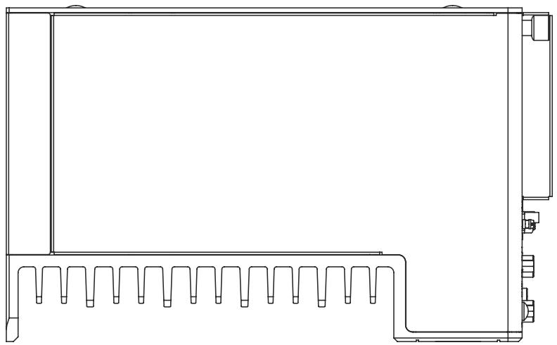
Figure 1-2: MXC-2300 Left Side View 6

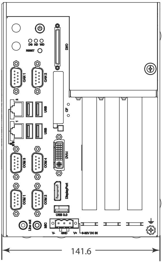
Figure 1-3: MXC-2300 Front View 7

Figure 1-4: MXC-2300 Top View 8

Figure 1-5: MXC-2300 Rear View....8

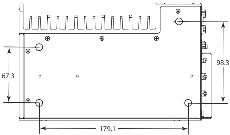
Figure 1-6: MXC-2300 Underside View 9

Figure 1-7: Front Panel I/O Connectors.... 10

Figure 1-8: Isolated Digital Input Circuit....15

Figure 1-9: Isolated Digital Input Differential Input Circuit...... 16

Figure 1-10: Isolated Digital Input Sample Application Circuit ..... 17

Figure 1-11: Isolated Digital Output Circuits .... 18

Figure 1-12: Isolated Digital Output Sample Application Circuit ... 18

Figure 1-13: CAN Port 19

Figure 1-14: DisplayPort Connector....23

Figure 1-15: Mainboard PCB 27

Figure 1-16: Backplane Board PCB 28

Figure 1-17: +5V and +12V Connector Pin Connector .... 29

This page intentionally left blank.

# 1 Introduction

# 1.1 Overview

Featuring the latest Intel® Atom™ E3845 Quad-core processor, the Matrix MXC-2300 series excels with minimal power consumption, exceptional 3D graphics, and powerful media acceleration, delivering leading improvements in performance and cost-efficiency over any previous generation Atom-based system.

Including dual-port CAN connectivity supported by a Phillips SJA1000 controller that can run independently or bridged at the same time, bus arbitration and error detection with auto-correction and re-transmission capability, and 16-CH isolated DI/O for general industrial control, the MXC-2300 features an increased total 3PCI/PCIe expansion slot count, supporting installation of a variety of off-the-shelf PCI/PCIe cards for configurable applications, and an internal PCI Express Mini Card socket and USIM slot support extension of additional functions, such as wireless connection.

In addition, the MXC-2300series offers one DisplayPort and one DVI-I port for dual independent display with full HD over HDMI, four USB 2.0 and one USB 3.0 ports, and 2 GbE LAN ports with teaming function.

With ADLINK's proprietary SEMA (Smart Embedded Management Agent) tool, the MXC-2300 maximizes manageability and security for a world of applications, providing efficient remote monitoring of system activity and health in real time, system control over a robust secured channel, and fully manageable complete utilization of system resources.

With ruggedized architecture, flexibility, and rich I/O capacity, the MXC-2300's minimal power consumption, abundant features, and leading performance and cost-efficiency make it the embedded system of choice for industrial automation, facility management, and intelligent transportation systems and applications demanding reliability in harsh environments.

# 1.2 Features

Intel® Atom™ E3845 processor with 4C @1.91 GHz SoC
▶ 2x DDR3L SO-DIMM, supporting up to 8GB memory
▶ 2 PCI + 1 PCIe x4 or 3 PCI expansion slots
▶ Built-in dual-port isolated CAN and 16-CH isolated DI and DO
▶ 1 DisplayPort + 1 DVI-I
▶ 2 Intel GbE ports with teaming function, 1 USB 3.0 + 4 USB 2.0 ports
▶ 1 external CF slot and 1 internal PCIe Mini Card socket with USIM socket
▶ 2 software-programmable RS-232/422/485 + 2 RS-232 ports
▶ Built-in 9 to 32 VDC wide-range DC power input
▶ Rugged, -20°C to 70°C fanless operation (w/ industrial SSD)
▶ Built-in ADLINK SEMA 1.0 (Smart Embedded Management Agent))

![The image shows a white document icon with a folded top-right corner. It features faint horizontal gray lines and a large, bold red checkmark drawn diagonally across the center.](.mxc-2300-50-1z159-1000-200-y151008-en/7ca5e9dfc8f9f3e32d0214ed36f817fc52561e819fab5d72f80d1c6248c488dd.jpg)
NOTE:

This option guarantees cold boot of the system at $-20^{\circ}$ C and operation with 100% loading at $60^{\circ}$ without add-on cards. The industrial solid-state drive storage option is required.

# 1.3 Specifications

<table><tr><td></td><td>MXC-2300CD-3E1</td><td>MXC-2300CD-3S</td><td>MXC-2300-3E1</td><td>MXC-2300-3S</td></tr><tr><td colspan="5">System Core</td></tr><tr><td>Processor</td><td colspan="4">Intel® AtomTM Processor E3845 (Bay Trail-I Premium)4C @ 1.91GHz CPU</td></tr><tr><td>Chipset</td><td colspan="4">Intel SoC (System on Chip)</td></tr><tr><td>Video</td><td colspan="4">1 DisplayPort +1 DVI-I (VGA or DVI-D)DP: resolution up to 2560x1600VGA: resolution up to 1600x1200</td></tr><tr><td>Memory</td><td colspan="4">4GB DDR3L 1333MHz SODIMM module, (up to 8GB with 2 SODIMM sockets)</td></tr><tr><td colspan="5">I/O Interface</td></tr><tr><td>Expansion slots</td><td>2 PCI+1 PCIe x4</td><td>3 PCI</td><td>2 PCI+1 PCIe x4</td><td>3 PCI</td></tr><tr><td>Ethernet</td><td colspan="4">2 Intel® GbE ports (Intel® Springville WGI210IT chipset)Teaming function, Wake On LAN</td></tr><tr><td>Serial Ports</td><td colspan="4">2 software-programmable RS-232/422/485 (COM 1&amp;2) with auto-flow control, 2 RS-232 (COM 3&amp;4)</td></tr><tr><td>USB</td><td colspan="4">5 external USB ports (4 USB 2.0 + 1 USB 3.0) + 1 internal USB 2 .0</td></tr><tr><td>CAN</td><td colspan="2">2 DB9 isolated CAN port with SjA1000 CAN controller</td><td colspan="2">-</td></tr><tr><td>DIO</td><td colspan="2">16-CH DI and 16-CH DO with 1.5KV isolation</td><td colspan="2">-</td></tr><tr><td>Mini PCIe</td><td colspan="2">1 internal mini PCIe card socket</td><td colspan="2">-</td></tr><tr><td>USIM</td><td colspan="2">1 USIM socket for 3G communication</td><td colspan="2">-</td></tr><tr><td>Audio</td><td colspan="4">1 MIC-in and 1 Line-out</td></tr><tr><td colspan="5">Power Supply</td></tr><tr><td>DC Input</td><td colspan="4">Built-in 9-32  $V_{DC}$  wide-range DC input pluggable connectors with latch (GND, V-, V+), 2-pin remote power on/off switch</td></tr><tr><td>AC Input</td><td colspan="4">Optional 100 W external AC-DC adapter for AC input</td></tr><tr><td colspan="5">Storage</td></tr><tr><td>SATA HDD</td><td colspan="4">Onboard SATA-II port for 2.5” HDD/SSD installation</td></tr><tr><td>CompactFlash</td><td colspan="4">1 CompactFlash socket</td></tr><tr><td colspan="5">Mechanical</td></tr><tr><td>Optional Fan Module</td><td colspan="4">Optional fan module for heat dissipation, smart fan control</td></tr><tr><td>Dimensions</td><td colspan="4">142 (W) x219 (D) x210(H) mm (WxDxH) (5.84” x 8.76” x 8.4)</td></tr><tr><td>Weight</td><td colspan="4">3.5 kg</td></tr><tr><td>Mounting</td><td colspan="4">Wall-mount kit</td></tr><tr><td colspan="5">Environmental</td></tr><tr><td>Operating Temperature</td><td colspan="4">Standard: 0°C to 50°C (32°F to 122°F)Extended Temperature: -20°C to 70°C (-4°F to 158°F) (w/industrial SSD or CF)</td></tr><tr><td>Storage Temperature</td><td colspan="4">-40°C to 85°C (-40°F to 185°F) (excl. HDD/SDD/CF)</td></tr><tr><td>Humidity</td><td colspan="4">~95% @ 40°C (104°F) (non-condensing)</td></tr><tr><td>Vibration</td><td colspan="4">Operating, 5 Grms, 5-500 Hz, 3 axes (w/ CF or SSD)Operating, 0.5 Grms, 5-500 Hz, 3 axes (w/ HDD)</td></tr><tr><td>ESD</td><td colspan="4">Contact +/-4 KV and Air +/-8 KV</td></tr><tr><td>Shock</td><td colspan="4">Operating, 50 G, half sine 11 ms duration (w/ CF or SSD)</td></tr><tr><td>EMC</td><td colspan="4">CE and FCC Class A</td></tr><tr><td>Safety</td><td colspan="4">UL/cULUL 60950-1 &amp; CAN/CSA-C22.2 #60950-1, UL report#A48-UL</td></tr></table>

![A white document icon with horizontal lines and a folded corner, featuring a large red checkmark overlaid on it.](.mxc-2300-50-1z159-1000-200-y151008-en/8a215c0d5bd35f6b603cbe2bdd15e6b6169b15102bb40f454c946404b6f43810.jpg)
NOTE:

Extending operating temperature to the $-20^{\circ}C$ to $+70^{\circ}C$ range is optional and requires an industrial solid-state storage drive.
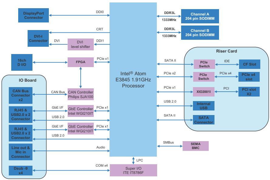
![The diagram is a block diagram centered around the **Intel® Atom E3845 1.91GHz Processor**.\n\n**Left-Side Connections (Video and IO Board):**\n*   The processor connects via **DDI0** to the **DisplayPort Connector**.\n*   The processor connects via **CRT**.\n*   The processor connects via **DDI1** to the **DVI level shifter**, which connects via **DVI** to the **DVI-I Connector**.\n*   The processor connects via **PCIe x1** to the **FPGA**.\n    *   The **FPGA** connects to the **16ch D I/O**.\n    *   The **FPGA** connects to the **CAN Controller Philips SJA100**.\n    *   The **CAN Controller Philips SJA100** connects via **CAN Bus** to the **CAN Bus Connector x2**.\n*   The processor connects via **PCIe x1** to the **GbE Controller Intel WGI210IT**.\n    *   This controller connects via **GbE I/F** and **USB 2.0** to the **RJ45 & USB2.0 x 2 Connector**.\n*   The processor connects via **PCIe x1** to a second **GbE Controller Intel WGI210IT**.\n    *   This controller connects via **GbE I/F** and **USB 2.0** to a second **RJ45 & USB2.0 x 2 Connector**.\n*   The processor connects via **Audio** to the **Line out & Mic in Connector**.\n*   The processor connects via **COM x4** to the **Super I/O ITE IT8786F**.\n\n**Right-Side Connections (Memory and Riser Card):**\n*   The processor connects via **DDR3L 1333MHz** to the **Channel A 204 pin SODIMM**.\n*   The processor connects via **DDR3L 1333MHz** to the **Channel B 204 pin SODIMM**.\n*   The processor connects via **SATA II** to the **SATA Connector** (located inside the **Riser Card** group).\n*   The processor connects via **PCIe x2** to the top **PCIe Switch** (inside **Riser Card**).\n    *   This switch connects via **IDE** to the **CF Slot**.\n*   The processor connects via **PCIe x2** to the middle **PCIe Switch** (inside **Riser Card**).\n    *   This switch connects via **PCIe x4** to the **PCIe x4 slot**.\n*   The processor connects via **PCIe x1** to the **XIO2001I** (inside **Riser Card**).\n    *   This component connects via **PCI** to the **PCI slot X2**.\n*   The processor connects via **USB 2.0** to the **Internal USB** (inside **Riser Card**).\n\n**Bottom and Peripheral Connections:**\n*   The **Super I/O ITE IT8786F** connects via **LPC** (arrow points upward to processor).\n*   The processor connects via **SMBus** to the **SEMA BMC**.](.mxc-2300-50-1z159-1000-200-y151008-en/834b61e8c71a2600794400cdbb50f8c005302f12fff4ee82d06c1a04a895a2fa.jpg)

Figure 1-1: MXC-2300 Functional Block Diagram

# 1.4 Schematics and Dimensions

![The image shows a simple icon depicting a white document or piece of paper with a folded top-right corner. Horizontal gray lines run across the page, suggesting a list or text. A large, bold red checkmark (or tick) is superimposed over the center, running diagonally from the bottom left to the top right.](.mxc-2300-50-1z159-1000-200-y151008-en/a8e73a18cdc5dadb5917a523ca2525c0f4f9581d2ec2c1a6fee2c2df96506915.jpg)
NOTE:

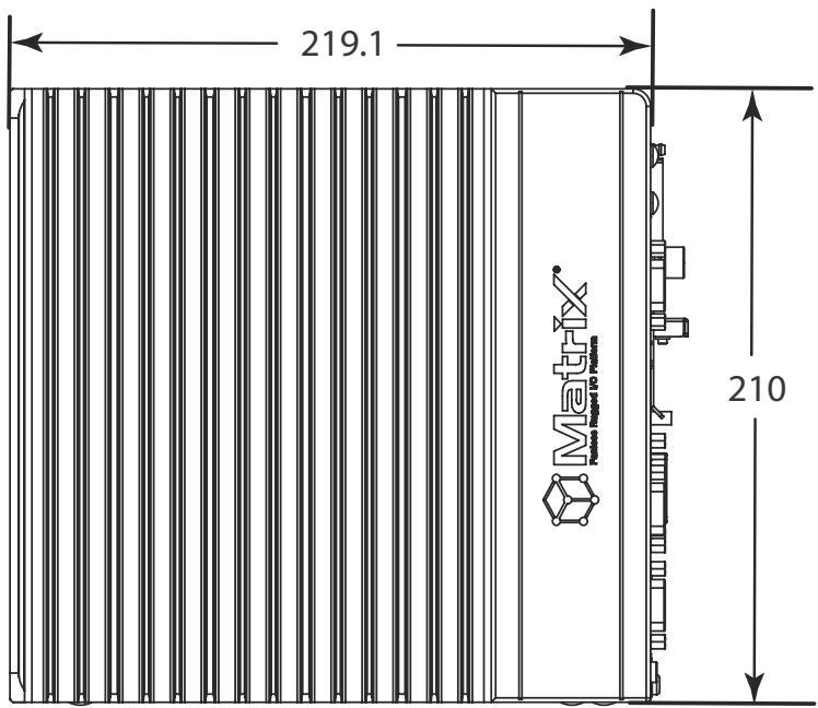
All dimensions shown are in mm (millimeters).
![219.1\nMatrix\nMatrix\n210](.mxc-2300-50-1z159-1000-200-y151008-en/3e9e9cc3c7fdd961e7bc02bd20adce8bdb1893d46d58112058b531f095f57a6c.jpg)

Figure 1-2: MXC-2300 Left Side View

![DO HD VD\nRESET\nCAN 1 CAN 2\nUSB\nUSB\nCOM 3 COM 4 DV-1\nCOM 1 COM 2 Display/Port\nUSB 3.0\nLine out MRC V- OND V+ 0-82V DC IN\n141.6](.mxc-2300-50-1z159-1000-200-y151008-en/3fba0291bf05d0fed2e587c1d64db2084bf74718f064822d852e3c50b9589702.jpg)

Figure 1-3: MXC-2300 Front View

![Technical line drawing of a mechanical component with slots and mounting brackets (no text or symbols)](.mxc-2300-50-1z159-1000-200-y151008-en/eacf2f79d2685e996396c100dc8de9df432b7a51e6af80c7bb7691f396fbd3cd.jpg)

Figure 1-4: MXC-2300 Top View

![Pure electrical circuit lines without any symbols](.mxc-2300-50-1z159-1000-200-y151008-en/8f5422f470a011abeceebf5f52d30a5008a41acbe03c4a10bb5fd45d8135d1b9.jpg)

Figure 1-5: MXC-2300 Rear View

![67.3\n179.1\n98.3](.mxc-2300-50-1z159-1000-200-y151008-en/6cc805630955c82adb6ebebfe839db3eaa976559816e41a90a24e403a5f2c8f6.jpg)

Figure 1-6: MXC-2300 Underside View

# 1.5 Front Panel I/O Connectors
![ADLINK\nTECHNOLOGY INC.\nA\nB\nC\nD\nE\nF\nG\nH\nI\nJ\nK\nL\nM\nN\nO\nP\nDAC\nCF HD WD\nCAN 1 CAN 2\nUSB\nUSB\nCOM 3 COM 4\nCOM 1 COM 2\nUSB 3.0\nLink Out MIC\nV- GND V+ -9-32V DC IN](.mxc-2300-50-1z159-1000-200-y151008-en/b491e5fe1e253c45c183dadfbb0a30bfaae079e6e00a682c866d94da70af5237.jpg)

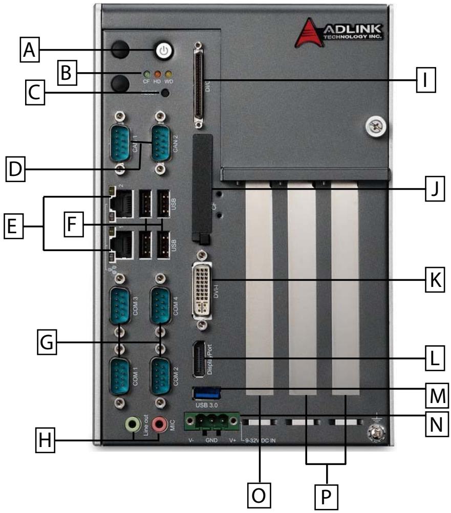
Figure 1-7: Front Panel I/O Connectors

<table><tr><td>A</td><td>Power Button</td><td>I</td><td>Digital I/O connector</td></tr><tr><td>B</td><td>LED Indicators</td><td>J</td><td>Compact-Flash slot</td></tr><tr><td>C</td><td>Reset Button</td><td>K</td><td>DVI-I connector</td></tr><tr><td>D</td><td>DB9 CAN Bus x2</td><td>L</td><td>DisplayPort connector</td></tr><tr><td>E</td><td>GbE x2</td><td>M</td><td>USB3.0 connector</td></tr><tr><td>F</td><td>USB2.0 connector x4</td><td>N</td><td>DC power supply connector</td></tr><tr><td>G</td><td>COM port x4</td><td>O</td><td>PCIe x4slot x 1 (MXC-2300-3E1)5V 32-Bit PCI slot (MXC-2300-3S)</td></tr><tr><td>H</td><td>Audio Jacks</td><td>P</td><td>5V 32-Bit PCI slots x 2</td></tr></table>

Table 1-1: Front Panel I/O Connector Legend

# 1.5.1 Power Button

The power button is a non-latched push button with a blue LED indicator. System is turned on when the button is depressed, and the power LED lights. If the system hangs, depress the button for 5 seconds to turn off the system completely.

# 1.5.2 LED Indicators

In addition to the LED of the power button, three LEDs on the front panel indicate the following.

<table><tr><td>LED indicator</td><td>Color</td><td>Description</td></tr><tr><td>Watchdog (WD)</td><td>Yellow</td><td>Indicates watchdog timer status. When watchdog timer starts, the LED flashes. When the timer is expired, the LED remains lit..</td></tr><tr><td>Hard disk drive (HD)</td><td>Red</td><td>Indicates the HDD operating state. When the SATA hard drive or CFast card is active, the LED indicator flashes.</td></tr><tr><td>Diagnostic (DG)</td><td>Green</td><td>When lit continuously, indicates no physical storage is connected, and if blinking, indicates no memory is installed on either SODIMM socket.</td></tr></table>

Table 1-2: LED Indicators

# 1.5.3 Reset Button

The reset button executes a hard reset for the MXC-2300.

# 1.6 Digital I/O Connector

The MXC-2300 controller features an onboard isolated digital I/O circuit with a 68-pin VHDCI (Very High Density Cable Interconnect) connector on the front panel. The onboard digital I/O card supports the following features:

# 16-CH Isolated DI

▶ Logic high: 5 to 24 V
▶ Logic low: 0 to 1.5 V
▶ Input resistance: 8.2K @ 0.75W
▶ Isolation type: photocoupler
▶ Isolation voltage: 1500 V DC

# 16-CH Isolated DO

▶ Output Type: MOSFET transistor

▶ Sink current up to 100 mA (sustained loading) or 250 mA (peak loading) on each isolated output channel
▶ Supply voltage: 5 to 35 V DC
▶ Isolation type: Digital Isolator
▶ Isolation voltage: 1500 V DC
▶ Flywheel diode for VDD on all DO channels

# Isolated 5V DC Power Source for DO

▶ Supply voltage: 5 ± 0.5V DC
▶ Supply current: 180 mA (maximum)
▶ Isolation type: DC-to-DC transformer
▶ Isolation voltage: 1500 VRMS (channel to system)

# General Specification

▶ 68-pin VHDCI (Very High Density Cable Interconnect) connector (mating with AMP 787082-7) on the front panel
▶ Optional accessories: DIN-68S-01 and ACL-10568-1
▶ Data transfer: programmed IO
▶ Software Driver support: please download from our website

<table><tr><td></td><td>Pin</td><td>Signal</td><td>Pin</td><td>Signal</td><td>Pin</td><td>Signal</td></tr><tr><td rowspan="23">&lt;img src="images/f6cb52dcb0bdbc3da0ceacbb274c6588b7015a44e71636175b47dbc9a4037044.jpg"/&gt;</td><td>1</td><td>+VDD</td><td>24</td><td>DI1_L</td><td>47</td><td>EOGND</td></tr><tr><td>2</td><td>EOGND</td><td>25</td><td>DI0_H</td><td>48</td><td>DO10</td></tr><tr><td>3</td><td>DO7</td><td>26</td><td>DI0_L</td><td>49</td><td>EOGND</td></tr><tr><td>4</td><td>EOGND</td><td>27</td><td>DI11</td><td>50</td><td>DO9</td></tr><tr><td>5</td><td>DO6</td><td>28</td><td>ISO_COM</td><td>51</td><td>EOGND</td></tr><tr><td>6</td><td>EOGND</td><td>29</td><td>DI10</td><td>52</td><td>DO8</td></tr><tr><td>7</td><td>DO5</td><td>30</td><td>ISO_COM</td><td>53</td><td>DI7_H</td></tr><tr><td>8</td><td>EOGND</td><td>31</td><td>DI9</td><td>54</td><td>DI7_L</td></tr><tr><td>9</td><td>DO4</td><td>32</td><td>ISO_COM</td><td>55</td><td>DI6_H</td></tr><tr><td>10</td><td>EOGND</td><td>33</td><td>DI8</td><td>56</td><td>DI6_L</td></tr><tr><td>11</td><td>DO3</td><td>34</td><td>ISO_COM</td><td>57</td><td>DI5_H</td></tr><tr><td>12</td><td>EOGND</td><td>35</td><td>+VDD</td><td>58</td><td>DI5_L</td></tr><tr><td>13</td><td>DO2</td><td>36</td><td>+V5DIO_CN_ISO</td><td>59</td><td>DI4_H</td></tr><tr><td>14</td><td>EOGND</td><td>37</td><td>EOGND</td><td>60</td><td>DI4_L</td></tr><tr><td>15</td><td>DO1</td><td>38</td><td>DO15</td><td>61</td><td>DI15</td></tr><tr><td>16</td><td>EOGND</td><td>39</td><td>EOGND</td><td>62</td><td>ISO_COM</td></tr><tr><td>17</td><td>DO0</td><td>40</td><td>DO14</td><td>63</td><td>DI14</td></tr><tr><td>18</td><td>EOGND</td><td>41</td><td>EOGND</td><td>64</td><td>ISO_COM</td></tr><tr><td>19</td><td>DI3_H</td><td>42</td><td>DO13</td><td>65</td><td>DI13</td></tr><tr><td>20</td><td>DI3_L</td><td>43</td><td>EOGND</td><td>66</td><td>ISO_COM</td></tr><tr><td>21</td><td>DI2_H</td><td>44</td><td>DO12</td><td>67</td><td>DI12</td></tr><tr><td>22</td><td>DI2_L</td><td>45</td><td>EOGND</td><td>68</td><td>ISO_COM</td></tr><tr><td>23</td><td>DI1_H</td><td>46</td><td>DO11</td><td></td><td></td></tr></table>

Table 1-3: Digital I/O Connector Pin Signals

<table><tr><td rowspan="4">DI</td><td>DIn_H</td><td>High input of isolated differential DI channel (n=0 to 7)</td></tr><tr><td>DIn_L</td><td>Low input of isolated differential DI channel (n=0 to 7)</td></tr><tr><td>DIn</td><td>Input of isolated DI channel (n=8 to 15)</td></tr><tr><td>ISO_COM</td><td>Common ground of isolated DI channel 8 to 15</td></tr><tr><td rowspan="4">DO</td><td>DOn</td><td>Output of isolated DO channel (n=0 to 15)</td></tr><tr><td>EOGND</td><td>Ground return path of isolated DO channel 0 to 15 and +V5DIO_CN_ISO</td></tr><tr><td>+VDD</td><td>Power input signal for flywheel diode of isolated DO channel 0 to 15</td></tr><tr><td>+V5DIO_CN_ISO</td><td>Isolated 5V DC power, maximum output 180mA</td></tr></table>

Table 1-4: Digital I/O Connector Pin Legend

# 1.6.1 Isolated Digital Input Circuits

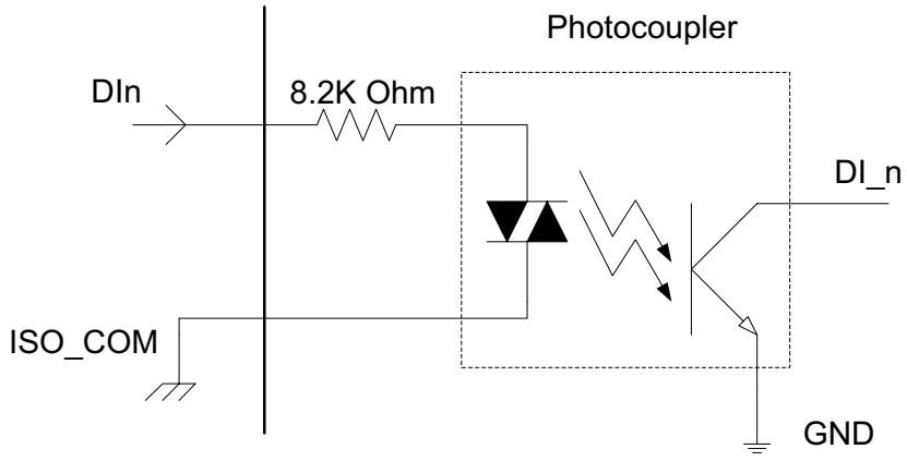
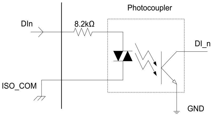
Input accepts voltages up to 24V, with input resistors of 8.2 kΩ, with connections between outside signals as shown.
![DIn\n8.2K Ohm\nPhotocoupler\nDI_n\nISO_COM\nGND](.mxc-2300-50-1z159-1000-200-y151008-en/18df0110df1025c2dbd971d29487b33d673214c3e6dead53afcc89661f56e56b.jpg)

Figure 1-8: Isolated Digital Input Circuit
![DIn\n8.2kΩ\nPhotocoupler\nDI_n\nISO_COM\nGND](.mxc-2300-50-1z159-1000-200-y151008-en/495edfc30e1de3daeb688e1d1c599daf3c4bccfcd9615268fd0793b63a13dcea.jpg)

Figure 1-9: Isolated Digital Input Differential Input Circuit
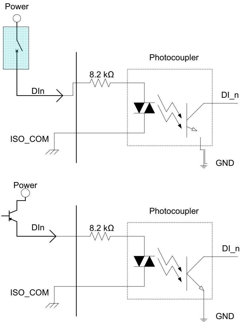
![The image displays two electronic circuit diagrams arranged vertically. Both schematics depict a digital input circuit utilizing a photocoupler (optocoupler) for signal isolation across a barrier (indicated by a vertical line).\n\n**Top Diagram:**\n- **Input Side (Left):** A light blue box labeled '**Power**' contains a switch symbol. A line labeled '**DIn**' extends from the switch to the right.\n- **Components:** The line passes through a resistor labeled '**8.2 kΩ**'.\n- **Photocoupler:** A dashed box labeled '**Photocoupler**' contains the isolated components. The input side features a bidirectional LED symbol (two diodes in anti-parallel) connected to a line labeled '**ISO_COM**', which is grounded.\n- **Output Side (Right):** Inside the box, zigzag arrows indicate optical coupling to a phototransistor. The phototransistor's collector connects to an output line labeled '**DI_n**'. The emitter connects to a ground symbol labeled '**GND**'.\n\n**Bottom Diagram:**\n- **Input Side (Left):** A circle labeled '**Power**' connects to a transistor-like switch symbol. A line labeled '**DIn**' extends from the transistor to the right.\n- **Components:** The circuit continues identically to the top diagram, with the '**DIn**' line connecting to the '**8.2 kΩ**' resistor.\n- **Photocoupler & Output:** The '**Photocoupler**' box and its connections are identical to the top diagram, with the output labeled '**DI_n**' and ground labeled '**GND**'.\n\n**Text present in the image:**\n- Power\n- DIn\n- ISO_COM\n- 8.2 kΩ\n- Photocoupler\n- DI_n\n- GND](.mxc-2300-50-1z159-1000-200-y151008-en/0b20e412b5c03ba9f53017162101eb31c052e1507ba705ccd12e5047ab7e3cb5.jpg)
Figure 1-10: Isolated Digital Input Sample Application Circuit

# 1.6.2 Isolated Digital Output Circuits

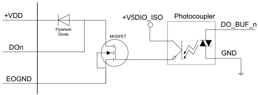
Each isolation digital output channel adopts a MOSFET transistor, capable of driving peak current up to 250mA (sustained current up to 100 mA) with voltage ranges from 5V to 35V.

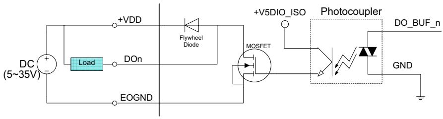
The VDD pin is connected in serial with a flywheel diode protecting the driver during inductance loading, such as relay, motor, or sole-noid, wherein the VDD must connect to external power to form a flywheel current loop.
![+VDD\nFlywheel\nDiode\n+V5DIO_ISO\nPhotocoupler\nDO_BUF_n\nDOn\nMOSFET\nEOGND\nGND](.mxc-2300-50-1z159-1000-200-y151008-en/1ac1bdd724292799a6001a323872e7d31d70cd9997a4bff59caf610ea2c579fe.jpg)

Figure 1-11: Isolated Digital Output Circuits
![DC\n(5~35V)\n+\n-\nLoad\nDOn\nEOGND\n+VDD\nFlywheel\nDiode\nMOSFET\n+V5DIO_ISO\nPhotocoupler\nDO_BUF_n\nGND](.mxc-2300-50-1z159-1000-200-y151008-en/37289085a8840939699f57f827c567976e2d8e887ff40139e7a4464d0df8c981.jpg)

Figure 1-12: Isolated Digital Output Sample Application Circuit

# 1.6.3 Digital I/O Windows Driver and API

The MXC-2300 DI/O incorporates ADLINK's PCMe-1432 Windows driver, on the bundled driver CD or downloadable from Adlink's MXC-2300 web support page (driver for MXC-2300 DI/O).

# 1.6.4 Controller Area Network (CAN) Port
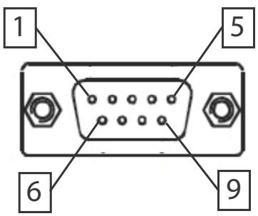
![1\n5\n6\n9](.mxc-2300-50-1z159-1000-200-y151008-en/dd8696b3863b0c3c4cabdcef153da39465f66ac1019d416fcf6594bbd643f9c0.jpg)

Figure 1-13: CAN Port

<table><tr><td>Pin</td><td>Signal</td><td>Pin</td><td>Signal</td></tr><tr><td>1</td><td>N/A</td><td>6</td><td>N/A</td></tr><tr><td>2</td><td>CAN_L</td><td>7</td><td>CAN_H</td></tr><tr><td>3</td><td>GND</td><td>8</td><td>N/A</td></tr><tr><td>4</td><td>N/A</td><td>9</td><td>N/A</td></tr><tr><td>5</td><td>N/A</td><td></td><td></td></tr></table>

Table 1-5: CAN Port Pin Assignments

The Controller Area Network (CAN) interface supports dual-port isolated CAN connection that can run independently or bridged at the same time. The built-in CAN controller is a Phillips SJA1000, providing bus arbitration and error detection with auto correction and re-transmission capability, and features:

▶ Dual independent CAN network operation
▶ Bridge function support
▶ Compatibility with CAN specification 2.0 parts A and B
▶ Optically isolated CAN interface with up to 1000 Vrms isolation protection
▶ Direct memory mapping to CAN controllers
▶ CAN controller bit rate up to 1Mbits/s

▶ Powerful master interface for CANopen, DeviceNet and SDS application layer protocol

# 1.6.5 USB 2.0 Ports

The MXC-2300 provides four USB 2.0 ports supporting Type A USB connection on the front panel. All USB ports are compatible with high-speed, full-speed and low-speed USB devices. The MXC-2300 supports multiple boot devices, including USB flash drive, USB external hard drive, USB floppy, USB CD-ROM and others. The boot priority and boot device can be configured in BIOS. Please refer to Section B.4: Security on page 82 for details.

# 1.6.6 USB 3.0 Ports

The MXC-2300 provides a USB 3.0 port supporting Type A USB 3.0 connection on the front panel, compatible with super-speed, high-speed, full-speed and low-speed USB devices.

# 1.6.7 Gigabit Ethernet Ports

The MXC-2300 has two Gigabit Ethernet ports on the front panel, supporting the Intel WGI210IT GbE controller, which provides:

▶ IEEE 802.3az Energy Efficient Ethernet
▶ IEEE 1588/802.1AS precision time synchronization
▶ IEEE 802.3Qav traffic shaper
▶ Interrupt moderation, VLAN support, IP checksum offload
▶ PCIe OBFF (Optimized Buffer Flush/Fill) for improved system power management
▶ Four transmit and four receive queues
▶ RSS and MSI-X to lower CPU utilization in multi-core systems
▶ ECC - error correcting memory in packet buffers
▶ Wake-On-LAN
▶ NC-SI for increased bandwidth passthrough
▶ Preboot eXecution Environment (PXE) flash interface
▶ Jumbo frame support
▶ LAN Teaming

![Close-up of a black electronic device with three ports and a small symbol below (no readable text or labels)](.mxc-2300-50-1z159-1000-200-y151008-en/1c50f351dbdc7df89914cd15299f37c141e78f9cf1538203c55cad88ff992b79.jpg)

<table><tr><td>Active/LinkYellow</td><td>Speed LEDGreen/Orange</td></tr></table>

<table><tr><td>LED Color</td><td>Status</td><td>Description</td></tr><tr><td rowspan="3">Yellow</td><td>OFF</td><td>Ethernet port is disconnected.</td></tr><tr><td>ON</td><td>Ethernet port is connected with no activity.</td></tr><tr><td>Flashing</td><td>Ethernet port is connected and active.</td></tr></table>

Table 1-6: Active/Link LED

<table><tr><td>LED Color</td><td>Status</td><td>Description</td></tr><tr><td rowspan="3">Green/Orange</td><td>OFF</td><td>10 Mbps</td></tr><tr><td>Green</td><td>100 Mbps</td></tr><tr><td>Orange</td><td>1000 Mbps</td></tr></table>

Table 1-7: Speed LED

# 1.6.8 Compact Flash Socket

A Type I Compact-Flash socket provides +3.3V voltage to a CF card. The CF interface is transferred from SATA by an ASIC, and can be an alternative storage device for system installation. The MXC-2300 can boot via a CF card with OS installed. Due to the nature of the SATA interface, the CF card cannot hot-plug and must be installed before powering up the system.

# 1.6.9 DVI-I Connector

The MXC-2300 provides one DVI-I connector providing connection to an external monitor.

![The image displays a standard warning sign featuring a yellow triangle with rounded corners containing a black exclamation point. Below the triangle, the text 'CAUTION:' is printed in black capital letters on a white background.](.mxc-2300-50-1z159-1000-200-y151008-en/66e71133c69ccfd8895164f0e70dc79cb9a4da724507f5b5754d060752eb3f2c.jpg)

Since VGA signals are analog based, VGA display quality is greatly affected by quality and length of cable used. We strongly recommended VGA cable less than 2 meters in length with effective shielding, such as UL style 2919 AWM.

![1 2 3 4 5 6 7 8\n9 10 11 12 13 14 15 16\n17 18 19 20 21 22 23 24\nC1 C2\nC3 C4\nC5](.mxc-2300-50-1z159-1000-200-y151008-en/80937c8cf9c45d26c476a0f02b34ac66561fa9ce6fe89f347daa2e906cfe4236.jpg)

<table><tr><td>Pin</td><td>Signal</td><td>Pin</td><td>Signal</td><td>Pin</td><td>Signal</td><td>Pin</td><td>Signal</td></tr><tr><td>1</td><td>DVldata 2-</td><td>9</td><td>DVldata 1-</td><td>17</td><td>DVldata 0-</td><td>C1</td><td>Analog Red</td></tr><tr><td>2</td><td>DVldata 2+</td><td>10</td><td>DVldata 1+</td><td>18</td><td>DVldata 0+</td><td>C2</td><td>Analog Green</td></tr><tr><td>3</td><td>GND</td><td>11</td><td>GND</td><td>19</td><td>GND</td><td>C3</td><td>Analog Blue</td></tr><tr><td>4</td><td>CRT DDC clock</td><td>12</td><td>N/C</td><td>20</td><td>N/C</td><td>C4</td><td>Analog horiz. sync</td></tr><tr><td>5</td><td>CRT DDC data</td><td>13</td><td>N/C</td><td>21</td><td>N/C</td><td>C5</td><td>Analog GND</td></tr><tr><td>6</td><td>DVIDC clock</td><td>14</td><td>+5V</td><td>22</td><td>GND</td><td></td><td></td></tr><tr><td>7</td><td>DVIDC data</td><td>15</td><td>GND</td><td>23</td><td>DVI clock +</td><td></td><td></td></tr><tr><td>8</td><td>Analog vert. sync</td><td>16</td><td>Hot plug detect</td><td>24</td><td>DVI clock -</td><td></td><td></td></tr></table>

Table 1-8: DVI-I Connector Signals

# 1.6.10 COM Port Connectors

The MXC-2300 provides four COM ports through D-sub 9 pin connectors. The COM1 & COM2 ports support RS-232/422/485 modes by BIOS setting, while COM3 and COM4 support only RS-232.

![1\n5\n6\n9](.mxc-2300-50-1z159-1000-200-y151008-en/56437c4edddeee5bd22edb501b2cc3306f472fa192f87b52ad4c6b8cd7ec4dca.jpg)

<table><tr><td rowspan="2">Pin</td><td colspan="3">Signal Name</td></tr><tr><td>RS-232</td><td>RS-422</td><td>RS-485</td></tr><tr><td>1</td><td>DCD#</td><td>TXD422-</td><td>485DATA-</td></tr><tr><td>2</td><td>RXD</td><td>TXD422+</td><td>485DATA+</td></tr><tr><td>3</td><td>TXD</td><td>RXD422+</td><td>N/S</td></tr><tr><td>4</td><td>DTR#</td><td>RXD422-</td><td>N/S</td></tr><tr><td>5</td><td>GND</td><td>N/S</td><td>N/S</td></tr><tr><td>6</td><td>DSR#</td><td>N/S</td><td>N/S</td></tr><tr><td>7</td><td>RTS#</td><td>N/S</td><td>N/S</td></tr><tr><td>8</td><td>CTS#</td><td>N/S</td><td>N/S</td></tr><tr><td>9</td><td>RI#</td><td>N/S</td><td>N/S</td></tr></table>

Table 1-9: D-Sub 9p Signal Function of Com Ports

# 1.6.11 DisplayPort Connectors

Two displayport connectors on the front panel can connect to VGA, DVI, HDMI and DisplayPort monitors via DisplayPort to VGA adapter cable, DisplayPort to DVI adapter cable, or DisplayPort to HDMI adapter cable and DisplayPort cable.

![19\n1\n20\n2](.mxc-2300-50-1z159-1000-200-y151008-en/46e7de1747527891972ef1591e12aabfd9aa63fd6c83d9a012a6ea1bbc522a4b.jpg)

Figure 1-14: DisplayPort Connector

<table><tr><td>Pin</td><td>Signal</td><td>Pin</td><td>Signal</td></tr><tr><td>1</td><td>CN_DDPx0+</td><td>11</td><td>GND</td></tr><tr><td>2</td><td>GND</td><td>12</td><td>CN_DDPx3-</td></tr><tr><td>3</td><td>CN_DDPx0-</td><td>13</td><td>CN_DDPx_AUX_SEL</td></tr><tr><td>4</td><td>CN_DDPx1+</td><td>14</td><td>CN_DDPx_CONFIG2</td></tr><tr><td>5</td><td>GND</td><td>15</td><td>CN_DDPx_AUX+</td></tr><tr><td>6</td><td>CN_DDPx1-</td><td>16</td><td>GND</td></tr><tr><td>7</td><td>CN_DDPx2+</td><td>17</td><td>CN_DDPx_AUX-</td></tr><tr><td>8</td><td>GND</td><td>18</td><td>CN_DDPx_HPD</td></tr><tr><td>9</td><td>CN_DDPx2-</td><td>19</td><td>GND</td></tr><tr><td>10</td><td>CN_DDPx3+</td><td>20</td><td>+V3.3_DDPx_PWR_CN</td></tr></table>

Table 1-10: DisplayPort Pin Assignments

<table><tr><td>P/N</td><td>Description</td></tr><tr><td>30-01119-0000</td><td>Passive DisplayPort to HDMI adapter cable</td></tr><tr><td>30-01120-0000</td><td>Passive DisplayPort to DVI adapter cable</td></tr><tr><td>30-01121-0000</td><td>Passive DisplayPort to VGA adapter cable</td></tr><tr><td>30-01157-0000</td><td>Active DisplayPort to DVI adapter cable</td></tr></table>

Table 1-11: Applicable Cable Types

# 1.6.12 Audio Jacks

The MXC-2300 implements Intel High Definition audio on a Realtek ALC269 chip. The HD audio supports up to 24-bit, 192 KHz sample rate high quality headphone/line out and microphone input. Audio jack access is on the front panel. The pink jack provides microphone input, and the green jack line out.

![The image displays a close-up of a green circuit board featuring two vertically aligned audio jacks. The top jack has a green ring around it and is labeled 'SPK' in black capital letters. Below it is a second jack with a pink ring around it, labeled 'MIC' in black capital letters.](.mxc-2300-50-1z159-1000-200-y151008-en/2934ec97e38c3768252c1551c58f755944421991a0b6bd81f5324f840cd8af2a.jpg)

<table><tr><td>Color</td><td>Signal</td></tr><tr><td>Green</td><td>lineout</td></tr><tr><td>Pink</td><td>Mic In</td></tr></table>

Table 1-12: Audio Jack Signals

# 1.6.13 DC Power Connector

The DC power supply connector of the MXC-2300 is on the front panel. The power supply connector consists of three pins, V+, chassis ground, and V- from right to left respectively. V+ and V-pins provide DC power input and the chassis ground pin allows connection of the chassis to ground for better EMC compatibility. The DC power input for the MXC-2300 allows a voltage input range from 9 V DC to 32 V DC.

![The image shows a standard warning sign. It features a red triangle with rounded corners containing a black exclamation point in the center. Below the triangle, the text 'WARNING:' is printed in black, uppercase letters. The sign is set against a white background, flanked by black vertical bars on the left and right sides.](.mxc-2300-50-1z159-1000-200-y151008-en/df27a8bdc6154c20a81d8b8536a5ebc46c373164445475d0d4e52f66c5e95708.jpg)

Ensure that the DC power supply:

▶ is within the input voltage range defined in the specification
▶ is stable and low-noise DC
▶ provides sufficient operating current

DC power supply over or under voltage, unstable, or of insufficient power may cause system instability and physical damage

![9V~32V DC IN\nV- GND V+](.mxc-2300-50-1z159-1000-200-y151008-en/a19f8a0b39cfd833dbddde1b026e51d272ad96ab9c82276e6b53c378ad813f2d.jpg)

<table><tr><td>Pin</td><td>Signal</td></tr><tr><td>1</td><td>V+ (DC_IN)</td></tr><tr><td>2</td><td>GND (CHGND)</td></tr><tr><td>3</td><td>V- (DGND)</td></tr></table>

Table 1-13: DC Power Supply Connector Signals

# 1.6.14 PCI Slot

The MXC-2300 provides two PCI slots, based on the PCIe to PCI bridge, with connection to the host system achieved through a PCIe interface, supporting universal or 5V PCI 32-bit cards operating at 33/66MHz clocks.

# 1.6.15 PCI Express x4 Slot

The PCI Express x4 slot on the backplane board, based on the PCI Express switch, can support standard PCI Express x4 Gen1/2 cards, with link speed up to 1GB/s.

# 1.7 Internal I/O connectors

![F\nE D C\nB\nA\n46MIA\nG\nH\nML65\n08.21](.mxc-2300-50-1z159-1000-200-y151008-en/6eca79fa55a39e83c3ee17674f3d8acab8e2e52275c3e8fb5cfbedfc28d1fc2f.jpg)

Figure 1-15: Mainboard PCB

<table><tr><td>A</td><td>Clear CMOS jumper</td></tr><tr><td>B</td><td>CMOS RTC Battery</td></tr></table>

<table><tr><td>C</td><td>Reserved +5V and +12V connector</td></tr><tr><td>D</td><td>Extra +5V voltage connector</td></tr><tr><td>E</td><td>Extra +3.3V voltage connector</td></tr><tr><td>F</td><td>12V DC fan connector</td></tr><tr><td>G</td><td>Mini PCI Express slot &amp; USIM socket</td></tr><tr><td>H</td><td>2nd DDR3L DIMM socket</td></tr></table>

Table 1-14: Mainboard Connector Legend

![D\nADLINK\nCE\nSFM 1230000000 LP\nABX-2350CD-3D1-BF\n51-46920-0A2D\nE\nA\nB\nC\nF](.mxc-2300-50-1z159-1000-200-y151008-en/ddff8ac4179cf2e209b1fffc69c2ab767ce2c5e2e84a9993d59eda809b1405cd.jpg)

Figure 1-16: Backplane Board PCB

<table><tr><td>A</td><td>5V 32Bit PCI slot</td></tr><tr><td>B</td><td>5V 32Bit PCI slot</td></tr><tr><td>C</td><td>PCI Express x4 slot</td></tr><tr><td>D</td><td>Internal USB dongle connector</td></tr><tr><td>E</td><td>SATA connector</td></tr><tr><td>F</td><td>Connector to mainboard PCB</td></tr></table>

Table 1-15: Backplane Board Connector Legend

# 1.7.1 Clear CMOS Jumper

Upon encountering an abnormal condition preventing the MXC-2300 from booting, the jumper can clear the BIOS content stored in CMOS and restore default settings. To clear CMOS, short pins 2 and 3 of Jumper 2 and then remove the jumper to return to normal mode.

<table><tr><td>Normal</td><td>Clear</td></tr><tr><td>JP2</td><td>JP2</td></tr><tr><td></td><td></td></tr></table>

Table 1-16: Clear CMOS Jumper Settings

# 1.7.2 Internal Reserved +5V and +12V Connector

The MXC-2300 provides one power pin header with +5V and +12V DC power, providing access for PCI and PCI express card external power supplies.

Please refer to Section A.2: Power Supply Reference for +5V and +12V connector power supply specifications

![CN17\n1](.mxc-2300-50-1z159-1000-200-y151008-en/f8b84af08d679c25edef23b7d7cb6953b22a1a38b7416f2dc20f6885269cfce6.jpg)

Figure 1-17: +5V and +12V Connector Pin Connector

<table><tr><td>Pin</td><td>Signal</td></tr><tr><td>1</td><td>+12V</td></tr><tr><td>2</td><td>GND</td></tr><tr><td>3</td><td>GND</td></tr><tr><td>4</td><td>+5V</td></tr></table>

Table 1-17: +5V and +12V Connector Pin Functions

# 1.7.3 12V DC Fan Connector

The MXC-2300 provides a DC 12V to USB connector for fan module power. The optional fan module connects to the connector when assembled to the chassis.

Fan speed changes with CPU temperature according to thermal sensor, initiating at $40^{\circ}$ C( $104^{\circ}$ F), and reaching maximum speed at $80^{\circ}$ C ( $176^{\circ}$ F). The fan rotates at maximum speed when Power On Self Test begins.

<table><tr><td>&lt;img src="images/a38719f548f17d17d579d5915c519821ad3eee7f09199664b8db89ac307debbc.jpg"/&gt;</td><td>The USB connector does not support standard USB connections, which may be damaged by the DC 12V power supply.</td></tr></table>

# 1.7.4 Internal USB Connector

The MXC-2300 provides an internal USB dongle connector on the backboard.

# 1.7.5 SATA Connectors

The MXC-2300 provides one SATA port, supporting up to 3.0 Gb/s (300MB/s) transfer rate. The SATA host controller can be set to operate in IDE or AHCI mode in BIOS. This SATA connector is designed to support a 2.5 inch hard disk drive (HDD) or solid state disk (SSD). The HDD or SSD must be installed into the SATA connector with a HDD bracket. Please refer to Section 3.1 for installation of a 2.5 inch HDD or SSD.

# 1.7.6 Backboard to System PCB Connector

This connector connects the backboard to a golden finger-equipped mainboard PCB.

This page intentionally left blank.

# 2 Getting Started

This chapter discusses installation of a hard disk drive, a PCI/PCIe card and a CF card in the system. In addition to connection and use of mini-PCI-E device, wall-mounting is also described.

# 2.1 Unpacking Checklist

Before unpacking, check the shipping carton for any damage. If the shipping carton and/or contents are damaged, inform your dealer immediately. Retain the shipping carton and packing materials for inspection. Obtain authorization from your dealer before returning any product to ADLINK. Ensure that the following items are included in the package.

▶ MXC-2300 controller
▶ Accessory box
▶ Screw pack for wall-mounting and HDD fixing
▶ Quick Start Guide
▶ ADLINK All-in-One DVD

# 2.2 Installing Hard Disk Drives

Before installing hard disk drives, remove the cover from the chassis as follows.

1. Loosen the thumbscrew on the front panel by hand or screwdriver.

![Exterior view of a black ADLINK network interface with multiple ports and connectors (no readable text or symbols)](.mxc-2300-50-1z159-1000-200-y151008-en/7f00b4507aa0d7f41f863cf87262bd9055d87197c32dbef3d528d51bc7e856b4.jpg)

2. Withdraw the thumbscrew and remove the top cover by lifting.

![Exterior view of a black industrial machine with visible internal components and a red upward arrow indicating growth (no text or symbols on the device itself)](.mxc-2300-50-1z159-1000-200-y151008-en/5859647bf5c16f693a055e6adddfc7cddb4bef36b3fa47e6954e85b9cad51c00.jpg)

3. Remove 2 screws from the back cover.

![Metal panel with circular perforations and two red circles highlighting features (no text or symbols)](.mxc-2300-50-1z159-1000-200-y151008-en/d587dbda88475c27eaadf1c871819385c8b2654443c1d2eeba31382cbafd3e98.jpg)

4. Place the chassis upside down and remove the other 2 screws from the bottom of the back cover.

![Close-up of a metallic computer case with a screwdriver inserted, showing mounting holes and ventilation slots (no text or symbols visible)](.mxc-2300-50-1z159-1000-200-y151008-en/8756bc84855281ab0ffd18250f21ffa9c0e82e84c65798e470f7b7c1d57b852a.jpg)

# 5. Lift and pull the back cover.

![Interior view of a computer motherboard showing CPU socket, drive bays, and an upward arrow indicating a component (no text or symbols present)](.mxc-2300-50-1z159-1000-200-y151008-en/01a7948e53ce1b33352cf370f9384a18bb45931b6365f79edea0e1b4cf82c51f.jpg)

![Interior view of a CD-ROM drive showing green circuit board and black drive casing (no text or symbols visible)](.mxc-2300-50-1z159-1000-200-y151008-en/39d7c83115d3f22c27298591384dcef4ef26ad8fb49a985fee68452647b3c545.jpg)

6. Use the 4 M3 screws included in the package to fix a 2.5" HDD or SSD unit to the bracket.

![Exterior view of a white electronic device labeled 'SATO SSD' with a metallic cable inserted, showing no readable text beyond branding and symbols.](.mxc-2300-50-1z159-1000-200-y151008-en/039f55cd5bd1dcc0a31e0e700cc786e83136d2d559f74702d87037f408057c18.jpg)

7. Gently reinstall the cover and depress the HDD/SSD bracket to the SATA connector on the PCB.

![Interior view of a computer chassis showing internal components including a central AOLINK chip and a green circuit board (no text or symbols visible)](.mxc-2300-50-1z159-1000-200-y151008-en/dfb0065bde14884c54dfc0225b9d62405b7108ee6a2de9a258fa002f041d6efb.jpg)

8. Reverse Steps 3 and 4 to fasten the 4 screws.
9. Replace the top cover and fasten the thumbscrew.

# 2.3 Installing a PCI/PCIe Card

Follow steps 1-2 in Section 2.2:Installing Hard Disk Drives to remove the top cover before installing a PCI/PCIe card.

1. Insert the PCI/PCIe card into the PCI/PCIe slot. Ensure that the lower edge of the PCI/PCIe card aligns with the alignment guide.

![DG HD WD\nRESET\nCAN 1 CAN 2\nUSB\nCF\nCOM 3 COM 4\nCOM 1 COM 2\nUSB 3.0\nMC\nV: GND V+\n9-32V DC IN](.mxc-2300-50-1z159-1000-200-y151008-en/c92b5d06eb9bdf376580efcd4b25f73541f86ffa1fcb1855b2a83539c6515a53.jpg)

2. Adjust the position of the included card brace to firmly fix the card.

![Interior view of a computer drive bay showing internal circuit board and ventilation slots, with a red arrow pointing to a component (no text or symbols visible)](.mxc-2300-50-1z159-1000-200-y151008-en/f96c3297548497545f91182c9918b7a8cba2ad93ec2960de8f7ce3381ad60a25.jpg)

Tighten the screw to fix the brace.
![Interior view of a computer drive bay showing internal components and a red circle highlighting a cable (no text or symbols visible)](.mxc-2300-50-1z159-1000-200-y151008-en/300debd25f65aa9049aba8747f085bf4042f2a840fe50dd36ce21b663b724246.jpg)

3. Replace the top cover and fasten the thumbscrew.

# 2.4 Installing a mini-PCI-E device

According to steps 1-2 in Section 2.2, remove the top cover.

1. Remove 4 screws from the right side cover.

![Metal panel with four black holes and a red dashed circle highlighting the mounting points (no text or symbols present)](.mxc-2300-50-1z159-1000-200-y151008-en/2ef629f41e1b75029ace0a05c7ed57d7904b9458020cf972b3fb620f5b07b911.jpg)

2. Remove the single screw from the back cover.

![Close-up of a gray electronic device back panel with a red circular mark and perforated vent, no visible text or symbols.](.mxc-2300-50-1z159-1000-200-y151008-en/5bdbe62dc0ef4c63e1c646b0bf17afbbf93dd559fbc898f457c1cd88cb1a9954.jpg)

3. Place the chassis left side down and lift the left side cover.

![Interior view of an electronic device showing a hand inserting a component into the back panel, with visible ports and connectors (no readable text or symbols)](.mxc-2300-50-1z159-1000-200-y151008-en/390174279e18d091a7659ca3cbc58b1f34f3dbfa58b972538f9c3b4ad580d205.jpg)

4. Insert the mini-PCI-E wireless module into the slot at an angle.

![Close-up of a green printed circuit board with electronic components and a red arrow pointing to a component (no readable text or symbols)](.mxc-2300-50-1z159-1000-200-y151008-en/3c895b0df4ecbecf91d47cbf8494696e5885bf5e1838d15a14cae13a55bc63dd.jpg)

5. Press the mini-PCI-E wireless module until seated and fix with the 2 M2.5-P-head-L5 screws.

![Circuit board photo with visible component labels and a red arrow indicating a dislocation or repair point.](.mxc-2300-50-1z159-1000-200-y151008-en/3a06a2786e31ba23b72074a8fecc8a65a0a9e7ee0ac9a51f27255b2ec8e2d44a.jpg)

6. Reverse Steps 1 to 3 to reinstall the left side cover and fasten the 5 screws, then replace the top cover and fasten the thumbscrew.

# 2.5 Installing CF Cards

The MXC-2300 series controller provides an external CF socket to accommodate a CF card. Remove the top cover according to steps 1-2 in Section 2.2.

1. Remove the 2 screws from the external CF socket cover and remove the cover.

![CAN 1\nCAN 2\nUSB\nUSB\nCOM 3\nCOM 4\nDVI-1\nCOM 2\nDisplayPort](.mxc-2300-50-1z159-1000-200-y151008-en/d6a4e99bb9e6ae6a66897a0dad4d7265dab193c46f08a2717c447b4b47ab8af2.jpg)

2. Align the CF card with the guide of the CF socket.

![ADLINK\nTECHNOLOGY INC.\nDG HD WD\nRESET\n2 N\n4GB\nIndustrial Grade\nUSB\nCF\nDVA\nDisplayPort\nUSB 3.0\nI/O\nV+ GND V+ 3-12V DC IN](.mxc-2300-50-1z159-1000-200-y151008-en/7d812c3923653644343035f8a40b8b75d99bad5b0ff668a54a553c454774f0c6.jpg)

3. Gently insert the CF card until it is firmly seated in the socket, as shown.

![ADLINK\nTECHNOLOGY INC.\nDG HD WD\nRESET\nCAN 1 CAN 2\nUSB\nUSB\nCF\nCOM 3 COM 4\nCOM 1 COM 2\nDisplayPort\nUSB 3.0\nLED port MIC V- GND VH 8.32V DC IN](.mxc-2300-50-1z159-1000-200-y151008-en/cc347637ca08ac8f74db15697d8ba07624a98f6ca3b482046d90535256e8624e.jpg)

# 2.6 Connecting DC Power

![The image shows a warning sign featuring a maroon equilateral triangle pointing upward. Inside the triangle is a white exclamation point. Below the triangle, the text 'WARNING:' is printed in black capital letters.](.mxc-2300-50-1z159-1000-200-y151008-en/ec6323c358f3d05b61fb8bcc22ae31bd86396f8859f4e6916d193da8e1a99371.jpg)

Before connecting DC power to the MXC-2300, ensure voltage and polarity are compliant with the DC input. Improper input voltage or polarity can cause system damage.

![COM 1\nCOM 2\nDisplayPort\nUSB 3.0\nLine out\nMIC\nV-\n+/-\n9 32V DC IN\nV-\nGND\nV+\n-9-32V DC IN](.mxc-2300-50-1z159-1000-200-y151008-en/03a7c08930c81ba8a4b42662c28cfd4c0263f6e45ae75dce936807653b8b023d.jpg)

The DC power input connector of the MXC-2300 has V+, V-, and chassis ground pins, and accepts input voltage as shown previously. Connect DC power as shown. Two screws fasten to secure the plug.

# 2.7 Wall-mounting the MXC-2300

![The image features a graphic of a document with horizontal lines and a large red checkmark. Below this icon is the text 'NOTE:'.](.mxc-2300-50-1z159-1000-200-y151008-en/989857010c6b339cf1e34688f4e3bbf958d1b88c977b38641701f9b3e4e4eaf0.jpg)

All dimensions shown are in mm (millimeters).

The MXC-2300 is shipped with wall-mount brackets and accessory screws.

Wall–mounting procedures follow.

1. Remove the 4 plastic pads from the corners.

![3D rendering of a gray industrial electronic device casing with mounting holes and ventilation slots (no text or symbols)](.mxc-2300-50-1z159-1000-200-y151008-en/38147dda3c303ee17e820e7c98ba7602ce7cd3b7b8a3fcd9a0982593d48afb7d.jpg)

2. Use the 4 M4 screws shipped with the controller to fix the 2 wall-mount brackets, also included, to the chassis, according to the spacing dimensions of the screw holes and brackets, as shown.

![3D CAD model of a mechanical enclosure with mounting brackets and internal components, shown in two orthographic views (no text or symbols)](.mxc-2300-50-1z159-1000-200-y151008-en/59b5f93aad7bbfb83d3c4994c5429430af37fb16817c7f653a7a236cfce4d076.jpg)

![182\n84\n84\n108\n168\n229.1\n243.1](.mxc-2300-50-1z159-1000-200-y151008-en/cccec49a1bb12c41df3fda4207d69422483e9ede5eee6c58f490fba8d7fe9763.jpg)

![5.2\n7.2](.mxc-2300-50-1z159-1000-200-y151008-en/f09d4c99a0264061e52a2736348f5e0f96e1769bf008bb45676e82872d7abbea.jpg)

![5.2\n10.0\n25.2](.mxc-2300-50-1z159-1000-200-y151008-en/75806a77dca8de319ed873776356d690630db0162a2f015a452786c32ca51142.jpg)

3. Once final assembly as shown is complete, mount the MXC-2300 on the wall via screw holes.

![3D rendering of a gray industrial electronic device casing with mounting flanges and ventilation slots (no text or symbols visible)](.mxc-2300-50-1z159-1000-200-y151008-en/611005227b4e5b915c86e5a4211da00c14e7d813434a682dfb380d30fd5d266f.jpg)

# 2.8 Optional Fan Module

The MXC-2300 can be optionally equipped with an easily installed fan module providing heat dissipation.

To install the fan module:

1. Follow steps 1-2 in Section 2.2 to remove the top cover. Seat the fan module in the chassis.

![Interior view of a black Matrix computer chassis showing ventilation slots, drive bays, and external hardware (no readable text or symbols)](.mxc-2300-50-1z159-1000-200-y151008-en/28bd38659e1bc5f35bdef0c5fb1ddec418df69406b5a4842bfd1facc49743cf9.jpg)

2. Slide the fan module back until USB connection is secured, as shown.

![Technical diagram of an electronic device showing internal components and a highlighted green circuit board with red annotation arrow (no text or symbols present)](.mxc-2300-50-1z159-1000-200-y151008-en/b4a334c3460fc0dc39a77fe818dd03f420758e007c64c0d0450c8ce433dab6b3.jpg)

3. Replace the thumbscrews.

# 2.9 Cooling Considerations

Heat-generating components of the MXC-2300 (such as CPU and PCH) are all situated on the left side of the system. These components directly contact the heat sink via thermal pads and dissipate heat generated by the components. To maximize efficiency of heat dissipation, maintain a minimum of 2 inches (5 cm) clearance on the top of the MXC-2300 controller.

# 3 Driver Installation

After installing the operating system, all related drivers must be installed for the system to function properly. This section describes the drivers needed for Windows operating systems and the procedures to install them. For other OS support, please contact ADLINK for further information.

The MXC-2300 enables full driver support for systems running Windows 8 32 or 64 bit.

![An icon depicting a white document with a folded upper-left corner and faint horizontal lines, featuring a large red checkmark superimposed over it.](.mxc-2300-50-1z159-1000-200-y151008-en/bd2571840da0c52cd8f08c84f2781e16ceb1c17237886aaebc19c4eff6b09440.jpg)
NOTE:

Ensure the Microsoft Windows OS is fully installed before installing any drivers, since most standard I/O device drivers are included therein

It is recommended that drivers be installed as follows.

1. Chipset driver
2. Graphics driver
3. Ethernet driver
4. Audio driver
5. USB 3.0 driver
6. Intel Management Engine driver
7. WDT (watchdog timer) driver
8. Digital Input/Output driver

# 3.1 Installing the Chipset Driver

The chipset driver directs the operating system to configure the Intel $^{®}$ NM10chipset components in order to ensure that the following features function properly:

▶ SATA Storage Support
▶ USB Support
▶ Identification of Intel $^{®}$ Chipset Components in the Device Manager

1. Close any running applications.

2. Insert the ADLINK All-in-One DVD. The chipset drivers are located in:

x:\Driver Installation\Matrix\MXC-2300\Win7\_32bit\Chipset\
x:\Driver Installation\Matrix\MXC-2300\Win7\_64bit\Chip-set\
where x: denotes the DVD-ROM drive.

3. Execute Setup.exe and follow onscreen instructions to complete the setup.

4. After installation is complete, reboot the system.

# 3.2 Installing the Graphics Driver

The MXC-2300 is equipped with the Intel $^{®}$ HD Graphics 4000 integrated in the Intel $^{®}$ Core i7.

To install the graphics driver:

1. Close any running applications.
2. Insert the ADLINK All-in-One DVD. The graphics drivers are located in:
x:\Driver Installation\Matrix\MXC-2300\Win7\_32bit
\Graphics\
x:\Driver Installation\Matrix\MXC-2300\Win7\_64bit

\Graphics

where x: denotes the DVD-ROM drive.

3. Execute Setup.exe and follow onscreen instructions to complete the setup.

4. After installation is complete, reboot the system.

# 3.3 Installing the Ethernet Driver

1. Close any running applications.
2. Insert the ADLINK All-in-One DVD. The drivers are located in:
x:\Driver Installation\Matrix\MXC-2300\Win7\_32bit\LAN-Intel\
x:\Driver Installation\Matrix\MXC-2300\Win7\_64bit\LAN-Intel\
where x: denotes the DVD-ROM drive.

3. Execute setup.exe and follow onscreen instructions to complete the setup.

4. After installation is complete, reboot the system.

# 3.4 Installing the Audio Driver

The MXC-2300 supports Intel High Definition audio using the Realtek ALC269 audio codec.

1. Close any running applications.
2. Insert the ADLINK All-in-One DVD. The drivers are located in:
x:\Driver Installation\Matrix\MXC-2300\Win7\_32bit\Audio\
x:\Driver Installation\Matrix\MXC-2300\Win7\_64bit\Audio\
where x: denotes the DVD-ROM drive.

3. Execute Setup.exe and follow onscreen instructions to complete the setup.

4. After installation is complete, reboot the system.

# 3.5 Installing the USB 3.0 Driver

The MXC-2300 supports USB 3.0 using Intel Atom E3845 SoC chipset.

1. Close any running applications.
2. Insert the ADLINK All-in-One DVD. The drivers are located in:
x:\Driver Installation\Matrix\MXC-2300\Win7\_32bit\USB3.0\
x:\Driver Installation\Matrix\MXC-2300\Win7\_64bit\USB3.0\
where x: denotes the DVD-ROM drive.

3. Execute Setup.exe and follow onscreen instructions to complete the setup.

4. After installation is complete, reboot the system.

# 3.6 Installing the Intel Management Engine Driver

The MXC-2300 supports the Intel Management Engine on the Intel QM77 chipset.

1. Close any running applications.
2. Insert the ADLINK All-in-One DVD. The drivers are located in:
x:\Driver Installation\Matrix\MXC-2300\Win7\_32bit\ManageEngine\
x:\Driver Installation\Matrix\MXC-2300\Win7\_64bit\ManageEngine\
where x: denotes the DVD-ROM drive.

3. Execute Setup.exe and follow onscreen instructions to complete the setup.

4. After installation is complete, reboot the system.

# 3.7 Installing the WDT Driver/API

A WDT (watchdog timer) is a hardware mechanism resetting the system when the operating system or application is halted. A typical usage of WDT is to start the timers and periodically reset the timer, and when timer is expired, the system resets.

To install the WDT driver/API for the MXC-2300:

1. Close any running applications.
2. Ensure that you have Administrator privileges.
3. Download Microsoft® Visual C++ 2005 Redistributable Package x86 or x64 version at: http://www.microsoft.com/en-us/download/details.aspx?id=3387 This is necessary for WDT operation.
4. Insert the ADLINK All-in-One DVD. The drivers are located in:
x:\Driver Installation\Matrix\MXC-2300\Win7\_32bit\WDT\x:\Driver Installation\Matrix\MXC-2300\Win7\_64bit\WDT\where x: denotes the DVD-ROM drive.
5. Execute Setup.exe and follow onscreen instructions to complete the setup.
6. After installation is complete, reboot the system.

# 3.8 Installing the DI/O Driver/API

The MXC-2300 also provides 16 channels for DI and 16 for channels DO based on the PCMe-1432.

To install the DI/O driver/API:

1. Close any running applications.
2. Ensure that you have Administrator privileges.
3. Insert the ADLINK All-in-One DVD. The drivers are located in:
x:\Driver Installation\Matrix\MXC-2300\Win7\_32bit\DIO\x:\Driver Installation\Matrix\MXC-2300\Win7\_64bit\DIO\where x: denotes the DVD-ROM drive.
4. Execute Setup.exe and follow onscreen instructions to complete the setup.
5. After installation is complete, reboot the system.
6. The PCMe-1432 DIO API library and sample programs are in the MXC2300\_DIO folder, with default location C:\Program Files\ADLINK\MXC2300\_DI

This page intentionally left blank.

# Appendix A Power Supply & Consumption

![The image displays a digital icon of a white sheet of paper featuring faint horizontal lines. Superimposed over the document is a large, bold red checkmark, indicating approval, verification, or completion. The entire icon is enclosed within a black square border.](.mxc-2300-50-1z159-1000-200-y151008-en/e9152717ab7e4d2ff7b3409318d565d10c39119a0c0b9a9cdd5f8bdacfa97a6c.jpg)
NOTE:

Information in this Appendix is for power budget planning and design purposes only. Actual power consumption may differ based on final application.

# A.1 Power Consumption Reference

Power consumption as follows is based on lab data in which 24V DC is applied and current is measured by the DC power supply. The power consumption (W) is calculated as the product of applied voltage (V) and the current (A).

Platforms tested for this data have available external I/O interfaces, and are attached to supported devices such as VGA and DVI monitors, CFast card, PS2 keyboard/mouse, USB dummy load (5VDC 500mA), external SATA, COM loopback, and audio loopback, and an internal hard disk driver is installed.

No internal PCI/PCIe/mini PCIe slots are occupied.

Information is presented for reference only. Actual power consumption will vary with different attached devices and platform operations.

<table><tr><td>Power Supply: 24VDC</td><td>Power Off</td><td>System Idle</td><td>System Full Load</td><td>Recommended Power Supply</td></tr><tr><td colspan="5">Integrated Embedded Computer</td></tr><tr><td>MXC-2300CD</td><td>0.1A (2.4W)</td><td>0.62A (14.88W)</td><td>1.56A (37.44W)</td><td>90W /100W</td></tr></table>

Table A-1: Power Consumption

![An icon depicting a white document or list with a folded top-right corner. Faint horizontal lines run across the lower portion of the paper. A large, bold red checkmark is superimposed over the center of the document.](.mxc-2300-50-1z159-1000-200-y151008-en/f1d92e33a73306b122fec985f7a7cb4e64ca02a82e8e0821910a77787229b4b8.jpg)
NOTE:

▶ Sufficient power supply for the entire system is required to meet these specifications. At least 100W at 24V input is recommended.
▶ Heat generated by add-on PCI/PCIe adapters affects thermal stability. Additional heat dissipation is required when the system operates at high temperatures or in harsh environments with add-on adapters.
▶ Power supply specifications shown are for total power consumption of all PCI/PCIe slots at once, not for single slot use.

# A.2 Power Supply Reference

<table><tr><td>+3.3V Power Rail</td><td>Maximum 7A</td><td rowspan="6">Total Power Supply Max. 25W</td></tr><tr><td>+5V Power Rail</td><td>Maximum 5A</td></tr><tr><td>+12V Power Rail</td><td>Maximum 2A</td></tr><tr><td>-12V Power Rail</td><td>Maximum 0.2A</td></tr><tr><td>CN23 +12V</td><td>Maximum 1A</td></tr><tr><td>CN23 +5V</td><td>Maximum 1A</td></tr></table>

Table A-2: Power Supply

# A.3 Accessory Cabling

Power supply to add-on cards is provided by the auxiliary power cable (from CN23 to Molex 8981), Part Number 30-20724-0000.

![Close-up of a black cable with three wires and terminal connector (no text or symbols visible)](.mxc-2300-50-1z159-1000-200-y151008-en/d655341974b8f8bb3abd974b5fded3ab148ad53ce8b7f2522b4d1c11c41df818.jpg)

<table><tr><td>Yellow</td><td>12V</td><td>Black</td><td>GND</td></tr><tr><td>Black</td><td>GND</td><td>Red</td><td>5V</td></tr></table>

# Appendix B BIOS Setup

The Basic Input/Output System (BIOS) is a program that provides a basic level of communication between the processor and peripherals. In addition, the BIOS also contains codes for various advanced features applied to the MXC-2300. The BIOS setup program includes menus for configuring settings and enabling features of the MXC-2300. Most users do not need to use the BIOS setup program, as the MXC-2300 ships with default settings that work well for most configurations.

Enter BIOS setup by selecting DEL when the system is powered on the POST (Power On Self Test) message is displayed. The MXC-2300 controller supports one-time Boot Menu allowing selection of boot device. Enter the Boot Menu by selecting F7 at POST.

![The image displays a simple line-art icon of a piece of paper or document with horizontal lines running across it. A large, bold red checkmark is superimposed over the document, angled diagonally from the bottom left to the top right. There is no actual text visible on the lines.](.mxc-2300-50-1z159-1000-200-y151008-en/c2625e89d15a56f33d354fcf92f25e920834574420558d00909b530e4f9d6057.jpg)
NOTE:

▶ BIOS options listed are for reference only.
▶ Different configurations can affect BIOS behavior.
▶ Displayed material may reflect only the BIOS version corresponding to initial release and may differ from that of the purchased motherboard.
▶ Users are welcome to download the latest BIOS version from our official website.

# B.1 Main

Contains basic system information for the MXC-2300.

![The image displays a standard warning symbol consisting of a red equilateral triangle with rounded corners. Inside the triangle is a white exclamation point centered vertically and horizontally.](.mxc-2300-50-1z159-1000-200-y151008-en/a9919d163c2045849355c8bc5985bcf3168c60f2837116e5f12aff0174e64e0b.jpg)
WARNING:

Changing BIOS settings may lead to incorrect controller behavior and possible inability to boot. In such a case, Section 2.4.4 provides instruction on clearing the CMOS and restoring default settings

Aptio Setup Utility - Copyright (C) 2013 American Megatrends, Inc.

<table><tr><td colspan="3">Main Advanced Chipset Security Boot Save &amp; Exit</td></tr><tr><td>BIOS Information</td><td></td><td rowspan="9">Choose the system default language</td></tr><tr><td>BIOS Vendor</td><td>American Megatrends</td></tr><tr><td>Core Version</td><td>5.009</td></tr><tr><td>BIOS Version</td><td>ADLINK MXC2300 0309</td></tr><tr><td>Board Version</td><td>A02</td></tr><tr><td>System Language</td><td>[English]</td></tr><tr><td>System Date</td><td>[Tue 02/26/2013]</td></tr><tr><td>System Time</td><td>[22:35:54]</td></tr><tr><td>Access Level</td><td>Administrator</td></tr><tr><td></td><td></td><td>+: Select Screen↑↓: Select ItemEnter: Select+/-: Change Opt.F1: General HelpF2: Previous ValuesF3: Optimized DefaultsF4: Save &amp; ExitESC: Exit</td></tr></table>

Version 2.16.1242. Copyright (C) 2013 American Megatrends, Inc.

# BIOS Information

Shows current system BIOS code version and BIOS version.

# System Time/System Date

Allows adjustment of system time and date, as follows.

1. Highlight System Time or System Date using the up and down &lt;Arrow&gt; keys
2. Enter new values using the keyboard and select &lt;Enter&gt;
3. Select &lt; Tab &gt; to move between fields.

![The image displays a white document icon with a folded top-left corner. It features several horizontal grey lines and a large, bold red checkmark superimposed over it.](.mxc-2300-50-1z159-1000-200-y151008-en/346ed4e3ebe22697057017a0c18d54082eafe4cc58f73103aac63884293ec9a5.jpg)
NOTE:

The date must be entered in MM/DD/YY format, and the time in HH:MM:SS.
The time is in 24-hour format. For example, 5:30 A.M. appears as 05:30:00, and 5:30 P.M. as 17:30:00.

# B.2 Advanced

<table><tr><td colspan="2">Aptio Setup Utility - Copyright (C) 2013 American Megatrends, Inc.</td></tr><tr><td colspan="2">Main Advanced Chipset Security Boot Save &amp; Exit</td></tr><tr><td>CPU Configuration
Memory Configuration
Onboard devices configuration
Advanced Power Management
SATA Configuration
Serial Port Console Redirection
CSM Configuration
System Management (SEMA)</td><td>CPU Configuration Parameters</td></tr><tr><td></td><td>+: Select Screen
↑↓: Select Item
Enter: Select
+/-: Change Opt.
F1: General Help
F2: Previous Values
F3: Optimized Defaults
F4: Save &amp; Exit
ESC: Exit</td></tr><tr><td colspan="2">Version 2.16.1242. Copyright (C) 2013 American Megatrends, Inc.</td></tr></table>

Accesses advanced options of the MXC-2300.

![The image displays a yellow triangular warning sign with a black border. Inside the triangle is a black exclamation point. Below the triangle, the word 'CAUTION' appears in black capital letters.](.mxc-2300-50-1z159-1000-200-y151008-en/df3883a6b3c2e140369a4b47d03cecd3d216c17a18ed3be81e9ad7db6095fb6f.jpg)

Setting incorrect or conflicting values in Advanced BIOS Setup may cause system malfunction

# B.2.1 CPU Configuration

<table><tr><td colspan="2">Aptio Setup Utility - Copyright (C) 2013 American Megatrends, Inc. Advanced</td></tr><tr><td>CPU ConfigurationCPU Signature 30673Microcode Patch 321CPU Speed 1918 MHzProcessor Cores 4Intel HT Technology Not SupportedIntel VT-x Technology Supported64-bit SupportedL1 Data Cache 24 kB x 4L1 Code Cache 32 kB x 4L2 Cache 1024 kB x 2L3 Cache Not PresentLimit CPUID Maximum [Disabled]Execute Disable Bit [Enabled]Hardware Prefetcher [Enabled]Adjacent Cache Line Prefetch [Enabled]Intel Virtualization Technology [Enabled]</td><td>Disabled for Windows XP++: Select Screen↑↓: Select ItemEnter: Select+/-: Change Opt.F1: General HelpF2: Previous ValuesF3: Optimized DefaultsF4: Save &amp; ExitESC: Exit</td></tr><tr><td colspan="2">Version 2.16.1242. Copyright (C) 2013 American Megatrends, Inc.</td></tr></table>

# Limit CPUID Maximum

Limits CPUID return value, disable in older OS to avoid system error.

[Disabled (Default)/ Enabled]

# Execute Disable Bit

Can prevent certain classes of malicious buffer overflow.

[Disabled/Enabled (Default)]

# Hardware Prefetcher

Enables//Disables Mid-Level Cache (L2) streamer prefetcher.

[Disabled/Enabled (Default)]

# Adjacent Cache Line Prefetch

Enables//Disables Mid-Level Cache (L2) prefetching of adjacent cache lines.

[Disabled/Enabled (Default)]

# Intel Virtualization Technology

When enabled, VMM can utilize additional hardware capabilities provided by Vanderpool Technology.

[Disabled/Enabled (Default)]

# B.2.2 Memory Configuration

![Aptio Setup Utility - Copyright (C) 2018 American Megatrends, Inc.\nAdvanced\nMemory Configuration\nTotal Memory 4096 MB (LPDDR3)\nMemory Slot0 4096 MB (LPDDR3)\nMemory Slot1 Not Present\n+: Select Screen\n↑↓: Select Item\nEnter: Select\n+/-: Change Opt.\nF1: General Help\nF2: Previous Values\nF3: Optimized Defaults\nF4: Save & Exit\nESC: Exit\nVersion 2.16.1242. Copyright (C) 2018 American Megatrends, Inc.](.mxc-2300-50-1z159-1000-200-y151008-en/bcec11689ea881b4baf46a44d936fb3e71aab6a2c45015c3c8ed952ab832515a.jpg)

# B.2.3 Onboard Device Configuration

![Aptio Setup Utility - Copyright (C) 2013 American Megatrends, Inc.\nAdvanced\nOnboard devices configuration\nSerial Port Configuration\nCOM1 Device Settings	IO=3F8h; IRQ=4;\nCOM1 Control	(RS232)\nCOM2 Device Settings	IO=2F8h; IRQ=3;\nCOM2 Control	(RS232)\nCOM3 Device Settings	IO=3E8h; IRQ=5;\nCOM4 Device Settings	IO=2E8h; IRQ=7;\n\nLan Port Configuration\nLAN #1 (Intel I210)	(Enabled)\nLAN #1(I210) Launch PXE OpROM	(Disabled)\nLAN #2 (Intel I210)	(Enabled)\nLAN #2(I210) Launch PXE OpROM	(Disabled)\n\nSATA Configuration\nSATA Controller(s)	(Enabled)\n\nUSB Configuration\nUSB Devices:\n1 Drive, 1 Keyboard, 1 Mouse, 2 Hubs\n\nLegacy USB Support	(Enabled)\nXHCI Legacy Support	(Enabled)\n\nSelect COM1 mode. RS232, RS422\nor RS485\n\n+: Select Screen\n↑↓: Select Item\nEnter: Select\n+/-: Change Opt.\nF1: General Help\nF2: Previous Values\nF3: Optimized Defaults\nF4: Save & Exit\nESC: Exit\n\nVersion 2.16.1242. Copyright (C) 2013 American Megatrends, Inc.](.mxc-2300-50-1z159-1000-200-y151008-en/d156051b4c37eaa91416f173852c4aa565e35547a5567a38a4bf35243e6f5ab6.jpg)

# COM1 Control

Select COM1 mode. RS232, RS422 or RS485

[RS232 (Default)/RS422/ RS485]

# COM2 Control

Select COM2 mode. RS232, RS422 or RS485

[RS232 (Default)/RS422/ RS485]

# LAN #1 (Intel I210)

Enables/disables onboard Intel I210 LAN controller.

[Enabled (Default)/ Disabled]

# LAN #1(I210) Launch PXE OpROM

Enables/disables execution of LAN boot-rom to add boot option for legacy network devices.

[Enabled/Disabled (Default)]

# LAN #2 (Intel I210)

Enables/disables onboard Intel I210 LAN controller.

[Enabled (Default)/ Disabled]

# LAN #2(I210) Launch PXE OpROM

Enables/disables execution of LAN boot-rom to add boot option for legacy network devices.

[Enabled/Disabled (Default)]

# SATA Controller(s)

Enables/disables SATA devices

[Enabled (Default)/ Disabled]

# Legacy USB Support

[Enabled (Default)/ Disabled/ Auto]

Enabled

When set, supports legacy USB devices.

Disabled

When set, keeps USB devices available only for EFI applications.

Auto

When set, disables legacy support if no USB devices are connected.

# XHCI Legacy Support

Enables/disables XHCI controller legacy support.

[Enabled (Default)/ Disabled]

# XHCI Hand-off

Enables/disables BIOS support of XHCI Hand-off feature.

[Enabled (Default)/ Disabled]

# EHCI Hand-off

Enables/disables BIOS support of EHCI Hand-off feature.

[Enabled/Disabled (Default)]

# USB Mass Storage Driver Support

Enables/disables USB Mass Storage Driver Support.

[Enabled (Default)/Disabled]

# USB transfer time-out

Time-out value for Control, Bulk, and Interrupt transfers.

[1sec/ 5sec/ 10sec/20sec (Default)]

# Device reset time-out

USB mass storage device Start Unit command time-out.

[10sec/20sec (Default)/ 30sec/ 40sec]

# Device power-up delay

Device power-up delay mode.

[Auto (Default)/ Manual]

Manual

Device power-up delay in seconds

Delay range is 1\~40 seconds, in one second increments.

[5]

# B.2.4 Advanced Power Management

<table><tr><td colspan="2">Aptio Setup Utility - Copyright (C) 2013 American Megatrends, Inc. Advanced</td></tr><tr><td>Advanced Power ManagementRestore AC Power Loss [Power Off]Wake System With Fixed Time [Disabled]Wake On Ring [Disabled]BIOS POST Watchdog [Disabled]</td><td>Select AC power state when power is re-applied after a power failure.</td></tr><tr><td></td><td>+: Select Screen↑↓: Select ItemEnter: Select+/-: Change Opt.F1: General HelpF2: Previous ValuesF3: Optimized DefaultsF4: Save &amp; ExitESC: Exit</td></tr><tr><td colspan="2">Version 2.16.1242. Copyright (C) 2013 American Megatrends, Inc.</td></tr></table>

# Restore AC Power Loss

Selects AC power state when power is re-applied after a power failure.

(Power Off (Default)/Power On/Last State)

Power Off (Default)

When set, powers the system down when power is restored.

Power On

When set, powers the system on when power is restored.

Last State

When set, powers the system down or on depending on the last system power state when power is restored.

# Wake System With Fixed Time

Enables/disables System Wake on Alarm event. When enabled, system will wake on the hour, minute or second specified.

[Enabled/Disabled (Default)]

Enabled

Wake up hour

Select 0-23 For example enter 3 for 3am and 15 for 3pm

[0]

Wake up minute

Set 0 - 59

[0]

Wake up second

Set 0 - 59

[0]

# Wake On Ring

Enables/disables RI ping for Wake On Ring function.

[Disabled(Default)/ Enabled]

# BIOS POST Watchdog

Sets watchdog timer for BIOS POST process.

[Disabled (Default)/ Enabled]

Disabled

Disables Watchdog Timer.

Enabled

Second Mode: Enables Watchdog Timer in second mode.

[30]

Minute Mode: Enables Watchdog Timer in minute mode.

[30]

# B.2.5 SATA Configuration

![Aptio Setup Utility - Copyright (C) 2013 American Megatrends, Inc.\nAdvanced\nSATA Configuration\nSATA Mode    (AHCI)\nSATA Port    (Enabled)\nCF Card    (Enabled)\nSATA Port    Not Present\nCF Card    Not Present\nSelect IDE / AHCI\n+: Select Screen\n↑↓: Select Item\nEnter: Select\n+/-: Change Opt.\nF1: General Help\nF2: Previous Values\nF3: Optimized Defaults\nF4: Save & Exit\nESC: Exit\nVersion 2.16.1242. Copyright (C) 2013 American Megatrends, Inc.](.mxc-2300-50-1z159-1000-200-y151008-en/f4fd3f28ac8f4b62ada5b584484bb4f78107e9caade5ec58002ed739a608235f.jpg)

# SATA Mode Selection

Determines SATA controller operation.

[IDE/ AHCI (Default)]

# SATA Port / CF Card

Enables/disables SATA Port/CF Card.

[Disabled/ Enabled (Default)]

# B.2.6 Serial Port Console Redirection

![Aptio Setup Utility - Copyright (C) 2013 American Megatrends, Inc.\nAdvanced\nSerial Port Console Redirection\nCOM1\nConsole Redirection (Disabled)\nConsole Redirection Settings\nCOM2\nConsole Redirection (Disabled)\nConsole Redirection Settings\nCOM3\nConsole Redirection (Disabled)\nConsole Redirection Settings\nCOM4\nConsole Redirection (Disabled)\nConsole Redirection Settings\nSerial Port for Out-of-Band Management/\nWindows Emergency Management Services (EMS)\nConsole Redirection (Disabled)\nOut-of-Band Mgmt Port (COM1)\nTerminal Type (VT-UTF8)\nBits per second (115200)\nFlow Control (None)\nConsole Redirection Enable or\nDisable.\n++: Select Screen\n↑↓: Select Item\nEnter: Select\n+/-: Change Opt.\nF1: General Help\nF2: Previous Values\nF3: Optimized Defaults\nF4: Save & Exit\nESC: Exit\nVersion 2.16.1242. Copyright (C) 2013 American Megatrends, Inc.](.mxc-2300-50-1z159-1000-200-y151008-en/652c86e2209628f7f6ee6379d4489574741c7391c7199afa371c3e03a79e57fe.jpg)

# COM1/ COM2/ COM3/ COM4 COM Console Redirection

Enables/disables Console Redirection of COM1/ COM2/ COM3/ COM4.

[Disabled (Default)/ Enabled]

When Enabled:

Console Redirection Settings

Terminal Type

Selects the transmission protocol for the remote terminal console.

[VT100/ VT100+/ VT-UTF8/ ANSI (Default)]

VT100

ASCII char set

VT100+

Extends VT100 to support color, function keys, etc.

VT-UTF8

Uses UTF8 encoding to map unicode chars onto 1 or more bytes

ANSI

Extended ASCII char set

Bits per second

Selects serial port transmission speed, which must be matched on the other side. Long or noisy lines may require lower speeds.

[9600/ 19200/ 57600/ 115200 (Default)]

Data Bits

Data bit count

[7/8 (Default)]

Parity

A parity bit can be sent with the data bits to detect some transmission errors.

[None (Default)/ Even/ Odd/ Mark/ Space]

Even

Parity bit is 0 if 1 count in the data bits is even.

Odd

Parity bit is 0 if 1 count in the data bits is odd.

Mark

Parity bit is always 1.

Space

Parity bit is always 0.

Mark and Space Parity do not allow for error detection. They can be used as an additional data bit.

Stop Bits

Stop bits indicate the end of a serial data packet. (A start bit indicates the beginning). The standard setting is 1 stop bit. Communication with slow devices may require more than 1 stop bit.

[1 (Default)/ 2]

Flow Control

Flow control can prevent data loss from buffer overflow.

[None (Default)/ Hardware RTS/ CTS]

Recorder Mode

When enabled only text will be sent, to capture Terminal data.

[Disabled (Default)/ Enabled]

Resolution 100x31

Enables/disables extended terminal resolution.

[Disabled (Default)/ Enabled]

Legacy OS Redirection Resolution

In legacy OS, the Number of Rows and Columns supported redirection

[80x24 (Default)/ 80x25]

Putty KeyPad

Selects Function Key and KeyPad on Putty.

[VT100 (Default)/ LINUX/XTERMR6/SCO/ESCN/VT400]

Redirection After BIOS POST

The settings specify if BootLoader is selected, such that legacy console redirection is disabled before booting to legacy OS. Default value is Enable, such that legacy console redirection is enabled for legacy OS.

[Always Enable (Default)/BootLoader]

# (EMS) Console Redirection

Enables/disables Console Redirection of Out-of-Band Mgmt Port.

[Disabled (Default)/ Enabled]

Out-of-Band Mgmt Port

Microsoft Windows Emergency Management Services (EMS) allows remote management of a Windows Server OS through a serial port.

[COM1 (Default)/ COM2/ COM3/ COM4]

Terminal Type

Selects transmission protocol for the remote terminal console.

[VT100/ VT100+/ VT-UTF8 (Default)/ ANSI]

Bits per second

Selects serial port transmission speed, which must be matched on the other side. Long or noisy lines may require lower speeds.

[9600/ 19200/ 57600/ 115200 (Default)]

Flow Control

Can prevent data loss from buffer overflow.

[None (Default)/ Hardware RTS/ CTS]

# B.2.7 CSM Configuration

Compatibility Support Module supports legacy Option ROM binaries and OS requiring a legacy BIOS runtime interface.

<table><tr><td colspan="3">Optio Setup Utility - Copyright (C) 2013 American Megatrends, Inc. Advanced</td></tr><tr><td>CSM Configuration</td><td></td><td rowspan="7">UPON REQUEST - GA20 can be disabled using BIOS services.ALWAYS - do not allow disabling GA20; this option is useful when any RT code is executed above 1MB.</td></tr><tr><td>CSM16 Module Version</td><td>07.75</td></tr><tr><td>GateA20 Active</td><td>[Upon Request]</td></tr><tr><td>Option ROM Messages</td><td>[Force BIOS]</td></tr><tr><td>INT19 Trap Response</td><td>[Immediate]</td></tr><tr><td>Boot option filter</td><td>[UEFI and Legacy]</td></tr><tr><td>Option ROM execution</td><td></td></tr><tr><td>Network</td><td>[Do not launch]</td><td rowspan="3">+: Select Screen↑↓: Select ItemEnter: Select+/-: Change Opt.F1: General HelpF2: Previous ValuesF3: Optimized DefaultsF4: Save &amp; ExitESC: Exit</td></tr><tr><td>Storage</td><td>[Do not launch]</td></tr><tr><td>Other PCI devices</td><td>[Legacy]</td></tr></table>

Version 2.16.1242. Copyright (C) 2013 American Megatrends, Inc.

# GateA20 Active

GateA20 is an alternate memory access mode allowing communication between old and new Operating Systems

[Upon Request (Default)/ Always]

Upon Request

GateA20 can be disabled using BIOS services.

Always

Prevents GateA20 from being disabled; useful when any RT code exceeding 1 MB is executed

# Option ROM Messages

Sets display mode for Optional ROM, whether to show Option ROM information during boot

[Force BIOS (Default)/ Keep Current]

# INT19 Trap Response

BIOS reaction on INT19 trapping by Option ROM.

[Immediate (Default)/ Postponed]

Immediate

Executes the trap immediately.

Postponed

Executes the trap during legacy boot.

# Boot option filter

Controls boot devices.

[UEFI and Legacy (Default)/ Legacy only/ UEFI only]

# Launch Network OpROM policy

Controls execution of UEFI and Legacy PXE OpROM.

[Do not launch (Default) / UEFI only/ Legacy only]

# Launch Storage OpROM policy

Controls execution of UEFI and Legacy Storage OpROM.

[Do not launch (Default) / UEFI only/ Legacy only]

# Other PCI device ROM priority

For PCI devices other than Network, Mass storage or Video defines which OpROM to launch.

[UEFI only/ Legacy only (Default)]

# B.2.8 System Management (SEMA)

![Aptio Setup Utility - Copyright (C) 2013 American Megatrends, Inc.\nAdvanced\nSystem Management (SEMA)\nSystem Information\nSMC Bootloader b1_BMC 1v1\nSMC Firmware TOC ABX-2300 1v1\nTemperatures\nBoard Temperatures\n- Current 39 C\n- Startup 32 C\n- Min 25 C\n- Max 41 C\nPower Consumption\nCurrent Input Current 0.851 A\nCurrent Input Power 19.796 W\nVIN 23.263 V\nCPU-Vcore 0.890 V\nV1.05 1.358 V\nVBAT 3.760 V\nV3.30 3.324 V\nV5.00 5.143 V\nV12.00 12.332 V\nRuntime Statistics\n+: Select Screen\n↑↓: Select Item\nEnter: Select\n+/-: Change Opt.\nF1: General Help\nF2: Previous Values\nF3: Optimized Defaults\nF4: Save & Exit\nESC: Exit\nVersion 2.16.1242. Copyright (C) 2013 American Megatrends, Inc.](.mxc-2300-50-1z159-1000-200-y151008-en/0c1818188a9ad0ad13b4c6e84de333f2bfce4dff32ef219410e3656dc4fa6518.jpg)

# B.3 Chipset

<table><tr><td colspan="2">Aptio Setup Utility - Copyright (C) 2013 American Megatrends, Inc.</td></tr><tr><td colspan="2">Main Advanced Chipset Security Boot Save &amp; Exit</td></tr><tr><td>USB ConfigurationHigh Precision Timer [Enabled]Intel IGD ConfigurationIntegrated Graphics Device [Enabled]IGD Turbo Enable [Enabled]Primary Display [PCI]GFX Boost [Disabled]DVMT Pre-Allocated [64M]DVMT Total Gfx Mem [256MB]Aperture Size [256MB]</td><td>USB Configuration Settings++: Select Screen↑↓: Select ItemEnter: Select+/-: Change Opt.F1: General HelpF2: Previous ValuesF3: Optimized DefaultsF4: Save &amp; ExitESC: Exit</td></tr></table>

# B.3.1 USB Configuration

<table><tr><td colspan="2">Aptio Setup Utility - Copyright (C) 2013 American Megatrends, Inc.
Chipset</td></tr><tr><td>USB Configuration
XHCI Mode [Auto]
USB 2.0(EHCI) Support [Disabled]</td><td>Mode of operation of xHCI controller</td></tr><tr><td></td><td>+: Select Screen
↑↓: Select Item
Enter: Select
+/-: Change Opt.
F1: General Help
F2: Previous Values
F3: Optimized Defaults
F4: Save &amp; Exit
ESC: Exit</td></tr><tr><td colspan="2">Version 2.16.1242. Copyright (C) 2013 American Megatrends, Inc.</td></tr></table>

# XHCI Mode

Mode of operation of xHCI controller.

[Enabled/ Disabled/ Auto(Default) / Smart Auto]

# USB 2.0(EHCI) Support

Controls USB EHCI (USB 2.0) functions. One EHCI controller must always be enabled.

[Disabled(Default)/ Enabled]

# B.3.2 High Precision Timer

Enables/disables High Precision Event Timer.

[Enabled (Default)/Disabled]

# B.3.3 Intel $^{®}$ IGD configuration

# Integrated Graphics Device

[Enabled (Default)/Disabled]

Enabled

Enables Integrated Graphics Device (IGD) when selected as the Primary Video Adaptor

Disabled

Always disables IGD.

# IGD Turbo Enable

Enables/disables IGD Turbo

[Enabled (Default)/Disabled]

# Primary Display

Selects the IGD/PCI Graphics device to be Primary Display.

[IGD(Default)/PCI]

# GFX Boost

Enables/disables GFX Boost

[Enabled/Disabled (Default)]

# DVMT Pre-Allocated

Selects DVMT 5.0 Pre-Allocated (Fixed) Graphics Memory size used by the Internal Graphics Device.

[64MB (Default)/ 96MB/ 128MB/ 160MB/ 192MB/ 224MB/ 256MB/ 288MB/ 320MB/ 352MB/ 384MB/ 416MB/ 448MB/ 480MB/ 512MB]

# DVMT Total Gfx Mem

Selects DVMT5.0 Total Graphic Memory size used by the Internal Graphics Device.

[128MB/ 256MB (Default)/ MAX]

# Aperture Size

Allows selection of aperture size.

[128MB/ 256MB (Default)/ 512MB]

# B.4 Security

<table><tr><td colspan="2">Aptio Setup Utility - Copyright (C) 2013 American Megatrends, Inc.Main Advanced Chipset Security Boot Save &amp; Exit</td></tr><tr><td>Password DescriptionIf ONLY the Administrator&#x27;s password is set,then this only limits access to Setup and isonly asked for when entering Setup.If ONLY the User&#x27;s password is set, then thisis a power on password and must be entered toboot or enter Setup. In Setup the User willhave Administrator rights.The password length must bein the following range:Minimum length 3Maximum length 20Administrator PasswordUser PasswordBIOS Read/Write Protection [Disabled]</td><td>Set Administrator Password++: Select Screen↑↓: Select ItemEnter: Select+/-: Change Opt.F1: General HelpF2: Previous ValuesF3: Optimized DefaultsF4: Save &amp; ExitESC: Exit</td></tr><tr><td colspan="2">Version 2.16.1242. Copyright (C) 2013 American Megatrends, Inc.</td></tr></table>

# B.4.1 Administrator Password

If only the Administrator password is set, only limits access to Setup and is only requested when entering Setup.

# B.4.2 User Password

If only the User password is set, this is a power-on password and must be entered to boot or enter Setup. In Setup the user will have Administrator rights.

# B.4.3 BIOS Read/Write Protection

Enables/disables BIOS SPI region read/write protect.

[Enabled/Disabled (Default)]

# B.5 Boot

![Aptio Setup Utility - Copyright (C) 2013 American Megatrends, Inc.\nMain Advanced Chipset Security Boot Save & Exit\nBoot Configuration\nSetup Prompt Timeout 1\nBootup NumLock State (On)\nQuiet Boot (Enabled)\nFast Boot (Disabled)\nBoot Option Priorities\nBoot Option #1 (UEFI: FUJITSU MHV20...)\nBoot Option #2 (FUJITSU MHV2040AT)\nBoot Option #3 (UEFI: Built-in EFI ...)\nHard Drive BBS Priorities\nNumber of seconds to wait for\nsetup activation key.\n65535(0xFFFF) means indefinite\nwaiting.\n++: Select Screen\n↑↓: Select Item\nEnter: Select\n+/-: Change Opt.\nF1: General Help\nF2: Previous Values\nF3: Optimized Defaults\nF4: Save & Exit\nESC: Exit\nVersion 2.16.1242. Copyright (C) 2013 American Megatrends, Inc.](.mxc-2300-50-1z159-1000-200-y151008-en/c303a67d0b649260eb1bc7e4490575e16d79d72bec8d86d8610ba14b1ad201ee.jpg)

# B.5.1 Boot Configuration

# Setup Prompt Timeout

Number of seconds to wait for setup activation key (DEL), with input 65535 sets indefinite waiting.

[1]

# Bootup NumLock State

Selects keyboard NumLock state.

[On(Default)/ Off]

# Quiet Boot

Enables/disables Quiet Boot option.

[Disabled/ Enabled (Default)]

Disabled

Directs BIOS to display POST messages.

Enabled

Directs BIOS to display the OEM logo.

# Fast Boot

Enables/disables boot with initialization of a minimal set of devices required to launch active boot option. Has no effect on BBS (BIOS Boot Specification) boot options.

[Disabled (Default)/ Enabled]

# B.5.2 Boot Option Priorities

# Boot Option #

Specifies the priority of boot devices, with all installed boot devices detected during POST displayed.

# B.5.3 Hard Drive BBS Priorities

Sets the order of legacy devices in this group.

# B.6 Save & Exit

<table><tr><td colspan="2">Main Advanced Chipset Security Boot Save &amp; Exit</td></tr><tr><td>Discard Changes and ExitSave Changes and ResetDiscard ChangesRestore DefaultsSave as User DefaultsRestore User DefaultsBoot OverrideUEFI: FUJITSU MHV2040ATFUJITSU MHV2040ATUEFI: Built-in EFI ShellLaunch EFI Shell from filesystem device</td><td>Exit system setup without saving any changes.++: Select Screen↑↓: Select ItemEnter: Select+/-: Change Opt.F1: General HelpF2: Previous ValuesF3: Optimized DefaultsF4: Save &amp; ExitESC: Exit</td></tr></table>

# Discard Changes and Exit

Discards all changes and exits BIOS setup

# Save Changes and Reset

Saves all changes and reboots the system, with new settings taking effect

# Discard Changes

Resets system setup without saving any changes

# Restore Defaults

Sets all BIOS options to default settings, designed for maximum system stability but less than maximum performance. Select Restore Defaults if the computer encounters system configuration problems.

# Save as User Defaults

Saves all changes to this point as user defaults

# Restore User Defaults

Restores user defaults to all setup options

# Launch EFI Shell from filesystem device

Attempts to launch EFI Shell application (Shellx64.efi) from one of the available filesystem devices

# Appendix C Watchdog Timer (WDT) Function Library

This appendix describes use of the watchdog timer (WDT) function library for the MXC-2300 controller. The watchdog timer is a hardware mechanism provided to reset the system if the operating system or an application stalls. After starting, the watchdog timer in the application must be periodically reset before the timer expires. Once the watchdog timer expires, a hardware-generated signal is sent to reset the system.

# C.1 WDT with API/Windows

Matrix WDT API library files and a demo program (incl. source code) can be found on the included driver CD or downloaded from http://www.adlinktech.com.

To use the WDT function library for MXC-2300, include the header file WDT.h and linkage library WDT.lib in the C++ project.

# InitWDT

Initializes the watchdog timer function. Must be called before the invocation of any other WDT function.

# Syntax

C/C++

BOOL InitWDT()

# Parameters

None

# Return codes

TRUE if watchdog timer is successfully initialized.

FALSE if watchdog timer fails to initialize.

# SetWDT

Sets the timeout value of the watchdog timer. There are two parameters for this function to indicate the timeout ticks and unit. ResetWDT or StopWDT should be called before the expiration of watchdog timer, or the system will reset.

# Syntax

C/C++

BOOL SetWDT(BYTE tick, BYTE unit)

# Parameters

tick

Specify the number of ticks for watchdog timer. A valid value is 1 - 255.

unit

Specifies the timeout ticks of the watchdog timer.

<table><tr><td>Value</td><td>Description</td></tr><tr><td>0</td><td>The unit for one tick is one second. For example, when one tick is specified as 100 and the unit as 0, the timeout value is 100 seconds.</td></tr><tr><td>1</td><td>The unit for one tick is one minute. For example, whenone tick is specified as 100 and the unit as 1, the timeout value is 100 minutes.</td></tr></table>

# Return codes

TRUE if timeout value of watchdog timer is successfully set.

FALSE if timeout value of watchdog timer is failed to set.

# StartWDT

Start the watchdog timer function. Once the StartWDT is invoked, the watchdog timer starts. ResetWDT or StopWDT should be called before the expiration of watchdog timer, or the system will reset.

# Syntax

C/C++

BOOL StartWDT()

# Parameters

None

# Return codes

TRUE if watchdog timer is successfully started.

FALSE if watchdog timer is failed to start.

# ResetWDT

Reset the watchdog timer. The invocation of ResetWDT allows restoration of the watchdog timer to the initial timeout value specified in SetWDT function. ResetWDT or StopWDT should be called before the expiration of the watchdog timer, or the system will reset.

# Syntax

C/C++

BOOL ResetWDT()

# Parameters

None

# Return codes

TRUE if watchdog timer is successfully reset.

FALSE if watchdog timer fails to reset.

# StopWDT

Stops the watchdog timer.

# Syntax

C/C++

BOOL StopWDT()

# Parameters

None

# Return codes

TRUE if watchdog timer is successfully stopped.

FALSE if watchdog timer fails to stop.

# C.2 WDT with DOS/Linux

Under Linux, please program WDT function using the same LPC IO registers according to the sample program as follows.

```c
#include &lt;dos.h&gt;
#include &lt;stddef.h&gt;
#include &lt;stdio.h&gt;

/* Config LPC IO ITE8783 to enter config mode */
EnterConfig(void)
{
    outp(0x2E, 0x87);
    outp(0x2E, 0x01);
    outp(0x2E, 0x55);
    outp(0x2E, 0x55);}
/* Config LPC IO to exit config mode */
ExitConfig(void)
{
    outp(0x2E, 0x02);
    outp(0x2F, 0x02);
}

/* Read byte from LPC IO register */
unsigned char r_reg(unsigned char regoffset)
{
    outp(0x2E, regoffset);
    return inp(0x2F);
}

/* Write byte to LPC IO register */
```

```c
void w_reg(unsigned char regoffset, unsigned char data)
{
    outp(0x2E, regoffset);
    outp(0x2F, data);
}

main(void)
{
    unsigned int count;
    /* print program title */
    printf("----MXC-2300 WDT Demo----
    ----\n");
    printf("Init and config GPIO ports<<<<<<<<<<<<<<<<<<\n");
    printf("----
    ----\n");

EnterConfig();

/* config WDT registers */
w_reg(0x07, 0x07);

/* enable keyboard interrupt to reset WDT timeout value */
w_reg(0x71, r_reg(0x71) | 0x20);

/* set unit as second */
w_reg(0x72, r_reg(0x72) | 0x80);

/* enable reset when timeout */
w_reg(0x72, r_reg(0x72) | 0x40);
```

```c
/* set timeout value as 10 seconds */
/* WDT start automatically while timeout value is set */
w_reg(0x73,0x0A);

printf("----\n");
printf("WDT is set and counting down now.<<<<<<<<<<<<<<<<<<\n");

printf("----\n");

for(count=10;count!=0;count--)
{
    printf("Countdown %2d : 0xF6=%2x Press any key to invoke keyboard interrupt.\n",count,r_reg(0xF6));
    /* reset WDT timeout value to 10 seconds */
    /* w_reg(0x73,0x0A); */
    sleep(1);
}

printf("At least one keyboard interrupt must occur during countdown.\n");
printf("Otherwise WDT has already reset system.\n");
printf("Try again and leave keyboard.\n");

/* disable WDT */
/* WDT stop while timeout value is set to zero */
w_reg(0x73,0x00);
printf("WDT is disable. Program is terminating.");

ExitConfig();

return 0;
}
```

# Appendix D Digital Input/Output Function Library

# ADMX\_DIO\_Init

Reserves system resources for digital input/output API service.

Must be called before using other MXC-2300 matrix\_dio functions.

# Syntax

```csv
C/C++, Linux C/C++, and Borland C++
I16 ADMX_DIO_Init(void)
```

Visual Basic

```txt
ADMX_DIO_Init () As Integer
```

# Parameter(s)

None

# Return codes

```txt
NoError
ErrorOpenDriverFailed
ErrorDeviceIoctl
```

# ADMX\_DIO\_Close

Instructs the MXC-2300 matrix\_dio library that DI/O is currently idle and may be released. Required at the end of a program to release all system resources.

# Syntax

```diff
C/C++, Linux C/C++, and Borland C++
I16 ADMX_DIO_Close(void)
```

Visual Basic

```txt
ADMX_DIO_Close () As Integer
```

# Parameter(s)

None

# Return codes

NoError

# DI\_ReadPort

Reads digital data from the specified digital input port.

# Syntax

C/C++ and Borland C++

I16 DI\_ReadPort (U32 \*Value)

Visual Basic

DI\_ReadPort (Value As Long) As Integer

# Parameter(s)

Value

Returns the digital data read from the specified port

Valid values include MXC-2300 16-bit data

# Return codes

NoError

CardNotRegistered

ErrorInvalidCardNumber

ErrorCardNotRegistered

ErrorFuncNotSupport

# DO\_WritePort

Writes digital data to the specified digital output port.

# Syntax

C/C++ and Borland C++

I16 DO\_WritePort (U32 Value)

Visual Basic

DO\_WritePort (ByVal Value As Long) As Integer

# Parameter(s)

Value

Digital datawritten to the specified port

Valid values include: MXC-2300 16-bit data

# Return codes

```csv
NoError
ErrorInvalidCardNumber
ErrorCardNotRegistered
ErrorFuncNotSupport
ErrorInvalidIoChannel
```

# DO\_ReadPort

Reads back digital data output from the specified digital output port.

# Syntax

```txt
C/C++ and Borland C++
I16 DO_ReadPort (U32 *Value)
Visual Basic
DO_ReadPort (Value As Long) As Integer
```

# Parameter(s)

Value

Returns the digital data read from the specified output port.

Valid values include: MXC-2300 16-bit data

# Return codes

```csv
NoError
ErrorInvalidCardNumber
ErrorCardNotRegistered
ErrorFuncNotSupport
ErrorInvalidIoChannel
```

# DI\_ReadLine

Reads the digital logic state of the digital line in the specified port.

# Syntax

```txt
C/C++ and Borland C++
I16 DI_ReadLine (U16 Line, U16 *State)
```

Visual Basic

DI\_ReadLine (ByVal Line As Integer, State As Integer) As Integer

# Parameter(s)

Line

Digital line to be read.

Valid values include: MXC-2300 0 to 15

State

Returns the digital logic state of the specified line to 0 or 1

# Return codes

```csv
NoError
ErrorInvalidCardNumber
ErrorCardNotRegistered
ErrorFuncNotSupport
ErrorInvalidIoChannel
```

# DO\_WriteLine

Sets the specified digital output line in the specified digital port to the specified state. Only available for cards supporting DO readback.

# Syntax

C/C++ and Borland C++

I16 DO\_WriteLine (U16 Line, U16 State)

Visual Basic

DO\_WriteLine(ByVal Line As Integer, ByVal State As Integer) As Integer

# Parameter(s)

Line

Digital line to be read.

Valid values include: MXC-2300 0 to 15

State

New digital logic state 0 or 1.

# Return codes

NoError

```txt
ErrorInvalidCardNumber
ErrorCardNotRegistered
ErrorFuncNotSupport
ErrorInvalidIoChannel
```

# DO\_ReadLine

Reads back the digital logic state of the specified digital output line of the specified port.

# Syntax

C/C++ and Borland C++

I16 DO\_ReadLine (U16 Line, U16 \*State)

# Visual Basic

DO\_ReadLine (ByVal Line As Integer, State As Integer) As Integer

# Parameter(s)

Line

Digital line to be read.

Valid values include: MXC-2300 0 to 15

State

Returns the digital logic state, 0 or 1, of the specified line

# Return codes

```csv
NoError
ErrorInvalidCardNumber
ErrorCardNotRegistered
ErrorFuncNotSupport
ErrorInvalidIoChannel
```

# DIO\_INT\_Event\_Message

Controls and notifies user application when a specified interrupt event occurs. Notification is implemented through a user-specified callback function or the Windows PostMessage API. When a new event message is added, it remains active until the function is called by setting the argument mode to 0, removing the specified interrupt event message. To remove a specified message, the event handle for the message must be identified.

# Syntax

C/C++ and Borland C++

I16 DIO\_INT\_EventMessage (I16 mode, HANDLE evt, HANDLE windowHandle, U32 message, U32 callbackAddr)

# Visual Basic

DIO\_INT\_EventMessage (ByVal mode As Integer, ByVal evt As Long, ByVal windowHandle As Long, ByVal message As Long, ByVal callbackAddr As Long) As Integer

# Parameter(s)

mode

Operation mode of adding or removing message, with

0 Removes an existing message interrupt event defined argument event

1 Adds a new message for an interrupt event defined

evt

Handle of the INT event to be handled.

windowHandle

Handle to the destination window for a Windows message when the specified INT event occurs. If windowHandle is 0, no Windows messages will be sent.

message

User-defined message. When the specified INT event occurs, MXC-2300 matrix\_dio remits this message. The message can be of any value. In Windows, the message can be set to a value including any Windows predefined messages, such as WM\_PAINT. However, to define a designated message, any value ranging from WM\_USER (0x400) to 0x7fff can be used. This range is reserved by Windows for user-defined messages.

callbackAddr

Address of the user callback function. The MXC-2300 matrix\_dio calls this function when the specified INT event occurs. If no callback function is desired, set callbackAddr to 0.

# Return codes

```txt
NoError
ErrorInvalidCardNumber
ErrorCardNotRegistered
ErrorFuncNotSupport
```

# DIO\_INT1\_EventMessage

Controls the INT1 interrupt sources for a dual-interrupt system and notifies the application when an interrupt event occurs. Notification is implemented through a user-specified callback function or the Windows PostMessage API.

# Syntax

```txt
C/C++ and Borland C++
```

```txt
I16 DIO_INT1_EventMessage (I16 IntlMode, HANDLE windowHandle, U32 message, void *callbackAddr())
```

# Visual Basic

```txt
DIO_INT1_EventMessage (ByVal IntlMode As Integer, ByVal windowHandle As Long, ByVal message As Long, ByVal callbackAddr As Long) As Integer
```

# Parameter(s)

Int1Mode

Interrupt mode of INT1.

Valid values include: MXC-2300, INT1\_DISABLE, INT1\_EXT\_SIGNAL INT1 by COS of Ch0 of Port 0

windowHandle

Handle to the destination window for a Windows message when the specified INT event occurs. If windowHandle is 0, no Windows messages will be sent.

message

User-defined message. When the specified INT event occurs, MXC-2300 matrix\_dio remits this message. The message can be of any value. In Windows, the message can be set to a value including any Windows predefined messages, such as WM\_PAINT. However, to define a designated message, any value ranging from WM\_USER (0x400) to 0x7fff can be used. This range is reserved by Windows for user-defined messages.

callbackAddr

Address of the user callback function. The MXC-2300 matrix\_dio calls this function when the specified INT event occurs. If no callback function is desired, set callbackAddr to 0.

# Return codes

```txt
NoError
ErrorInvalidCardNumber
ErrorCardNotRegistered
ErrorFuncNotSupport
```

# DIO\_INT2\_EventMessage

Controls INT2 interrupt sources for a dual-interrupt system and notifies the application when an interrupt event occurs. The notification is performed through a user-specified callback function or the Windows PostMessage API.

# Syntax

C/C++ and Borland C++
```txt
I16 DIO_INT2_EventMessage (I16 Int2Mode, HANDLE windowHandle, U32 message, void *callbackAddr())
```

# Visual Basic

```txt
DIO_INT2_EventMessage (ByVal Int2Mode As Integer, ByVal windowHandle As Long, ByVal message As Long, ByVal callbackAddr As Long) As Integer
```

# Parameter(s)

Int2Mode
```txt
INT2 interrupt mode. Valid values include: MXC-2300, INT2_DISABLE, and INT2_EXT_SIGNAL INT2 by COS of Ch1 of Port 0
```

# windowHandle

Handle to the destination window for a Windows message when the specified INT event occurs. If windowHandle is 0, no Windows messages will be sent.

# message

User-defined message. When the specified INT event occurs, MXC-2300 matrix\_dio remits this message. The message can be of any value. In Windows, the message can be set to a value including any Windows predefined messages, such as WM\_PAINT. However, to define a designated message, any value ranging from WM\_USER (0x400) to 0x7fff can be used. This range is reserved by Windows for user-defined messages.

# callbackAddr

Address of the user callback function. The MXC-2300 matrix\_dio calls this function when the specified INT event occurs. If no callback function is desired, set callbackAddr to 0.

# Return codes

```txt
NoError
ErrorInvalidCardNumber
ErrorCardNotRegistered
ErrorFuncNotSupport
```

# DIO\_SetDualInterrupt

Informs the MXC-2300 matrix\_dio library of the two interrupt source modes of a dual-interrupt system and returns dual interrupt events. If an interrupt is generated, the corresponding interrupt event is signaled. The application uses Win32 wait functions, such as WaitForSingleObject or WaitForMultipleObjects to determine interrupt event status.

# Syntax

```txt
C/C++ and Borland C++
```

```txt
I16 DIO_SetDualInterrupt (I16 Int1Mode, I16 Int2Mode, HANDLE *hEvent)
```

Visual Basic

DIO\_SetDualInterrupt (ByVal Int1Mode As Integer, ByVal Int2Mode As Integer, hEvent As Long) As Integer

# Parameter(s)

CardNumber

ID of the card performing the operation.

Int1Mode

Interrupt mode of INT1.

Valid values include: MXC-2300, and INT1\_DISABLE, INT1\_EXT\_SIGNAL INT1 by COS of Ch0 of Port 0

Int2Mode

Interrupt mode of INT2.

Valid values include: MXC-2300, and INT2\_DISABLE, INT2\_EXT\_SIGNAL INT2 by COS of Ch1 of Port 0

hEvent

Returned dual-interrupt event handles, where status of a dual-interrupt event indicates whether an interrupt is generated for cards comprising dual-interrupt systems

# Return codes

NoError
ErrorInvalidCardNumber
ErrorCardNotRegistered
ErrorFuncNotSupport

# Important Safety Instructions

For user safety, please read and follow all instructions, WARNINGS, CAUTIONS, and NOTES marked in this manual and on the associated equipment before handling/operating the equipment.

▶ Read these safety instructions carefully.
- Keep this user’s manual for future reference.
▶ Read the specifications section of this manual for detailed information on the operating environment of this equipment.
▶ When installing/mounting or uninstalling/removing equipment:

▷ Turn off power and unplug any power cords/cables.

▶ To avoid electrical shock and/or damage to equipment:

▷ Keep equipment away from water or liquid sources;
▷ Keep equipment away from high heat or high humidity;
▷ Keep equipment properly ventilated (do not block or cover ventilation openings);

▶ Make sure to use recommended voltage and power source settings;

▶ Always install and operate equipment near an easily accessible electrical socket-outlet;

▷ Secure the power cord (do not place any object on/over the power cord);

▶ Only install/attach and operate equipment on stable surfaces and/or recommended mountings; and,

▷ If the equipment will not be used for long periods of time, turn off and unplug the equipment from its power source.

▶ Never attempt to fix the equipment. Equipment should only be serviced by qualified personnel.

A Lithium-type battery may be provided for uninterrupted, backup or emergency power.

![A dark red, upright triangle contains a white exclamation point in its center. Below the triangle, the word 'WARNING' is written in black capital letters.](.mxc-2300-50-1z159-1000-200-y151008-en/f127c488985d7aa52b19bbeffdb691c940c0dab13e118ae082d98aed8e34b6d7.jpg)

There is risk of explosion if the battery is replaced with an incorrect type. Dispose of used batteries appropriately.

▶ Equipment must be serviced by authorized technicians when:

▷ The power cord or plug is damaged;
▷ Liquid has penetrated the equipment;
▷ It has been exposed to high humidity/moisture;
$\triangleright$ It is not functioning or does not function according to the user's manual;
▷ It has been dropped and/or damaged; and/or,
▷ It has an obvious sign of breakage.

# Getting Service

Contact us should you require any service or assistance.

# ADLINK Technology, Inc.

Address: 9F, No.166 Jian Yi Road, Zhonghe District
New Taipei City 235, Taiwan
新北市中和區建一路 166 號 9 樓

Tel: +886-2-8226-5877

Fax: +886-2-8226-5717

Email: service@adlinktech.com

# Ampro ADLINK Technology, Inc.

Address: 5215 Hellyer Avenue, #110
San Jose, CA 95138, USA

Tel: +1-408-360-0200

Toll Free: +1-800-966-5200 (USA only)

Fax: +1-408-360-0222

Email: info@adlinktech.com

# ADLINK Technology (China) Co., Ltd.

Address: 上海市浦东新区张江高科技园区芳春路300号(201203)300 Fang Chun Rd., Zhangjiang Hi-Tech Park Pudong New Area, Shanghai, 201203 China

Tel: +86-21-5132-8988

Fax: +86-21-5132-3588

Email: market@adlinktech.com

# ADLINK Technology Beijing

Address: 北京市海淀区上地东路 1 号盈创动力大厦 E 座 801 室(100085)
Rm. 801, Power Creative E, No. 1 Shang Di East Rd.
Beijing, 100085 China

Tel: +86-10-5885-8666

Fax: +86-10-5885-8626

Email: market@adlinktech.com

# ADLINK Technology Shenzhen

Address: 深圳市南山区科技园南区高新南七道 数字技术园
A1 栋 2 楼 C 区 (518057)
2F, C Block, Bldg. A1, Cyber-Tech Zone, Gao Xin Ave. Sec. 7
High-Tech Industrial Park S., Shenzhen, 518054 China

Tel: +86-755-2643-4858

Fax: +86-755-2664-6353

Email: market@adlinktech.com

# LiPPERT ADLINK Technology GmbH

Address: Hans-Thoma-Strasse 11, D-68163
Mannheim, Germany

Tel: +49-621-43214-0

Fax: +49-621 43214-30

Email: emea@adlinktech.com

# ADLINK Technology, Inc. (French Liaison Office)

Address: 6 allée de Londres, Immeuble Ceylan
91940 Les Ulis, France

Tel: +33 (0) 1 60 12 35 66

Fax: +33 (0) 1 60 12 35 66

Email: france@adlinktech.com

# ADLINK Technology Japan Corporation

Address: 〒101-0045 東京都千代田区神田鍛冶町3-7-4
神田374ビル4F
KANDA374 Bldg. 4F, 3-7-4 Kanda Kajicho,
Chiyoda-ku, Tokyo 101-0045, Japan

Tel: +81-3-4455-3722

Fax: +81-3-5209-6013

Email: japan@adlinktech.com

# ADLINK Technology, Inc. (Korean Liaison Office)

Address: 137-881 서울시 서초구 서초대로 326, 802 (서초동, 모인터빌딩)
802, Mointer B/D, 326 Seocho-daero, Seocho-Gu,
Seoul 137-881, Korea

Tel: +82-2-2057-0565

Fax: +82-2-2057-0563

Email: korea@adlinktech.com

# ADLINK Technology Singapore Pte. Ltd.

Address: 84 Genting Lane #07-02A, Cityneon Design Centre Singapore 349584

Tel: +65-6844-2261

Fax: +65-6844-2263

Email: singapore@adlinktech.com

# ADLINK Technology Singapore Pte. Ltd. (Indian Liaison Office)

Address: #50-56, First Floor, Spearhead Towers Margosa Main Road (between 16th/17th Cross) Malleswaram, Bangalore - 560 055, India

Tel: +91-80-65605817, +91-80-42246107

Fax: +91-80-23464606

Email: india@adlinktech.com

# ADLINK Technology, Inc. (Israeli Liaison Office)

Address: 27 Maskit St., Corex Building
PO Box 12777
Herzliya 4673300, Israel

Tel: +972-54-632-5251

Fax: +972-77-208-0230

Email: israel@adlinktech.com

# ADLINK Technology, Inc. (UK Liaison Office)

Tel: +44 774 010 59 65

Email: UK@adlinktech.com
[🔗 Link to the original document](.mxc-2300-50-1z159-1000-200-y151008-en/mxc-2300-50-1z159-1000-200-y151008-en.pdf)