# MXC-3300 and MXC-3340 User’s Manual

Intel® Processor N-Series and Atom® X Series Fanless Expandable Embedded Computer

![Two black AQLINK network equipment units with ports and connectors, no visible text or symbols on the devices themselves.](.mxc-3300-and-3340-50m-41057-1000-10/17b69d65a3274899cb2f425119d8e34e73565c861f4a711f0928d9a3f52b373d.jpg)

Manual Rev.: Rev. 1.0

Revision Date: January 21, 2025

Part Number: 50M-41057-1000

# Preface

# Copyright

Copyright © 2025 ADLINK Technology, Inc. This document contains proprietary information protected by copyright. All rights are reserved. No part of this manual may be reproduced by any mechanical, electronic, or other means in any form without prior written permission of the manufacturer.

# Disclaimer

The information in this document is subject to change without prior notice in order to improve reliability, design, and function and does not represent a commitment on the part of the manufacturer. In no event will the manufacturer be liable for direct, indirect, special, incidental, or consequential damages arising out of the use or inability to use the product or documentation, even if advised of the possibility of such damages.

# Environmental Responsibility

ADLINK is committed to fulfill its social responsibility to global environmental preservation through compliance with the European Union's Restriction of Hazardous Substances (RoHS) directive and Waste Electrical and Electronic Equipment (WEEE) directive. Environmental protection is a top priority for ADLINK. We have enforced measures to ensure that our products, manufacturing processes, components, and raw materials have as little impact on the environment as possible. When products are at their end of life, our customers are encouraged to dispose of them in accordance with the product disposal and/or recovery programs prescribed by their nation or company.

![Symbol of a trash bin crossed with a diagonal line and a horizontal bar below (no text or labels)](.mxc-3300-and-3340-50m-41057-1000-10/0a264a28c6e24ea03ddc3b4ccafebf9babde507f8c6c84aa40e2c86ebc9a4159.jpg)

Battery Labels (for products with battery)

![Simple line drawing of a trash bin with crossed lines indicating no waste or prohibition (no text or symbols)](.mxc-3300-and-3340-50m-41057-1000-10/7e046ea677202f746214dfc788a6b40dc8d90a76a9bcbeb51b7a4f620e39fa79.jpg)

![Li-ion](.mxc-3300-and-3340-50m-41057-1000-10/0a872970e7838f51cf9235382cec18122ae96991a3e4cfe332642b89bc21dbde.jpg)

![RECYCLE\nRBRC\nLi-ion\n7.800.822.8837](.mxc-3300-and-3340-50m-41057-1000-10/d2276085d634f4b4bc094c153e35e40c944ba416e05dffd621ac0af74867ca73.jpg)

![廢電池請回收](.mxc-3300-and-3340-50m-41057-1000-10/a1a33d6da611e77afee295e0c6ede12c8d45267e17f910dc9636a60fbde31564.jpg)

# California Proposition 65 Warning

![A yellow triangular warning sign with a thick black border and a black exclamation mark in the center.](.mxc-3300-and-3340-50m-41057-1000-10/9be3d52162cf814202b8c2e7a21244b05b465fba34738adf25d1ec07e2dd20b2.jpg)

WARNING: This product can expose you to chemicals including acrylamide, arsenic, benzene, cadmium, Tris(1,3-dichloro-2-propyl)phosphate (TDCPP), 1,4-Dioxane, formaldehyde, lead, DEHP, styrene, DINP, BBP, PVC, and vinyl materials, which are known to the State of California to cause cancer, and acrylamide, benzene, cadmium, lead, mercury, phthalates, toluene, DEHP, DIDP, DnHP,

DBP, BBP, PVC, and vinyl materials, which are known to the State of California to cause birth defects or other reproductive harm. For more information go to www.P65Warnings.ca.gov.

# Trademarks

Product names mentioned herein are used for identification purposes only and may be trademarks and/or registered trademarks of their respective companies.

# Conventions

Take note of the following conventions used throughout this manual to make sure that users perform certain tasks and instructions properly.

![The image shows a white document icon with a folded top-right corner and faint horizontal lines representing text. A large, bold red checkmark is superimposed over the document, slanting upwards to the right.](.mxc-3300-and-3340-50m-41057-1000-10/a439d1e1bffbbf49ef949b28b7c47d8d9952fb72972a103c243f697197750001.jpg)
NOTE:

Additional information, aids, and tips that help users perform tasks.

![A yellow triangular warning sign with a black border containing a centered black exclamation mark.](.mxc-3300-and-3340-50m-41057-1000-10/a845c0fe370e9847a77d4268f01401d78463caf6d6bd827e29942c12cfd6c785.jpg)
CAUTION:

Information to prevent minor physical injury, component damage, data loss, and/or program corruption when trying to complete a task.

![The image displays a deep red, upward-pointing triangle enclosed by a thin black border. Centered inside the triangle is a large, white exclamation mark. Vertical black lines are visible along the far left and right edges of the image.](.mxc-3300-and-3340-50m-41057-1000-10/3eb725bfffb30b401e859661ad75e94a46e49fce91e00a18ae5702b609849eb3.jpg)
WARNING:

Information to prevent serious physical injury, component damage, data loss, and/or program corruption when trying to complete a specific task.

Revision History

<table><tr><td>Revision</td><td>Description</td><td>Date</td><td>By</td></tr><tr><td>1.0</td><td>Initial release</td><td>2025-01-21</td><td>AL</td></tr></table>

# Table of Contents

# Preface...

# List of Tables ..............

# 1. Introduction...

1.1 Features.

# 2. Specifications ..........

2.1 Product Specifications.. 3

# 3. Functional Block Diagram .

# 4. Mechanical Layouts ..............

4.1 Connector Locations ..

4.2 Mechanical Dimensions

# 5. Quick Installation.. .11

5.1 Unpacking Checklist.. .11

5.2 Installing SSD Storage . ..11

5.3 Installing PCIe Card . ..12

5.4 Installing M.2 Module . ..13

5.5 Installing Wall-Mounted Brackets . ..15

# 6. Connectors and Jumpers .. .17

6.1 Front Panel I/O Connectors.. .17

6.2 Internal I/O Connectors . .22

# 7. BIOS Settings...... .25

7.1 Main . ..25

7.2 Advanced ... ..26

7.3 Chipset.. ..37

7.4 Security .. ..41

7.5 Boot . ..42

7.6 Save & Exit . ..43

# 8. Appendix A Power Consumption... ..45

8.1 Power Consumption Reference.. ..45

# 9. Appendix B BIOS Settings......... ..47

# 10. Appendix C Watchdog Timer (WDT (Function Library).. ..49

10.1 WDT with API/Windows .. ..49

10.2 WDT with DOS/Linux . .51

# 11. Appendix D DI/O with API/Windows ...... ..55

11.1 GPIO\_Init ... ..55

11.2 GPIO\_Read() . .55

# Safety Instructions.... ..56

# Getting Service.... .59

# List of Figures

Figure 1: Functional block diagram. 5

Figure 2: MXC-3300 mechanical dimensions (Front view)

Figure 3: MXC-3300 mechanical dimensions (Rear view).. .8

Figure 4: MXC-3300 mechanical dimensions (Top view) . .8

Figure 5: MXC-3300 mechanical dimensions (Bottom view) . .8

Figure 6: MXC-3300 mechanical dimensions (Side view) . .9

Figure 7: MXC-3340 mechanical dimensions (Front view) . .9

Figure 8: MXC-3340 mechanical dimensions (Rear view). .9

Figure 9: MXC-3340 mechanical dimensions (Top view) . ..10

Figure 10: MXC-3340 mechanical dimensions (Bottom view) . ..10

Figure 11: MXC-3340 mechanical dimensions (Side view).. ..10

# List of Tables

Table 1: Connector locations.

This page intentionally left blank.

# 1. Introduction

Featuring the latest Intel® N-series and Atom® X series processors, the Matrix MXC-3300 and MXC-3340 series excels with minimal power consumption, exceptional 3D graphics, and powerful media acceleration, delivering significant improvements in performance and cost-efficiency.

The product offers a versatile array of I/O interfaces, including isolated CAN, 16 digital I/O channels, 4 LAN ports, multi-protocol COM, and 4 USB ports, all designed to meet the demands of a wide range of industrial applications. In addition, the MXC-3300 and MXC-3340 series provide two DisplayPort outputs and one HDMI port for dual independent displays with full HD resolution.

For expanded applications, users can opt for the MXC-3340 series with three optional PCIe slots or utilize M.2 directly for enhanced flexibility.

With rugged architecture, flexibility, and rich I/O capacity, the MXC-3300’s minimal power consumption, abundant features, and leading performance make it the embedded system of choice for industrial automation, facility management, intelligent transportation systems, and other applications that demand reliability in harsh environments.

# Features

• Intel® N-series and Atom® X series processors Extremely compact 142 (W) x 219 (D) x 210 (H) mm
Wide range input: 9 to 36V DC
Removable SSD tray (only MXC-3300 series)
Rich I/O:

o DDR5 4800MHz memory up to 16GB
o Two independent displays: 1 HDMI, 2 DisplayPort (up to 4K 60Hz)
o Isolation CAN (2.5 KV)
o Isolation RS485/422/232 (2.5 KV)
o Isolation 8DI/8DO (2.5 KV)
o Audio with mic-in and line-out/speaker
o 4x Serial ports, 1x USB 3.2, 3x USB 2.0 ports
o 4x GbE LANs (Intel i210)
o Expansion slots, M.2 B-Key, E-Key, M-Key
o On-board TPM

• Wall mounting

This page intentionally left blank.

# 2. Specifications

Product Specifications

<table><tr><td>Model</td><td>MXC-3300</td><td>MXC-3340</td></tr><tr><td>SKU</td><td>MXC-3301</td><td>MXC-3341</td></tr><tr><td>CPU</td><td colspan="2">ADL-N, N97, 4-cores, 3.6GHz, 12W</td></tr><tr><td>Memory</td><td colspan="2">1x DDR5 SO-DIMMs, up to 4800MHzmax 16 GB</td></tr><tr><td>HDMI</td><td colspan="2">1 (HDMI 2.0, 3840 x 2160 @ 60Hz)</td></tr><tr><td>DisplayPort</td><td colspan="2">2 (DP1.4 HBR2, 3840 x 2160 @ 60Hz)</td></tr><tr><td>Gbe Port</td><td colspan="2">4x GbE ports/I210IT (10/100/1000 Mbps Ethernet)</td></tr><tr><td>SSD</td><td>1x SATA III 6Gb/s for 2.5inch SSD(Removable tray)</td><td>1x SATA III 6Gb/s for 2.5inch SSD</td></tr><tr><td>USB</td><td colspan="2">1x USB 3.0 (1A,5Gbps) Type-A connector3x USB 2.0 (0.5A) Type-A connector</td></tr><tr><td>COM</td><td colspan="2">2x isolated RS-232/422/485 DB9</td></tr><tr><td>CAN</td><td colspan="2">2x DB9 isolated CAN ports with SjA1000 CAN controller</td></tr><tr><td>GPIO</td><td colspan="2">8-CH DI and 8-CH DO with 1.5KV isolation</td></tr><tr><td>Audio</td><td colspan="2">Realtek ALC888S1x line-in, 1x line-out, MIC-in ,1*3 Jack</td></tr><tr><td rowspan="3">M.2</td><td colspan="2">M.2 2280 M Key (PCIe x2)</td></tr><tr><td colspan="2">M.2 2230 E Key with (Wi-Fi (PCIex1), BT(USB2.0)) for Wi-Fi 6</td></tr><tr><td colspan="2">M.2 3042 B-key (USB2.0) for 4G/ SIM card</td></tr><tr><td>TPM</td><td colspan="2">Yes (TPM 2.0, Infineon SLB9670/ Nuvoton co-lay)</td></tr><tr><td>Dimension</td><td>80 (W) x219 (D) x210(H) mm (WxDxH)(5.84" x 8.76" x 8.4")</td><td>142 (W) x219 (D) x210(H) mm (WxDxH) (5.84" x8.76" x 8.4")</td></tr><tr><td>Power Supply</td><td>9-36V DC (+-5%)</td><td>9-36V DC (+-5%) or 24V DC</td></tr><tr><td>OS Support</td><td>Win 10 IoT LTSC 2021Ubuntu 22.04</td><td>Win 10 IoT LTSC 2021Ubuntu 22.04</td></tr><tr><td>I/O Interface</td><td>NA</td><td>1x PCIe x8, 2x PCIe x4</td></tr><tr><td>Operating Temperature</td><td colspan="2">-20°C to 60°C **(DC power source, 50°C for external power adapter *** )</td></tr><tr><td>Storage Temperature</td><td colspan="2">-40°C to 85°C (-40°F to 185°F) (excl. HDD/SDD/CF)</td></tr><tr><td>Humidity</td><td colspan="2">~95% @ 40°C (104°F) (non-condensing)</td></tr><tr><td>Vibration Operating</td><td colspan="2">3 Grms, IEC 60068-2-64, random vibration, 5 to 500 Hz, 1 hr/axis</td></tr><tr><td>Shock Operating</td><td colspan="2">30G, IEC60068-2-27, half sine, 11m duration</td></tr><tr><td>ESD</td><td colspan="2">IEC 61000-4-2 ESD: Contact: 4 kV; Air: 8 kVIEC 61000-4-3 RS: 80 MHz to 1 GHz: 10 V/mIEC 61000-4-4 EFT: Power: 2 kV; Signal: 1 kVIEC 61000-4-6 CS: 10 VIEC 61000-4-8 PFMFIEC 61000-4-5 Surge: Power: 0.5 kV; Signal: 1 kV</td></tr><tr><td>EMC</td><td colspan="2">CE and FCC Class B</td></tr><tr><td>Safety</td><td colspan="2">UL 62368, CB</td></tr></table>

# 3. Functional Block Diagram

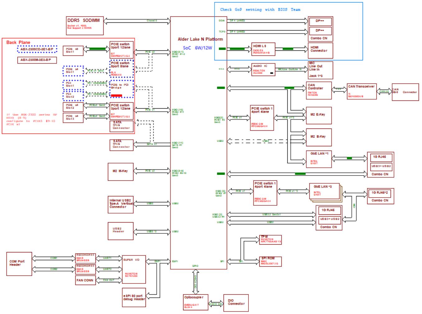
![Here is an accurate and concise description of the flowchart, listing the labeled blocks and their verbatim connections:\n\n**Central Component**\n*   **Alder Lake N Platform SoC 6W/12W**\n\n**Left Side Connections (Back Plane & I/O)**\n*   **DDR5 SODIMM** (Socket x1, 400, Not Support 2 RANK) connects via **Channel 0**.\n*   **Back Plane** block (containing **ABX-2300CD-3E1-BP** and **ABX-2300M-3E3-BP**) connects to:\n    *   **PCIe x8 Slot 1** via **PCIe x8** to **PCIe switch 1 port 12lane DT G4H090271G2**.\n    *   **PCIe switch 1 port 12lane** (green block) connects to the SoC via **PCIe x2** (labeled **HSG (0-1) PCE1 P1-2 Gen3**).\n    *   **PCIe switch 1 port 12lane DT G4H090271G2** connects to **PCIe switch 1 port 12lane** (green block) via a dashed **PCIe x4** line.\n    *   **PCIe x4 Slot 2** connects to **PCIe switch 1 port 12lane** (green block) via a dashed **PCIe x4** line.\n    *   **PCIe x4 Slot 3** connects to the bottom **PCIe switch 1 port 12lane DT G4H090271G2** via **PCIe x4 Gen3**.\n    *   **PCI Slot 1** and **PCI Slot 2** connect to **PCI to PCI Bridge** via dashed **PCI** lines.\n*   **SATA 7 Pin N Connector** connects to the SoC via **SATA 1** (labeled **HSG (11) SATA P1 Gen3**).\n*   **M2 M-Key** connects to the SoC via **PCle x4** (labeled **HSG (8-9) PCE2 P9-10 Gen3**).\n*   **Internal USB2 Type-A Vertical Connector** connects to the SoC via **USB2** (labeled **HSG (10) PC2 P11 Gen3**).\n*   **USB2 Header** connects to the SoC via **USB2_2**.\n*   **COM Port Header** connects via **COM1** to **RS232/232 RS DA6 SPANNER** to **UART1** to **SUPER I/O**.\n*   **SUPER I/O** connects to the SoC via **eSPI**.\n*   **NUMANION NCT5568 YX** connects to **SUPER I/O** via **eSPI** and connects to **UART2** to **RS232/232 RS DA6 SPANNER** to **COM2**.\n*   **FAN CONN** connects to **NUMANION NCT5568 YX** via **FAN OUT**.\n*   **eSPI 80 port debug Header** connects to **SUPER I/O** via **eSPI**.\n\n**Right Side Connections (Display, Audio, LAN, Storage)**\n*   **Check GoP setting with BIOS Team** (blue box).\n*   **DP++** connects via **DP 4 Lanes** (via **GGA**) to the SoC.\n*   **DP++** connects via **DP 4 Lanes** (via **TCP0**) to the SoC.\n*   **HDMI Connector** connects to the SoC via **HDMI LS** (via **GOG ES R2H02120 8**).\n*   **Combo CN** connects to the SoC via **HDMI LS** (via **GOG ES R2H02120 8**).\n*   **MIC Line Out Line In Jack 1*3** connects via **MIC Line Out/Line In** (via **REALTEK ALC888**) to **AUDIO IC** (**REALTEK ALC888**). The Audio IC connects to the SoC via **HDA** (via **PPA**).\n*   **CAN Controller** (**FINGER F0160M**) connects via **CAN** to **CAN Transceiver** (**TI TSC1006DU B**). The Transceiver connects to **CAN 35-9 Connector**.\n*   **M2 E-Key** and **M2 B-Key** connect via **PCle x1** to **PCle switch 1 4port 4lane** (**PERIC ON PTGCG204 6**). This switch connects to the SoC via **PCle x1** (labeled **HSG (5) PC2 P7 Gen3**).\n*   **GbE LAN *1** (**INTEL D1011**) connects via **PCle x1** to the first **PCle switch 1 4port 4lane**.\n    *   GbE LAN *1 connects to **10 RJ45** and **USB3+ USB2** / **Combo CN**.\n*   **GbE LAN *5** (**INTEL D1011**) connects via **PCle x1** to a second **PCle switch 1 4port 4lane** (**PERIC ON PTGCG204 6**). This switch connects to the SoC via **PCle x1** (labeled **HSG (5) PC2 P7 Gen3**).\n    *   GbE LAN *5 connects to **10 RJ46*2** / **Combo CN**, **1G RJ46*2**, and **USB3+ USB2** / **Combo CN**.\n*   **IPM** (**NUVOTON NCT5568 YX**) connects to the SoC via **SPI**. IPM connects to **SPI ROM** (**N25C1507 3 G**) via **SPI**.\n*   **Optocoupler EVERLIGHT SLM-4** connects to the SoC via **DIO IN**. The Optocoupler connects to **DIO Connector** via **DIO OUT**.](.mxc-3300-and-3340-50m-41057-1000-10/8e531c14639a2f8390dbf911c2d0303d7584c452ae1f3645479f3dbe57d3c4d7.jpg)

Figure 1: Functional block diagram

This page intentionally left blank.

# 4. Mechanical Layouts

# Connector Locations
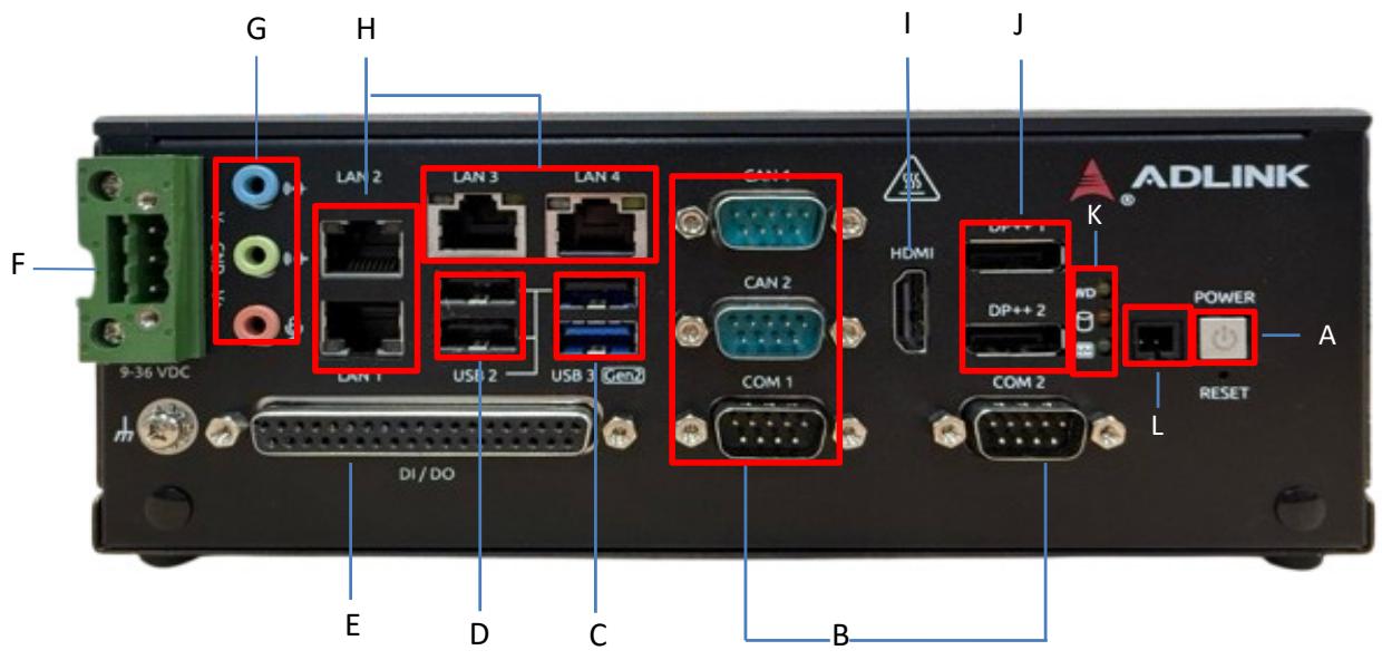
![G\nH\nI\nJ\nF\n9-36 VDC\nLAN 2 LAN 3 LAN 4\nCAN 1\nCAN 2\nCOM 1\nDI / DO\nE D C\nB\nHDMI\nDP++ 1\nAD\nK\nCOM 2\nPOWER\nA\nL\nRESET](.mxc-3300-and-3340-50m-41057-1000-10/d6b42f19c4c79fe454582280d0442a58548c29231d1e2f59ea0b8a1d17cf5ba2.jpg)

Table 1: Connector locations

<table><tr><td>A</td><td>Power Button</td><td>G</td><td>Audio</td></tr><tr><td>B</td><td>2x Isolation COM &amp; 2x CAN</td><td>H</td><td>4x Ethernet LAN</td></tr><tr><td>C</td><td>1x USB 3.2 Gen2 1xUSB 2.0</td><td>I</td><td>HDMI</td></tr><tr><td>D</td><td>2x USB 2.0</td><td>J</td><td>2x DP</td></tr><tr><td>E</td><td>Digital I/O</td><td>K</td><td>LED Indicators</td></tr><tr><td>F</td><td>DC input</td><td>L</td><td>External Power Button</td></tr></table>

# Mechanical Dimensions

# 4.2.1 MXC-3300 Mechanical Dimensions

![9-36 VDC\nLAN 2 LAN 3 LAN 4 CAN 1\nLAN 1 USB 2 USB 3 CAN 2 COM 1 COM 2\nDI/DO\nADLINK\nHDMI DP+1\nDP+2\nPOWER\nRESET\n79.70\n210](.mxc-3300-and-3340-50m-41057-1000-10/10631d9fbea08e902b5aef3400e752aa68a6423092ac0cf5e36fb311b18644e2.jpg)

Figure 2: MXC-3300 mechanical dimensions (Front view)

![Technical line drawing of a rectangular electronic device with mounting holes and a central component (no text or symbols)](.mxc-3300-and-3340-50m-41057-1000-10/caff170b41a4a05352f439b4f71d5bd4fb7fb29cb4d87ce7bddae3f5494b3b7a.jpg)

Figure 3: MXC-3300 mechanical dimensions (Rear view)

![Technical line drawing of a rectangular electronic component with horizontal stripes and a labeled 'Matrix' logo, dimensioned as 219.10 (no text or symbols beyond label)](.mxc-3300-and-3340-50m-41057-1000-10/00998abf814b4a080644f234f0f40727427dad2d2dcdaf55694880232919dda3.jpg)

Figure 4: MXC-3300 mechanical dimensions (Top view)

![Technical line drawing of a square mechanical component with mounting holes and mounting points (no text or symbols)](.mxc-3300-and-3340-50m-41057-1000-10/05b6af935c009718339760a77a36e97910d031d1f7719d28199ed242835787df.jpg)

Figure 5: MXC-3300 mechanical dimensions (Bottom view)

![Technical line drawing of a mechanical component with slots and mounting feet (no text or symbols)](.mxc-3300-and-3340-50m-41057-1000-10/2bdd1e21d1c8564adbe82abee0df4829fa67b7b28d5a8cf89e827694ebb255a3.jpg)

Figure 6: MXC-3300 mechanical dimensions (Side view)

# 4.2.2 MXC-3340 Mechanical Layout

![ADLINK\nLAN 2 LAN 3 LAN 4 CAN 1\nHDMI DP++1\nCAN 2\nCOM 1 COM 2 RESET\nDI/DO\n161.90](.mxc-3300-and-3340-50m-41057-1000-10/0faae9fe80faf43336ca17d4a2f6916f34dd4a29bfa88315aefa2f25c3a7d21c.jpg)

Figure 7: MXC-3340 mechanical dimensions (Front view)

![Simple diagram with circles and dots inside a rectangular frame (no text or symbols)](.mxc-3300-and-3340-50m-41057-1000-10/0de95b565a82a9ea1e4f7a1a974bac6e57be3b0e7ca659bcb934447ce37cef52.jpg)

Figure 8: MXC-3340 mechanical dimensions (Rear view)

![210\n219.10\nMatrix](.mxc-3300-and-3340-50m-41057-1000-10/5f248e1033faaf07bce37e2ee23381e23445a0f466b47d5c73f35d2cdca17937.jpg)

Figure 9: MXC-3340 mechanical dimensions (Top view)

![Pure technical line drawing of a rectangular panel with mounting holes and internal features (no text or symbols)](.mxc-3300-and-3340-50m-41057-1000-10/35bdd970ce7317be468f94445a52ab36f78bbe9f9bbc8db161b4bf5899d8410a.jpg)

Figure 10: MXC-3340 mechanical dimensions (Bottom view)

![Technical line drawing of a mechanical component with hexagonal holes and internal slots (no text or symbols)](.mxc-3300-and-3340-50m-41057-1000-10/74ddb36726a65bb618ff9edced2ca8dbd2551a9e122b8d30c9788f838e22bbf2.jpg)

Figure 11: MXC-3340 mechanical dimensions (Side view)

# 5. Quick Installation

This chapter discusses the installation of a hard disk drive and PCIe cards. In addition, it covers the connection and use of M.2 devices, as well as wall-mounting.

# Unpacking Checklist

Before unpacking, check the shipping carton for any damage. If the shipping carton and/or contents are damaged, inform your dealer immediately. Keep the shipping carton and packing materials for inspection. Obtain authorization from your dealer before returning any product to ADLINK. Ensure that the following items are included in the package:

1x 93-41057-\*\*\*\* MXC-3300/MXC-3340
• 2x 34-35509-0000-A0 (Wall mount Bracket)
• 1x 20-C1F0C-0030 (Terminal block)

# Installing SSD Storage

# 5.2.1 Installing MXC-3300 SSD

Loosen the screws on the SSD tray and pull it out to install the SATA SSD.

![Technical line drawings of a dual-chamber electronic device with internal cooling fins and mounting ports (no text or symbols)](.mxc-3300-and-3340-50m-41057-1000-10/0f41743b38af8e7420d5ddb48c5049370cc99b0af5228b90633e8a5db1783bc0.jpg)

# 5.2.2 Installing MXC-3340 SSD

1. Loosen the screws on the front case, then pull out the cover.
2. Remove the screws and take out the SSD tray.
3. Install the SATA SSD and secure it with screws.

![Technical line drawing of a mechanical or electronic device with ports and connectors (no text or symbols)](.mxc-3300-and-3340-50m-41057-1000-10/6522e78ce575662d0daf726fe54a3c530d7837c8c9feb30c034879d172bab692.jpg)

![Technical line drawing of an electronic device internal structure with no visible text or symbols](.mxc-3300-and-3340-50m-41057-1000-10/96cd1bc267011270738d39843ecb1755dbf7ed52f89e5e981455e92802cd040f.jpg)

# Installing PCIe Card

1. Loosen the screws on the front case, then pull off the cover.

![The image displays three technical line drawings of a computer tower chassis in an isometric perspective.\n\n**Top Left:** A view of the fully assembled computer case. The front panel features horizontal drive bays and a rear I/O panel with various ports. The text 'Advantage' is printed on the bottom right corner of the front faceplate.\n\n**Top Right:** The same chassis with the left side panel removed, revealing the internal components. Visible elements include the motherboard, a power supply unit, drive bays, and internal cabling. The removed side panel is shown floating to the right.\n\n**Bottom Left:** A close-up view of the internal motherboard area. This drawing highlights the motherboard layout, including expansion slots, heatsinks, RAM slots, and various connectors.](.mxc-3300-and-3340-50m-41057-1000-10/5390e6e348ed5f5cf1176d6880dcb076e83fb0962c5be1ac2d24dfd7df4d7dd4.jpg)

2. Remove the PCIe bracket, then install the PCIe card.

![The image displays three technical line drawings illustrating different configurations of a rugged computer chassis or embedded system.\n\n*   **Top Left:** Shows an exploded view where a side mounting bracket is detached and floating to the left, aligned with the chassis by dashed lines. The internal motherboard, expansion slots, and cooling fins are visible. The text **'ADVANTECH'** is printed near the rear I/O ports, accompanied by the number sequence **'45671891'**.\n*   **Top Right:** Shows the chassis with the side panel assembled. The internal motherboard and components are visible through the opening. The text **'ADVANTECH'** is visible near the rear ports.\n*   **Bottom Left:** Shows the chassis with a large, rectangular external module (resembling a drive bay) attached to the front/side. The text **'ADVANTECH'** is visible near the rear ports.](.mxc-3300-and-3340-50m-41057-1000-10/db037b1394198e1dfc6734a9073a572eb2ca07a2b441018a39dc0aead1ff6411.jpg)

# Installing M.2 Module

5.4.1 Installing MXC-3300 M.2 Module

1. Remove the 6 screws from the rear panel and the case.
2. Install the M.2 module in the location specified in Section 1.6.

![Technical line drawing of an electronic device chassis with labeled components (no text or symbols present)](.mxc-3300-and-3340-50m-41057-1000-10/175b065a4d6ec1c0c1c833cbe92eee55d291806838aa2396eed7f8acea4904ae.jpg)

![Technical line drawing of an electronic device chassis with ports, connectors, and internal components (no text or labels)](.mxc-3300-and-3340-50m-41057-1000-10/818982d2842c6c615dfa0f6dc43c2809167ce28c6323d63863ad26f30a2771ac.jpg)

# 5.4.2 Installing MXC-3340 M.2 Module

1. Loosen the screws on the front case, then pull off the cover.
2. Install the M.2 module in the location specified in Section 6.2.

![Technical line drawing of an internal computer chassis showing external and internal components (no text or labels)](.mxc-3300-and-3340-50m-41057-1000-10/9719bf5284cbcf14c1ff019be0ae4c62e8ba79ee52c5859565d5f7505a1a7f8e.jpg)

3. Install the M.2 module in the location specified in Section 6.2.

![Technical line drawing of an internal computer chassis with visible circuit boards and connectors (no text or labels)](.mxc-3300-and-3340-50m-41057-1000-10/aabb1c38c102575b6bee2edb76ee307ea6dd1421809233f2ced52be2594b340f.jpg)

![The image features a standard yellow triangular warning sign with a black border and a black exclamation point in the center. Below the triangle, the text 'CAUTION:' appears in black capital letters.](.mxc-3300-and-3340-50m-41057-1000-10/d3ce75ab6e60ee3b7556e70c256fcc3fa59f9c8651e8440e2788d8459dbb8039.jpg)

Be careful not to remove or damage any wires while installing the module.

Veillez à ne pas retirer ou endommager les fils lors de l'installation du module

# Installing Wall-Mounted Brackets

# 5.5.1 Installing Wall-Mounted MXC-3300 Brackets

1. Remove the 6 screws from the rear panel.

![Technical line drawing of a computer chassis with ports and connectors (no text or symbols)](.mxc-3300-and-3340-50m-41057-1000-10/1dd2cf435ede853e96e3f8b2374627cff7c1e4f7128a3eae49870809a730912c.jpg)

2. Install the wall-mounted brackets and secure it with screws.

![Technical diagram of an electronic device with labeled ports and connectors, showing internal components and mounting brackets.](.mxc-3300-and-3340-50m-41057-1000-10/9a2a680bc884152fc42612e86d949f8175995cef47e2f081cfd1178975e5f912.jpg)

# 5.5.2 Installing Wall-Mounted MXC-3340 Brackets

1. Remove the 6 screws from the rear panel.

![Technical line drawing of a server rack unit with mounting hardware and ventilation slots (no text or symbols)](.mxc-3300-and-3340-50m-41057-1000-10/c719a852d7cd75aeed37d7ea38930e0e83dca530e075cccc146ad76a158faac5.jpg)

2. Install the wall-mounted brackets and secure it with screws.

![Technical line drawing of an electronic device chassis with mounting brackets and connectors (no text or symbols)](.mxc-3300-and-3340-50m-41057-1000-10/eb17577053d3d21230945389c80747b64db158ac5e57f510935a5ecfdd9264cb.jpg)

# 6. Connectors and Jumpers

# 6.1 Front Panel I/O Connectors

# 6.1.1 Power Button and LEDs

The power button is a non-latched push button with a blue LED indicator. System is turned on when button is pressed, and the power LED lit. If the system hangs, pressing the button for 5 seconds powers down the system.

<table><tr><td>System status</td><td>Power LED</td></tr><tr><td>System turn on</td><td>Light ON</td></tr><tr><td>Suspend (S3)</td><td>Blinking</td></tr><tr><td>Hybernation (S4)</td><td>Blinking</td></tr><tr><td>Power OFF (S5)</td><td>Light OFF</td></tr></table>

# 6.1.2 LED Status Indicators

There are three LEDs on the front panel, apart from the power LED, indicating the following operations.

<table><tr><td>LED Indication</td><td>Location</td><td>Color</td><td>Description</td></tr><tr><td>Watchdog Timer (WDT)</td><td>LED1</td><td>Yellow</td><td>It indicates the watchdog timer status. When watchdog timer starts, the LED flashes. When the timer is expired, the LED remains lit.</td></tr><tr><td>Hard Disk Drive (HDD)</td><td>LED2</td><td>Orange</td><td>When blinking, it indicates the SATA HDD &amp; SSD are active.</td></tr><tr><td>Diagnostics (DG)</td><td>LED3</td><td>Grenn</td><td>If the light is continuous, it indicates no physical storage is connected.</td></tr></table>

# 6.1.3 Reset Button

The reset button executes hard reset for the MXC-3300 & MXC-3340.

# 6.1.4 DisplayPort Connector

A single DisplayPort connector supporting DP 1.4 standard specification facilitates connectivity to VGA, DVI, HDMI, and DisplayPort monitors using adapter cables, supporting resolutions up to 3840 x 2160 at 60Hz.

<table><tr><td>Pin</td><td>Signal</td><td>Pin</td><td>Signal</td></tr><tr><td>1</td><td>ML_Lane0_P</td><td>11</td><td>GND</td></tr><tr><td>2</td><td>GND</td><td>12</td><td>ML_Lane3_N</td></tr><tr><td>3</td><td>ML_Lane0_N</td><td>13</td><td>Config1</td></tr><tr><td>4</td><td>ML_Lane1_P</td><td>14</td><td>Config2</td></tr><tr><td>5</td><td>GND</td><td>15</td><td>Aux_P</td></tr><tr><td>6</td><td>ML_Lane1_N</td><td>16</td><td>GND</td></tr><tr><td>7</td><td>ML_Lane2_P</td><td>17</td><td>Aux_N</td></tr><tr><td>8</td><td>GND</td><td>18</td><td>Hot Plug</td></tr><tr><td>9</td><td>ML_Lane2_N</td><td>19</td><td>Return</td></tr><tr><td>10</td><td>ML_Lane3_P</td><td>20</td><td>DP_PWR_+3.3V</td></tr></table>

![2\n20\n1\n19](.mxc-3300-and-3340-50m-41057-1000-10/173133692654bdca7a45470b343a11366ca01637c7ac8af9dc59b79e8f662d3e.jpg)

# 6.1.5 Gigabit Ethernet Ports

Four Gigabit Ethernet ports on the front panel support the Inteli210IT GbE controller, which provides:

IEEE 802.3az Energy Efficient Ethernet
IEEE 1588/802.1AS precision time synchronization
IEEE 802.3av traffic shaper
Interrupt moderation, VLAN support, IP checksum offload
• PCIe OBFF (Optimized Buffer Flush/Fill) for improved system power management
• Four transmit and four receive queues
RSS and MSI-X to lower CPU utilization in multi-core systems
ECC - error correcting memory in packet buffers
Wake-On-LAN
• NC-SI for greater bandwidth pass-through
• Preboot eXecution Environment (PXE) flash interface sup- port
• Jumbo frame support

<table><tr><td>LED</td><td>LED Color</td><td>Status</td><td>Description</td></tr><tr><td rowspan="3">Active/Link</td><td rowspan="3">Yellow</td><td>OFF</td><td>The Ethernet port is disconnected</td></tr><tr><td>ON</td><td>The Ethernet port is connected with noactivity</td></tr><tr><td>Flashing</td><td>The Ethernet port is connected and active</td></tr><tr><td rowspan="3">Speed</td><td rowspan="3">Green/Orange</td><td>OFF</td><td>10 Mbps</td></tr><tr><td>Green</td><td>100Mbps</td></tr><tr><td>Yellow</td><td>1G bps</td></tr></table>

# 6.1.6 USB

There are 3x USB 2.0 ports (0.5A current/port) and 1x USB 3.0 port (1A current) on the front panel. All ports have over current protection.

# 6.1.7 DB-9P COM Port Connector

Through a D-sub 9-pin connector, COM1 or COM2 supports RS-232/RS-422/RS-485mode by BIOS setting.

<table><tr><td rowspan="2">Pin</td><td colspan="3">Signal</td></tr><tr><td>RS-232</td><td>RS-422</td><td>RS-485</td></tr><tr><td>1</td><td>DCD#</td><td>TXD422-</td><td>485-</td></tr><tr><td>2</td><td>RXD</td><td>TXD422+</td><td>485+</td></tr><tr><td>3</td><td>TXD</td><td>RXD422+</td><td>N/C</td></tr><tr><td>4</td><td>DTR#</td><td>RXD422-</td><td>N/C</td></tr><tr><td>5</td><td>GND</td><td>N/C</td><td>N/C</td></tr><tr><td>6</td><td>DSR#</td><td>N/C</td><td>N/C</td></tr><tr><td>7</td><td>RTS#</td><td>N/C</td><td>N/C</td></tr><tr><td>8</td><td>CTS#</td><td>N/C</td><td>N/C</td></tr><tr><td>9</td><td>RI#</td><td>N/C</td><td>N/C</td></tr></table>

![1\n5\n6\n9](.mxc-3300-and-3340-50m-41057-1000-10/089279b7accbd24fd0d14b21a213ab848f5bae00677a4021d19cc7b4c5a38dda.jpg)

# 6.1.8 DB-9P CAN Port Connector

Through a D-sub 9-pin connector, CAN1 or CAN2 supports CAN Bus2.0.

<table><tr><td>Pin</td><td>Signals</td><td>Pin</td><td>Signals</td></tr><tr><td>1</td><td>NC</td><td>6</td><td>NC</td></tr><tr><td>2</td><td>CAN_L</td><td>7</td><td>CAN_H</td></tr><tr><td>3</td><td>NC</td><td>8</td><td>NC</td></tr><tr><td>4</td><td>NC</td><td>9</td><td>NC</td></tr><tr><td>5</td><td>NC</td><td></td><td></td></tr></table>

# 6.1.9 Digital I/O Connectors

There are 8 DI and 8 DO on the wafer connector. The DO signal has a PH \*P\_+5V\_S0 on the motherboard (MB) side, with an output current of 8mA. The DI signal has a 100kΩ pull-down resistor on the MB side.

Connector info:

Manufacturer: HIROSE

MFG P/N: DF13E-40DP-1.25V (52)

ADLINK P/N: 61-61000-2200

# 8-CH Isolated DI

Logic high: 5 to 24 V

Logic low: 0 to 1.5 V

Input resistance: 8.2K @ 0.75W

Isolation type: photocoupler, 1.5KV

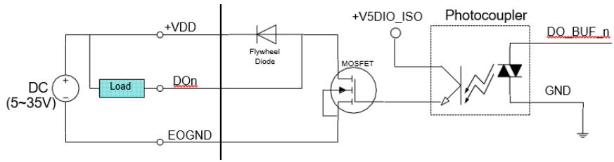
# 8-CH Isolated DO

Output Type: MOSFET transistor

Sink current up to 100 mA (sustained loading) or 250 mA

(Peak loading) on each isolated output channel

Supply voltage: 5 to 35 V DC

# Isolated 5V DC Power Source for DO

Supply voltage: 5 ± 0.5V DC

Supply current: 180 mA (maximum)

Isolation type: DC-to-DC transformer, 1.5KV

<table><tr><td>Signals</td><td>DB37(F)</td><td>Signals</td><td>DB37(F)</td></tr><tr><td>DI0_H</td><td>1</td><td>V5DIO_CN_ISO</td><td>18</td></tr><tr><td>DI0_L</td><td>2</td><td>GND</td><td>19</td></tr><tr><td>DI1_H</td><td>3</td><td>DO0</td><td>20</td></tr><tr><td>DI1_L</td><td>4</td><td>DO1</td><td>21</td></tr><tr><td>DI2_H</td><td>5</td><td>DO2</td><td>22</td></tr><tr><td>DI2_L</td><td>6</td><td>DO3</td><td>23</td></tr><tr><td>DI3_H</td><td>7</td><td>DO4</td><td>24</td></tr><tr><td>DI3_L</td><td>8</td><td>DO5</td><td>25</td></tr><tr><td>DI4_H</td><td>9</td><td>DO6</td><td>26</td></tr><tr><td>DI4_L</td><td>10</td><td>DO7</td><td>27</td></tr><tr><td>DI5_H</td><td>11</td><td>GND</td><td>28</td></tr><tr><td>DI5_L</td><td>12</td><td>GND</td><td>29</td></tr><tr><td>DI6_H</td><td>13</td><td>GND</td><td>30</td></tr><tr><td>DI6_L</td><td>14</td><td>GND</td><td>31</td></tr><tr><td>DI7_H</td><td>15</td><td>VDD</td><td>35</td></tr><tr><td>DI7_L</td><td>16</td><td>V5DIO_CN_ISO</td><td>36</td></tr><tr><td>VDD</td><td>17</td><td>GND</td><td>37</td></tr></table>

<table><tr><td rowspan="4">DI</td><td>DIn_H</td><td>High input of isolated differential DI channel (n=0 to 7)</td></tr><tr><td>DIn_L</td><td>Low input of isolated differential DI channel (n=0 to 7)</td></tr><tr><td>DIn</td><td>Input of isolated DI channel (n=8 to 15)</td></tr><tr><td>ISO_COM</td><td>Common ground of isolated DI channel 8 to 15</td></tr><tr><td rowspan="4">DO</td><td>DOn</td><td>Output of isolated DO channel (n=0 to 15)</td></tr><tr><td>EOGND</td><td>Ground return path of isolated DO channel 0 to 15 and +V5DIO_CN_ISO</td></tr><tr><td>+VDD</td><td>Power input signal for flywheel diode of isolated DO channel 0 to 15</td></tr><tr><td>+V5DIO_CN_ISO</td><td>Isolated 5V DC power, maximum output 180mA</td></tr></table>

# 6.1.10 Isolated Digital Input Circuits

Input accepts voltages from 5V to 24V, with input resistors of 2.4 kΩ, and connections between external signals as shown.
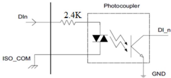
![DIn\n2.4K\nPhotocoupler\nDI_n\nISO_COM\nGND](.mxc-3300-and-3340-50m-41057-1000-10/94b33fc293e906597a773fdf169c45447c1133ac156e01f99c6951e37213d42b.jpg)

# 6.1.11 Isolated Digital Output Circuits

Each isolated digital output channel uses a MOSFET transistor, capable of driving a peak current of up to 250mA (sustained current up to 100mA), with voltage ranges from 5V to 35V.

The VDD pin is connected in series with a flyback diode to protect the driver during inductive loading, such as with a relay, motor, or solenoid. In this configuration, the VDD must be connected to external power to form a flyback current loop.

# Isolated Digital Output Circuits
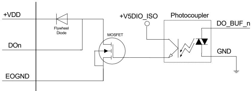
![+VDD\nFlywheel\nDiode\n+V5DIO_ISO\nPhotocoupler\nDO_BUF_n\nDOn\nMOSFET\nGND\nEOGND](.mxc-3300-and-3340-50m-41057-1000-10/40c42f145101d309ccb5e01b3210728b60f6c43338167554f32e4210e71d4acd.jpg)

# Isolated Digital Output Circuits

![DC\n(5~35V)\n+VDD\nLoad\nDOn\nEOGND\nFlywheel\nDiode\n+V5DIO_ISO\nMOSFET\nPhotocoupler\nDO_BUF_n\nGND](.mxc-3300-and-3340-50m-41057-1000-10/01d4651e55e55e841638f229cd865e5cb34d3dfc4b9d459d47376deaee4911c0.jpg)

# 6.1.12 Audio Jacks

The MXC-3300 & MXC-3340 implement Intel high-definition audio on a Realtek ALC888S chip. The HD audio supports up to 24-bit, 192 kHz sample rate for high-quality headphone/line out and microphone input. Audio jack access is on the front panel. The pink jack provides microphone input, and the green jack is for line out.

<table><tr><td>Color</td><td>Signal</td></tr><tr><td>Blue</td><td>Line in</td></tr><tr><td>Green</td><td>Line out</td></tr><tr><td>Pink</td><td>Mic In</td></tr></table>

![Three ring-shaped objects are stacked vertically against a black background. The top ring is light blue, the middle ring is lime green, and the bottom ring is peach. To the right of the blue and green rings are double-headed horizontal arrows, while a microphone icon appears to the right of the peach ring.](.mxc-3300-and-3340-50m-41057-1000-10/883e9077ef806dc6d3c2815963c8ab95bc6d669cf1e3994168665eb1af641e3d.jpg)

# 6.1.13 DC Power Connector

The DC power supply connector of the MXC-3300 & MXC-3340 is located on the front panel. The power supply connector consists of three pins: V+, chassis ground, and V-, from right to left, respectively. The V+ and V- pins provide DC power input, and the chassis ground pin allows the connection of the chassis to ground for better EMC compatibility. The DC power input for the MXC-3300 & MXC-3340 supports a voltage input range from 9V DC to 36V DC.

![Close-up of a green electronic component with internal slots and mounting holes (no readable text or symbols)](.mxc-3300-and-3340-50m-41057-1000-10/f7ca0a92b681a11b0cacd2f521e9a432876e844dfc5d78e1ba974639e99e1110.jpg)

# 6.1.14 PCI Express Slots

The 3x PCIe slots on the backplane board, based on the PCI Express switch, can support standard PCIe Gen 1/2 cards, with link speeds of up to 1 GB/s.

# 6.2 Internal I/O Connectors

MXC3300 and MXC-3340 MB

![M.2 M\nDDR\nM.2 E\nM.2 B](.mxc-3300-and-3340-50m-41057-1000-10/3f3bb285b3985e17a857e5926a75c5ee1be60431747b006860fa77360b37fb11.jpg)

MXC-3340 series BP

![PCle x4\nPCle x8](.mxc-3300-and-3340-50m-41057-1000-10/03b46ab0737700f107d5c8f3925a5deecdc2b5745b3e6b024b7f1dc65c9f547f.jpg)

This page intentionally left blank.

# 7. BIOS Settings

# 7.1 Main

Contains basic system information for the MXC-3300.

Changing BIOS settings may lead to incorrect controller behavior and possible inability to boot.

<table><tr><td colspan="2">Main Advanced Chipset Security Boot Save &amp; Exit</td></tr><tr><td>BIOS Information
BIOS Vendor American Megatrends Inc.
BIOS Version 1.01.10
Build Date 10/15/2024
MRC Version 0.0.4.74
GOP Version 21.0.1063
ME FW Version 16.50.10.1351</td><td>Set the Date. Use Tab to switch between Date elements.
Default Ranges:
Year: 1998-9999
Months: 1-12
Days: Dependent on month
Range of Years may vary.</td></tr><tr><td>System Information
Project Name MXC-3340
CPU Board Version A2
CPU Brand String Intel(R) N97
CPU Frequency 2.00GHz
Total Memory 8192 MB (DDR5)
Memory Frequency 4800 MHz
PCH SKU N Premium SKU</td><td rowspan="3">+: Select Screen
↑↓: Select Item
Enter: Select
+/-: Change Opt.
F1: General Help
F8: Previous Values
F9: Optimized Defaults
F10: Save &amp; Exit
ESC: Exit</td></tr><tr><td>System Date [Thu 11/28/2024]
System Time [18:46:06]</td></tr><tr><td>Access Level Administrator</td></tr><tr><td colspan="2">Version 2.22.1292 Copyright (C) 2024 AMI</td></tr></table>

# BIOS Information

Shows current system BIOS code version and BIOS version.

# System Time/System Date

Allows adjustment of system time and date, as follows.

1. Highlight System Time or System Date using the up and down &lt;Arrow&gt; keys
2. Enter new values using the keyboard and select &lt;Enter&gt;
3. Select &lt; Tab &gt; to move between fields.

# 7.2 Advanced

<table><tr><td colspan="2">Aptio Setup - AMI
Main Advanced Chipset Security Boot Save &amp; Exit</td></tr><tr><td>CPU Configuration
Power Management
Hardware Monitor
BIOS Watchdog Timer
Onboard Device
Serial Console Redirection
TPM 2.0 Configuration
NVMe Configuration
Network Stack Configuration
Intel(R) I210 Gigabit Network Connection - 00:30:64:77:E5:80
Intel(R) I210 Gigabit Network Connection - 00:30:64:77:E5:81
Intel(R) I210 Gigabit Network Connection - 00:30:64:77:E5:7C
Intel(R) I210 Gigabit Network Connection - 00:30:64:77:E5:7D</td><td>CPU Configuration</td></tr><tr><td></td><td>+: Select Screen
↑↓: Select Item
Enter: Select
+/-: Change Opt.
F1: General Help
F8: Previous Values
F9: Optimized Defaults
F10: Save &amp; Exit
ESC: Exit</td></tr><tr><td colspan="2">Version 2.22.1292 Copyright (C) 2024 AMI</td></tr></table>

![The image displays a yellow triangular warning sign with a black border. Centered within the triangle is a large black exclamation point. The sign is positioned on a white background that shows faint grid lines.](.mxc-3300-and-3340-50m-41057-1000-10/a2fe984a81bf044948d598008f29ed137288a483fd8da3ce6a6f8d6d749296cf.jpg)
CAUTION:

Setting incorrect or conflicting values in Advanced BIOS Setup may cause system malfunction. Configurer des valeurs incorrectes ou conflictuelles dans le menu Advanced BIOS Setup peut entraîner un dysfonctionnement du système.

# 7.2.1 Advanced > CPU Configuration

<table><tr><td colspan="2">CPU Configuration</td><td rowspan="10">Number of E-cores to enable in each processor package. Note: Number of Cores and E-cores are looked at together. When both are {0,0}, Pcode will enable all cores.</td></tr><tr><td>ID</td><td>0xB06E0</td></tr><tr><td>Brand String</td><td>Intel(R) N97</td></tr><tr><td>Microcode Revision</td><td>15</td></tr><tr><td>L1 Data Cache</td><td>32 KB x 4</td></tr><tr><td>L1 Instruction Cache</td><td>64 KB x 4</td></tr><tr><td>L2 Cache</td><td>2048 KB</td></tr><tr><td>L3 Cache</td><td>6 MB</td></tr><tr><td>VMX</td><td>Supported</td></tr><tr><td>SMX/TXT</td><td>Not Supported</td></tr><tr><td>Active Efficient-cores</td><td>[All]</td><td rowspan="8">+: Select Screen
↑↓: Select Item
Enter: Select
+/-: Change Opt.
F1: General Help
F8: Previous Values
F9: Optimized Defaults
F10: Save &amp; Exit
ESC: Exit</td></tr><tr><td>Intel(R) SpeedStep(tm)</td><td>[Enabled]</td></tr><tr><td>Turbo Mode</td><td>[Disabled]</td></tr><tr><td>Intel(R) Speed Shift Technology</td><td>[Enabled]</td></tr><tr><td>Intel (VMX) Virtualization</td><td>[Enabled]</td></tr><tr><td>Technology</td><td></td></tr><tr><td>VT-d</td><td>[Enabled]</td></tr><tr><td>C states</td><td>[Disabled]</td></tr></table>

# Active Efficient-cores

Number of cores to enable in each processor package.

[All (Default) / 3 / 2 / 1]

# Intel SpeedStep

Enable/Disable Intel SpeedStep.

[Disabled / Enabled (Default)]

# Turbo Mode

Enable/Disable processor Turbo Mode (requires EMTTM to be enabled too). [Disabled (Default) / Enabled]

# Intel(R) Speed Shift Technology

Enable/Disable Intel(R) Speed Shift Technology support.

Enabling will expose the CPPC v2 interface to allow for hardware-controlled P-states.

[Disabled / Enabled (Default)]

# Intel (VMX) Virtualization Technology

When enabled, a VMM can utilize the additional hardware capabilities provided by Vanderpool Technology.

[Disabled / Enabled (Default)]

# VT-d

Check to enable VT-d function on MCH.

[Disabled / Enabled (Default)]

# C states

Enable/Disable CPU Power Management.

Allows CPU to go to C states when it's not 100% utilized.

[Disabled (Default) / Enabled]

# 7.2.2 Advanced > Power Management

<table><tr><td colspan="2">Advanced Aptio Setup - AMI</td></tr><tr><td>Power Management
Enable Hibernation [Enabled]
ACPI Sleep State [S3 (Suspend to RAM)]
State After G3 [S0 State]</td><td>Enables or Disables System ability to Hibernate (OS/S4 Sleep State). This option may not be effective with some operating systems.</td></tr><tr><td></td><td>+: Select Screen
↑↓: Select Item
Enter: Select
+/-: Change Opt.
F1: General Help
F8: Previous Values
F9: Optimized Defaults
F10: Save &amp; Exit
ESC: Exit</td></tr><tr><td colspan="2">Version 2.22.1292 Copyright (C) 2024 AMI</td></tr></table>

# Enable Hibernation

Enables or Disables System ability to Hibernate (OS/S4 Sleep State).

This option may not be effective with some operating systems.

[Disabled / Enabled (Default)]

# ACPI Sleep State

Select the highest ACPI sleep state the system will enter when the SUSPEND button is pressed.

[Suspend Disabled / S3 (Suspend to RAM) (Default)]

# State After G3

Specify what state to go to when power is re-applied after a power failure (G3 state).

[S0 State (Default) / S5 State / Last State]

# 7.2.3 Advanced> Hardware Monitor

![Advanced\nAptio Setup - AMI\nHardware Monitor\nBoard Temperature 1 : +36 °\nBoard Temperature 2 : +39 °\nCPU-Vcore : +0.824 V\nV5.00 : +4.967 V\nV3.30 (VSB) : +3.328 V\nVBAT : +3.008 V\n+: Select Screen\n↑↓: Select Item\nEnter: Select\n+/-: Change Opt.\nF1: General Help\nF8: Previous Values\nF9: Optimized Defaults\nF10: Save & Exit\nESC: Exit\nVersion 2.22.1292 Copyright (C) 2024 AMI](.mxc-3300-and-3340-50m-41057-1000-10/e73aca21cdbcc1be9a7133db2d4fd65abdb79eeeb708d91521e995c9fea2f80e.jpg)

# 7.2.4 Advanced > BIOS Watchdog Timer

![Aptio Setup - AMI\nAdvanced\nBIOS Watchdog Timer\nBIOS POST Watchdog (Disabled)\n1. Disable: Disable WatchDog\nTimer; 2. Second Mode: Enable\nWatchdog Timer in second mode;\n3. Minute Mode: Enable\nWatchdog Timer in minute mode.\n+: Select Screen\n↑↓: Select Item\nEnter: Select\n+/-: Change Opt.\nF1: General Help\nF8: Previous Values\nF9: Optimized Defaults\nF10: Save & Exit\nESC: Exit\nVersion 2.22.1292 Copyright (C) 2024 AMI](.mxc-3300-and-3340-50m-41057-1000-10/47eca0400908d3b74affd9ee5bc78bf3a02ecdfc50c4c6dc2f0c283575d3d976.jpg)

# BIOS POST Watchdog

Disabled: Disable the watchdog timer

Second Mode: Enable watchdog timer in second mode

Minute Mode: Enable watchdog Timer in minute mode.

[Disabled (Default) / Second Mode / Minute Mode]

# 7.2.5 Advanced > Onboard Device

![Optio Setup - AMI\nAdvanced\nOnboard Device\n► Serial Port 1 Configuration\nCOM1 Mode Control (RS232)\n► Serial Port 2 Configuration\nCOM2 Mode Control (RS232)\nCOM1 TX termination (Disable)\nCOM1 RX termination (Disable)\nCOM2 TX termination (Disable)\nCOM2 RX termination (Disable)\nSet Parameters of Serial Port 1 (COMA)\n+: Select Screen\n↑↓: Select Item\nEnter: Select\n+/-: Change Opt.\nF1: General Help\nF8: Previous Values\nF9: Optimized Defaults\nF10: Save & Exit\nESC: Exit\nVersion 2.22.1292 Copyright (C) 2024 AMI](.mxc-3300-and-3340-50m-41057-1000-10/2a1c1b2a497289588c266e573a714bc884f275b628eb5811e82bdc92a14f6030.jpg)

# Serial Port 1/2 Configuration

Set Parameters of Serial Port 1/2 (COMA/COMB).

Serial Port

Enable or Disable Serial Port (COM).

[Disabled / Enabled (Default)]

Change Settings

Select an optimal setting for Super IO Device.

```javascript
COM1: [Auto (Default)/ IO=3F8h; IRQ=4; / IO=3F8h; IRQ=3,4,5,6,7,9,10,11,12; / IO=2F8h; IRQ=3,4,5,6,7,9,10,11,12; / IO=3E8h; IRQ=3,4,5,6,7,9,10,11,12; / IO=2E8h; IRQ=3,4,5,6,7,9,10,11,12;]
```

```javascript
COM2: [Auto (Default)/ IO=2F8h; IRQ=3; / IO=3F8h; IRQ=3,4,5,6,7,9,10,11,12; / IO=2F8h; IRQ=3,4,5,6,7,9,10,11,12; / IO=3E8h; IRQ=3,4,5,6,7,9,10,11,12; / IO=2E8h; IRQ=3,4,5,6,7,9,10,11,12;]
```

# COM 1/2 Mode Control

Select COM1/COM2 mode. RS232, RS422, RS485.

[RS232 (Default) / RS422 / RS485]

# COM 1/2 TX/RX Termination

COM1/COM2 TX/RX termination Enable/Disable.

[Enable / Disable (Default)]

# 7.2.6 Advanced > Serial Console Redirection

![Aptio Setup - AMI\nAdvanced\nCOM1\nConsole Redirection (Disabled)\n► Console Redirection Settings\nCOM2\nConsole Redirection (Disabled)\n► Console Redirection Settings\nConsole Redirection Enable or\nDisable.\n+: Select Screen\n↑↓: Select Item\nEnter: Select\n+/-: Change Opt.\nF1: General Help\nF8: Previous Values\nF9: Optimized Defaults\nF10: Save & Exit\nESC: Exit\nVersion 2.22.1292 Copyright (C) 2024 AMI](.mxc-3300-and-3340-50m-41057-1000-10/150714d8d0762375c351281471fa586b2c05eed436405be2250726778951968c.jpg)

# COM1/ COM2 Console Redirection

Enables/disables Console Redirection of COM1/ COM2.

[Disabled (Default)/ Enabled] When Enabled:

Console Redirection Settings

# Terminal Type

Selects the transmission protocol for the remote terminal console. [VT100 / VT100Plus / VT-UTF8 / ANSI (Default)] VT100

ASCII char set VT100Plus

Extends VT100 to support color, function keys, etc. VT-UTF8

Uses UTF8 encoding to map unicode chars onto 1 or more bytes

# ANSI

Extended ASCII char set

# Bits per second

Selects serial port transmission speed, which must be matched on the other side. Long or noisy lines may require lower speeds.

[9600/ 19200 / 38400 / 57600/ 115200 (Default)]

Data Bits Data bit count [7/ 8 (Default)] Parity

A parity bit can be sent with the data bits to detect some transmis- sion errors.

[None (Default) / Even / Odd / Mark / Space] Even

Parity bit is 0 if 1 count in the data bits is even. Odd

Parity bit is 0 if 1 count in the data bits is odd. Mark

Parity bit is always 1. Space

Parity bit is always 0.

Mark and Space Parity do not allow for error detection. They can be used as an additional data bit.

# Stop Bits

Stop bits indicate the end of a serial data packet. (A start bit indicates the beginning). The standard setting is 1 stop bit. Communication with slow devices may require more than 1 stop bit.

[1 (Default)/ 2]

# Flow Control

Flow control can prevent data loss from buffer overflow. [None (Default)/ Hardware RTS/ CTS]

VT-UTF8 Combo Key Support

Enable VT-UTF8 Combination Key Support for ANSI/VT100 terminals.

[Disabled / Enabled (Default)]

# Recorder Mode

When enabled only text will be sent, to capture Terminal data.

[Disabled (Default)/ Enabled]

# Resolution 100x31

Enables/disables extended terminal resolution.

[Disabled (Default)/ Enabled]

# Putty KeyPad

Selects Function Key and KeyPad on Putty.

[VT100 (Default) / LINUX / XTERMR6 / SCO / ESCN / VT400]

# 7.2.7 Advanced > TPM 2.0 Configuration

<table><tr><td colspan="2">Aptio Setup - AMI</td></tr><tr><td>TPM 2.0 Device Found
Firmware Version: 7.2
Vendor: NTC
Security Device Support [Enable]
Active PCR banks SHA256
Available PCR banks SHA256,SHA384
SHA256 PCR Bank [Enabled]
SHA384 PCR Bank [Disabled]
Pending operation [None]
Platform Hierarchy [Enabled]
Storage Hierarchy [Enabled]
Endorsement Hierarchy [Enabled]
Physical Presence Spec Version [1.3]
TPM 2.0 InterfaceType [TIS]
Device Select [Auto]</td><td>Enables or Disables BIOS support for security device.
O.S. will not show Security Device. TCG EFI protocol and INT1A interface will not be available.</td></tr><tr><td></td><td>+: Select Screen
↑↓: Select Item
Enter: Select
+/-: Change Opt.
F1: General Help
F8: Previous Values
F9: Optimized Defaults
F10: Save &amp; Exit
ESC: Exit</td></tr><tr><td colspan="2">Version 2.22.1292 Copyright (C) 2024 AMI</td></tr></table>

# Security Device Support

Enable/Disable Security Device.

Note: Your Computer will reboot during restart in order to change State of the Device.

[Enable (Default) / Disable]

# SHA256 PCR Bank

Enable or Disable SHA256 PCR Bank.

[Enable (Default) / Disable]

# SHA512 PCR Bank

Enable or Disable SHA512 PCR Bank.

[Enable / Disable (Default)]

# Pending Operation

Enable or Disable Pending operation.

[None (Default) / TPM Clear]

# Platform Hierarchy

Enable or Disable Platform Hierarchy.

[Disable / Enable (Default)]

# Storage Hierarchy

Enable or Disable Storage Hierarchy.

[Disable / Enable (Default)]

# Endorsement Hierarchy

Enable or Disable Endorsement Hierarchy.

[Disable / Enable (Default)]

# Physical Presence Spec Version

Select to tell O.S. to support PPI Spec Version 1.2 or 1.3.

Note: some HCK tests might not support 1.3.

[1.2 / 1.3 (Default)]

# Device Select

TPM 1.2 will restrict support to TPM 1.2 devices, TPM 2.0 will restrict support to TPM 2.0 devices, Auto will support both with the default set to TPM 2.0 devices if not found, TPM 1.2 devices will be enumerated.

[TPM 1.2 / TPM 2.0 / Auto (Default)]

# 7.2.8 Advanced > NVMe Configuration

![Aptio Setup - AMI\nAdvanced\nNVMe Configuration\n► ASDEM8EDE-2566T0\n+: Select Screen\n↑↓: Select Item\nEnter: Select\n+/-: Change Opt.\nF1: General Help\nF8: Previous Values\nF9: Optimized Defaults\nF10: Save & Exit\nESC: Exit\nVersion 2.22.1292 Copyright (C) 2024 AMI](.mxc-3300-and-3340-50m-41057-1000-10/ec86688538122baed6ad4bf735c233aa863e1ed99b6fca7c206bcfcd266ee40b.jpg)

Show the mounted NVMe device in the system.

<table><tr><td colspan="2">Aptio Setup - AMI</td></tr><tr><td>Advanced</td><td></td></tr><tr><td>Seg:Bus:Dev:Func 00:0E:00:00
Model Number ASDEM8EDE-256GTO
Total Size 256.0 GB
Vendor ID 1987
Device ID 5013
Namespace: 1 Size: 256.0 GB
Device Self Test:
Self Test Option [Short]
Self Test Action [Controller Only Test]
Run Device Self Test
Short Device Selftest Result [Pass]
Extended Device Selftest Result [Pass]</td><td>Select either Short or Extended Self Test. Short option will take couple of minutes and extended option will take several minutes to complete.
+: Select Screen
↑↓: Select Item
Enter: Select
+/-: Change Opt.
F1: General Help
F8: Previous Values
F9: Optimized Defaults
F10: Save &amp; Exit
ESC: Exit</td></tr><tr><td colspan="2">Version 2.22.1292 Copyright (C) 2024 AMI</td></tr></table>

When the NVMe device is shown, select it to enter the sub-menu.

# Self-Test Option

Select either Short or Extended Self-Test.

Short option will take couple of minutes and extended option will take several minutes to complete.

[Short / Extended]

# Self-Test Action

Select either to test Controller alone or Controller and NameSpace.

Selecting Controller and Namespace option will take lot longer to complete the test.

[Controller Only Test / Controller and NameSpace Test]

# Run Device Self-Test

Perform device self-test for the corresponding option and action selected by the user. Pressing 'Esc' key will abort the test. The recent result logged in the device is shown here.

# 7.2.9 Advanced > Network Stack Configuration

![Advanced\nAptio Setup - AMI\nNetwork Stack (Disabled)\nEnable/Disable UEFI Network Stack\n+: Select Screen\n↑↓: Select Item\nEnter: Select\n+/-: Change Opt.\nF1: General Help\nF8: Previous Values\nF9: Optimized Defaults\nF10: Save & Exit\nESC: Exit\nVersion 2.22.1292 Copyright (C) 2024 AMI](.mxc-3300-and-3340-50m-41057-1000-10/f178005e1fb7a4cf526a3a8ea0ab9aea33ca10747dccc7f22fa69d278818f1e4.jpg)

# Network Stack

Enable/Disable UEFI Network Stack.

[Disabled (Default) / Enabled]

When Enabled

IPv4 PXE Support

Enable/Disable IPv4 PXE boot support.

If disabled, IPv4 PXE boot support will not be available.

[Disabled (Default) / Enabled]

IPv4 HTTP Support

Enable/Disable IPv4 HTTP boot support.

If disabled, IPv4 HTTP boot support will not be available.

[Disabled (Default) / Enabled]

IPv6 PXE Support

Enable/Disable IPv6 PXE boot support.

If disabled, IPv6 PXE boot support will not be available.

[Disabled (Default) / Enabled]

# IPv6 HTTP Support

Enable/Disable IPv6 HTTP boot support. If disabled, IPv6 HTTP boot support will not be available.

[Disabled (Default) / Enabled]

# 7.3 Chipset

![Aptio Setup - AMI\nMain Advanced Chipset Security Boot Save & Exit\n► Memory Configuration\n► SATA Configuration\n► USB Configuration\n► Security Configuration\nMemory Configuration Parameters\n+: Select Screen\n↑↓: Select Item\nEnter: Select\n+/-: Change Opt.\nF1: General Help\nF8: Previous Values\nF9: Optimized Defaults\nF10: Save & Exit\nESC: Exit\nVersion 2.22.1292 Copyright (C) 2024 AMI](.mxc-3300-and-3340-50m-41057-1000-10/714f90579cdf76843e3e4b229f50d3fb048514f0b5d0cb79419c8baca6947ba0.jpg)

# 7.3.1 Chipset > Memory Configuration

<table><tr><td colspan="2">Chipset Aptio Setup - AMI</td></tr><tr><td>Memory Configuration</td><td rowspan="2"></td></tr><tr><td>Memory RC Version 0.0.4.74 Memory Frequency 4800 MHz tCL-tRCD-tRP-tRAS 40-39-39-77 MC 0 Ch 0 DIMM 0 Populated &amp; Enabled Size 8192 MB (DDR5) Number of Ranks 1 Manufacturer Transcend</td></tr><tr><td></td><td>++: Select Screen ↑↓: Select Item Enter: Select +/-: Change Opt. F1: General Help F8: Previous Values F9: Optimized Defaults F10: Save &amp; Exit ESC: Exit</td></tr><tr><td colspan="2">Version 2.22.1292 Copyright (C) 2024 AMI</td></tr></table>

# 7.3.2 Chipset > SATA Configuration

![Aptio Setup - AMI\nChipset\nSATA Configuration\nSATA Controller(s)    (Enabled)\nSerial ATA Port 1    Empty\nSoftware Preserve    Unknown\nPort 1    (Enabled)\nEnable/Disable SATA Device.\n+: Select Screen\n↑↓: Select Item\nEnter: Select\n+/-: Change Opt.\nF1: General Help\nF8: Previous Values\nF9: Optimized Defaults\nF10: Save & Exit\nESC: Exit\nVersion 2.22.1292 Copyright (C) 2024 AMI](.mxc-3300-and-3340-50m-41057-1000-10/572625514a193d2498f8538d8e336c01898bffae1142944c5475c67039798286.jpg)

# SATA Controller(s)

Enable/Disable SATA Device.

[Enabled (Default) / Disabled]

# Port 1

Enable or Disable SATA Port.

[Disabled / Enabled (Default)]

# 7.3.3 Chipset > USB Configuration

![Aptio Setup - AMI\nChipset\nUSB Configuration\nUSB Port Disable Override (Disabled)\nSelectively Enable/Disable the corresponding USB port from reporting a Device Connection to the controller.\n+: Select Screen\n↑↓: Select Item\nEnter: Select\n+/-: Change Opt.\nF1: General Help\nF8: Previous Values\nF9: Optimized Defaults\nF10: Save & Exit\nESC: Exit\nVersion 2.22.1292 Copyright (C) 2024 AMI](.mxc-3300-and-3340-50m-41057-1000-10/989a8f7d346c4ad05e066efaf11bf5a4b0d4c5a2823dd1814f0d92b0bb395747.jpg)

# USB Port Disable Override

Enable/Disable the corresponding USB port from reporting a device connection to the controller.

[Disabled (Default) / Select Per-Pin]

When Select Per-Pin is chosen.

![Aptio Setup - AMI\nChipset\nUSB Configuration\nUSB Port Disable Override (Select Per-Pin)\nUSB SS Physical Connector #3 (Enabled)\nUSB HS Physical Connector #4 (Enabled)\nUSB HS Physical Connector #5 (Enabled)\nUSB HS Physical Connector #6 (Enabled)\nUSB HS Physical Connector #7 (Enabled)\nUSB SS Physical Connector #3\nDisabled\nEnabled\nEnable/Disable this USB\nPhysical Connector (physical\nport). Once disabled, any USB\ndevices plug into the\nconnector will not be detected\nby BIOS or OS.\nSelect Screen\nSelect Item\nEnter: Select\n+/-: Change Opt.\nF1: General Help\nF8: Previous Values\nF9: Optimized Defaults\nF10: Save & Exit\nESC: Exit\nVersion 2.22.1292 Copyright (C) 2024 AMI](.mxc-3300-and-3340-50m-41057-1000-10/b420485a396011c960568d5ad83abaed2ac129af8fbd430011780ae3d71285b5.jpg)

USB SS/HS Physical Connector #3/#4/#5/#6/#7

Enable/Disable this USB Physical Connector (physical port).

Once disabled, any USB device plugged into the connector will not be detected by BIOS or OS.

[Disabled / Enabled (Default)]

# 7.3.4 Chipset > Security Configuration

![Chipset\nAptio Setup - AMI\nSecurity Configuration\nBIOS Lock (Enabled)\nEnable/Disable the PCH BIOS\nLock Enable feature. Required\nto be enabled to ensure SMM\nprotection of flash.\n+: Select Screen\n↑↓: Select Item\nEnter: Select\n+/-: Change Opt.\nF1: General Help\nF8: Previous Values\nF9: Optimized Defaults\nF10: Save & Exit\nESC: Exit\nVersion 2.22.1292 Copyright (C) 2024 AMI](.mxc-3300-and-3340-50m-41057-1000-10/9f3df1e9e204b73646997455833f265b82faaaa07ea8c07e0bc0807f72630dcb.jpg)

# BIOS Lock

Enable/Disable the PCH BIOS Lock Enable feature.

Required to be enabled to ensure SMM protection of flash.

[Disabled / Enabled (Default)]

# 7.4 Security

<table><tr><td colspan="2">Aptio Setup - AMI</td></tr><tr><td colspan="2">Main Advanced Chipset Security Boot Save &amp; Exit</td></tr><tr><td>Password Description
If ONLY the Administrator&#x27;s password is set, then this only limits access to Setup and is only asked for when entering Setup.
If ONLY the User&#x27;s password is set, then this is a power on password and must be entered to boot or enter Setup. In Setup the User will have Administrator rights.
The password length must be in the following range:
Minimum length 3
Maximum length 20
Administrator Password
User Password
Secure Boot</td><td>Set Administrator Password</td></tr><tr><td></td><td>+: Select Screen
↑↓: Select Item
Enter: Select
+/-: Change Opt.
F1: General Help
F8: Previous Values
F9: Optimized Defaults
F10: Save &amp; Exit
ESC: Exit</td></tr><tr><td colspan="2">Version 2.22.1292 Copyright (C) 2024 AMI</td></tr></table>

# 7.4.1 Security > Administrator Password

If only the Administrator password is set, it limits access to Setup and is requested only when entering Setup.

# 7.4.2 Security > User Password

If only the user password is set, it functions as a power-on password and must be entered to boot or enter Setup. In Setup, the user will have Administrator rights.

# 7.5 Boot

<table><tr><td colspan="2">Aptio Setup - AMI</td></tr><tr><td colspan="2">Main Advanced Chipset Security Boot Save &amp; Exit</td></tr><tr><td colspan="2">Boot Configuration
Setup Prompt Timeout 1
Bootup NumLock State [Off]
Quiet Boot [Enabled]
Fast Boot [Disabled]</td></tr><tr><td colspan="2">FIXED BOOT ORDER Priorities
Boot Option #1 [Hard Disk]
Boot Option #2 [NVME]
Boot Option #3 [CD/DVD]
Boot Option #4 [SD]
Boot Option #5 [USB Hard Disk:UEFI:
KingstonDT microDuo 3C
PMAP, Partition 1]
Boot Option #6 [USB CD/DVD]
Boot Option #7 [USB Key]
Boot Option #8 [USB Floppy]
Boot Option #9 [USB Lan]
Boot Option #10 [Network]</td></tr><tr><td colspan="2">UEFI USB Hard Disk Drive BBS Priorities</td></tr><tr><td colspan="2">Version 2.22.1292 Copyright (C) 2024 AMI</td></tr></table>

# 7.5.1 Boot > Boot Configuration

# Setup Prompt Timeout

Number of seconds to wait for setup activation key (DEL), with input 65535 sets indefinite waiting. [1]

# Bootup NumLock State

Selects keyboard NumLock state.

[On (Default)/ Off]

# Quiet Boot

Enables/disables Quiet Boot option.

[Disabled/ Enabled (Default)] Disabled

Directs BIOS to display POST messages.

Enabled

Directs BIOS to display the OEM logo.

# Fast Boot

Enables/disables boot with initialization of a minimal set of devices required to launch active boot option.

Has no effect on BBS (BIOS Boot Specification) boot options.

[Disabled (Default)/ Enabled]

# 7.5.2 Boot > Boot Option Priorities

# Boot Option #

Specifies the priority of boot devices, with all installed boot devices detected during POST displayed.

# 7.5.3 Boot > Hard Drive BBS Priorities

Sets the order of legacy devices in this group.

# 7.6 Save & Exit

![Aptio Setup - AMI\nMain Advanced Chipset Security Boot Save & Exit\n\nSave Changes and Exit\nDiscard Changes and Exit\nSave Changes and Reset\nDiscard Changes and Reset\n\nSave Options\nSave Changes\nDiscard Changes\n\nRestore Defaults\nSave as User Defaults\nRestore User Defaults\n\nBoot Override\nUEFI: KingstonDT microDuo 3C PMAP, Partition 1 (KingstonDT microDuo 3C PMAP)\nLaunch EFI Shell from filesystem device\n\nExit system setup after saving the changes.\n\n+: Select Screen\n↑↓: Select Item\nEnter: Select\n+/-: Change Opt.\nF1: General Help\nF8: Previous Values\nF9: Optimized Defaults\nF10: Save & Exit\nESC: Exit\n\nVersion 2.22.1292 Copyright (C) 2024 AMI](.mxc-3300-and-3340-50m-41057-1000-10/8e6c85a2f7c3c4160ca02accf657bce19833fde6777d80154a05d8f6d3c3c29f.jpg)

# Discard Changes and Exit

Discards all changes and exits BIOS setup.

# Save Changes and Reset

Saves all changes and reboots the system, with new settings taking effect.

# Discard Changes

Resets system setup without saving any changes.

# Restore Defaults

Sets all BIOS options to default settings, designed for maximum system stability but less than maximum performance. Select Restore Defaults if the computer encounters system configuration problems.

# Save as User Defaults

Saves all changes to this point as user defaults.

# Restore User Defaults

Restores user defaults to all setup options.

# Launch EFI Shell from filesystem device

Attempts to launch EFI Shell application (Shellx64.efi) from one of the available filesystem devices.

This page intentionally left blank.

# 8. Appendix A Power Consumption

![The image displays a white document icon with a black border. A large red checkmark is centered on the page, overlaid on top of faint horizontal lines.](.mxc-3300-and-3340-50m-41057-1000-10/65f588c732750d28be4c5aa08aa9fec09bc247e9cbd44870d4accc82c25517b0.jpg)
NOTE:

Information in this Appendix is for power budget planning and design purposes only. Actual power consumption may differ based on final application.

Les informations contenues dans cette annexe sont uniquement destinées à la planification du budget énergétique et à des fins de conception. La consommation réelle d'énergie peut varier en fonction de l'application finale.

# 8.1 Power Consumption Reference

Power consumption data, as follows, is based on lab measurements in which 24V DC is applied, and current is measured by the DC power supply. The power consumption (W) is calculated as the product of the applied voltage (V) and current (A).

The platforms tested for this data have available external I/O interfaces and are connected to supported devices such as HDMI/DP monitors, keyboard/mouse, USB dummy load (5V DC, 500mA), COM loopback, audio loopback, and an internal hard disk drive. No internal M.2 modules or PCIe slots are occupied.

The information is presented for reference only. Actual power consumption will vary depending on the attached devices and platform operations.

<table><tr><td colspan="3">MXC-3300</td></tr><tr><td>IDLE mode/Disable EIST</td><td>20</td><td>W</td></tr><tr><td>IDLE mode/Enable EIST</td><td>20.4</td><td>W</td></tr><tr><td>MAX mode/Enable EIST</td><td>36.2</td><td>W</td></tr><tr><td>Typical mode/Enable EIST</td><td>38.6</td><td>W</td></tr><tr><td>MAX mode/Disable EIST</td><td>26</td><td>W</td></tr><tr><td>Typical mode/Disable EIST</td><td>32.1</td><td>W</td></tr><tr><td>S3 Mode</td><td>9.2</td><td>W</td></tr><tr><td>S4 Mode</td><td>9.3</td><td>W</td></tr><tr><td>S5 Mode</td><td>9.3</td><td>W</td></tr></table>

<table><tr><td colspan="3">MXC-3340</td></tr><tr><td>IDLE mode/Disable EIST</td><td>24.3</td><td>W</td></tr><tr><td>IDLE mode/Enable EIST</td><td>25.3</td><td>W</td></tr><tr><td>MAX mode/Enable EIST</td><td>32.2</td><td>W</td></tr><tr><td>Typical mode/Enable EIST</td><td>42.2</td><td>W</td></tr><tr><td>MAX mode/Disable EIST</td><td>32.7</td><td>W</td></tr><tr><td>Typical mode/Disable EIST</td><td>36.5</td><td>W</td></tr><tr><td>S3 Mode</td><td>7.9</td><td>W</td></tr><tr><td>S4 Mode</td><td>7.3</td><td>W</td></tr><tr><td>S5 Mode</td><td>7.7</td><td>W</td></tr></table>

This page intentionally left blank.

# 9. Appendix B BIOS Settings

The Basic Input/Output System (BIOS) is a program that provides basic communication between the processor and peripherals. In addition, the BIOS also contains code for various advanced features applied to the MXC-3300. The BIOS setup program includes menus for configuring settings and enabling features of the MXC-3300. Most users do not need to use the BIOS setup program, as the MXC-3300 ships with default settings that work well for most configurations.

To enter the BIOS setup, select DEL when the system is powered on, and the POST (Power-On Self-Test) message is displayed. The MXC-3300 controller supports a one-time Boot Menu, allowing selection of the boot device. Enter the Boot Menu by selecting F7 during POST.

![The image features a standard warning symbol consisting of a dark red, upward-pointing equilateral triangle. Centered inside the triangle is a white exclamation mark. The background is white, and a thin black horizontal line runs across the very top edge of the image.](.mxc-3300-and-3340-50m-41057-1000-10/b504b7c5e7e25a72812874e1d5002a6ed04553cdce8a56dac318000b2b9732c2.jpg)

 BIOS options listed are for reference only.
 Different configurations can affect BIOS behavior.
 Displayed material may reflect only the BIOS version corresponding to initial release and may differ from that of the purchased motherboard.
 Users are welcome to download the latest BIOS version from our official website.

# WARNING

· Les options du BIOS listées sont fournies à titre de référence uniquement.
· Différentes configurations peuvent influencer le comportement du BIOS.
· Les informations affichées peuvent correspondre uniquement à la version du BIOS initialement publiée et peuvent différer de celles de la carte mère achetée.
· Les utilisateurs sont invités à télécharger la dernière version du BIOS sur notre site officiel.

This page intentionally left blank.

# 10. Appendix C Watchdog Timer (WDT) Function Library

This appendix describes the use of the watchdog timer (WDT) function library for the MXC-3300 controller. The watchdog timer is a hardware mechanism provided to reset the system if the operating system or an application stall. After starting, the watchdog timer in the application must be periodically reset before it expires. Once the watchdog timer expires, a hardware-generated signal is sent to reset the system.

# 10.1 WDT with API/Windows

The WDT API library files and a demo program (incl. source code) can be found on the included driver CD or downloaded from http://www.adlinktech.com.

To use the WDT function library for MXC-2300, include the header file WDT.h and linkage library WDT.lib in the C++ project.

# 10.1.1 InitWDT

Initializes the watchdog timer function. Must be called before the invocation of any other WDT function.

# Syntax

C/C++

BOOL InitWDT()

# Parameters

None

# Return codes

TRUE If watchdog timer has successfully initialized.

FALSE If watchdog timer fails to initialize.

# 10.1.2 SetWDT

Sets the timeout value of the watchdog timer. This function takes two parameters: one to indicate the timeout ticks and the other to specify the unit. ResetWDT or StopWDT should be called before the expiration of watchdog timer, or the system will reset.

# Syntax

C/C++

BOOL SetWDT(BYTE tick, BYTE unit)

# Parameters

• tick

Specify the number of ticks for watchdog timer. A valid value is 1 - 255.

• unit

Specifies the timeout ticks of the watchdog timer.

<table><tr><td>Value</td><td>Description</td></tr><tr><td>0</td><td>The unit for one tick is one second. For example, when one tick is specified as 100 and the unit as 0, the timeout value is 100 seconds.</td></tr><tr><td>1</td><td>The unit for one tick is one minute. For example, when one tick is specified as 100 and the unit as 1, the timeout value is 100 minutes.</td></tr></table>

# Return codes

TRUE If timeout value of watchdog timer is successfully set.

FALSE If timeout value of watchdog timer is failed to set.

# 10.1.3 StartWDT

Start the watchdog timer function. Once StartWDT is invoked, the watchdog timer starts. RESETWDT or StopWDT should be called before the expiration of the watchdog timer, or the system will reset.

# Syntax

C/C++

BOOL StartWDT()

# Parameters

None

# Return codes

TRUE If watchdog timer has successfully started.

FALSE If watchdog timer fails to start.

# 10.1.4 ResetWDT

Reset the watchdog timer. The invocation of ResetWDT allows restoration of the watchdog timer to the initial timeout value specified in the SetWDT function. ResetWDT or StopWDT should be called before the expiration of the watchdog timer, or the system will reset.

# Syntax

C/C++

BOOL ResetWDT()

# Parameters

None

# Return codes

TRUE If watchdog timer has successfully reset.

FALSE If watchdog timer fails to reset.

# 10.1.5 StopWDT

Stops the watchdog timer.

# Syntax

C/C++

BOOL StopWDT()

# Parameters

None

# Return codes

TRUE If watchdog timer has successfully stopped.

FALSE If watchdog timer fails to stop.

# 10.2 WDT with DOS/Linux

Under Linux, program the WDT function using the same LPC I/O registers according to the sample program below:

```c
#include &lt;dos.h&gt;
#include &lt;stddef.h&gt;
#include &lt;stdio.h&gt;

/* Config LPC IO ITE8783 to enter config mode */
EnterConfig(void)
{
    outp(0x2E, 0x87);
    outp(0x2E, 0x01);
    outp(0x2E, 0x55);
    outp(0x2E, 0x55);}
/* Config LPC IO to exit config mode */
ExitConfig(void)
{
    outp(0x2E, 0x02);
    outp(0x2F, 0x02);
}

/* Read byte from LPC IO register */
unsigned char r_reg(unsigned char regoffset)
{
    outp(0x2E, regoffset);
    return inp(0x2F);
}

/* Write byte to LPC IO register */

void w_reg(unsigned char regoffset, unsigned char data)
{
    outp(0x2E, regoffset);
    outp(0x2F, data);
}
```

```txt
main(void)
{
    unsigned int count;
    /* print program title */
    printf("----MXC-2300 WDT Demo----
    - ---\n");
    printf("Init and config GPIO
    ports&lt;&lt;&lt;&lt;&lt;&lt;&lt;&lt;&lt;&lt;&lt;&lt;&lt;&lt;&lt;&lt;&lt;&lt;&lt;&lt;&lt;\n");
    printf("----
    - ---\n");

EnterConfig();

    /* config WDT registers */
    w_reg(0x07,0x07);

    /* enable keyboard interrupt to reset WDT timeout value */
    w_reg(0x71,r_reg(0x71)|0x20);

    /* set unit as second */
    w_reg(0x72,r_reg(0x72)|0x80);

    /* enable reset when timeout */
    w_reg(0x72,r_reg(0x72)|0x40);

    /* set timeout value as 10 seconds */
    /* WDT start automatically while timeout value is set */
    w_reg(0x73,0x0A);

    printf("----
    - --- \n");
    printf("WDT is set and counting down now.&lt;&lt;&lt;&lt;((((((((((((((((((((((((\n")})";
    printf("----
    - --- \n");

    for(count=10;count!=0;count--)
    {
    printf("Countdown %2d : 0xF6=%2x Press any key to invoke keyboard
    interrupt.\n",count,r_reg(0xF6));
    /* reset WDT timeout value to 10 seconds */
    /* w_reg(0x73,0x0A); */
```

```c
sleep(1);
}
printf("At least one keyboard interrupt must occur during countdown.\n");
printf("Otherwise WDT has already reset system.\n\n"); printf("Try again and leave keyboard.\n\n");

/* disable WDT */
/* WDT stop while timeout value is set to zero */
w_reg(0x73,0x00);
printf("WDT is disable. Program is terminating.");
ExitConfig();
return 0;
}
```

This page intentionally left blank.

# 11. Appendix D DI/O with API/Windows

Matrix DI/O API library files and a demo program (including source code) are located on the included driver CD or can be downloaded from http://www.adlinktech.com.

To use the DI/O function library for the MXC-3300, include the header file matrix\_dio.h and the linkage library matrix\_dio.lib in your C++ project.

The DI/O functions are as follows:

# 11.1 GPIO\_Init

Reserves system resources for digital input/output API service. It is necessary to call this function before using other MXE-1500 DI/O functions.

# Syntax

C/C++

```txt
I16 GPIO_Init(void)
```

# Parameters

None

# Return code

NoError

ErrorOpenDriverFailed

ErrorDeviceIoctl

# 11.2 GPIO\_Read()

Reads the digital logic state of the digital input line.

# Syntax

C/C++

```txt
I16 GPI_Read(U16 *pwState)
```

# Parameters

pwState

Returns the digital logic state of MXC-3300 digital output channels 1-4 (bit 0-3).

# Return code

NoError

ErrorOpenDriverFailed

ErrorDeviceIoctl

# Safety Instructions

For user safety, please read and follow all instructions, Warnings, Cautions, and Notes marked in this manual and on the associated device before handling/operating the device, to avoid injury or damage.

S'il vous plaît prêter attention stricte à tous les avertissements et mises en garde figurant sur l'appareil , pour éviter des blessures ou des dommages.

► Read these safety instructions carefully.
► Keep the User’s Manual for future reference.
► Read the Specifications section of this manual for detailed information on the recommended operating environment.
► The device can be operated at an ambient temperature of 60ºC with DC input; 50 ºC with adapter input.
► When installing/mounting or uninstalling/removing device; or when removal of a chassis cover is required for user servicing (See “Getting Started” on page 9.):
[&gt; Turn off power and unplug any power cords/cables.
[> Reinstall all chassis covers before restoring power.
► To avoid electrical shock and/or damage to device:
[> Keep device away from water or liquid sources.
[> Keep device away from high heat or humidity.
[> Keep device properly ventilated (do not block or cover ventilation openings).
[> Always use recommended voltage and power source settings.
[> Always install and operate device near an easily accessible electrical outlet.
[> Secure the power cord (do not place any object on/over the power cord) and connect it to a socket-outlet with earthing connection.
[> The computer is powered by an adapter or DC source. Please ensure that the adapter or DC source has an earth connection if it includes protective earthing.
[> Only install/attach and operate device on stable surfaces and/or recommended mountings.
► If the device will not be used for long periods of time, turn off and unplug from its power source.
► Never attempt to repair the device, which should only be serviced by qualified technical personnel using suitable tools.
► A Lithium-type battery may be provided for uninterrupted backup or emergency power.

![The image displays a yellow triangular warning sign with a thick black border. Centered inside the triangle is a large black exclamation point. At the very top edge of the image, the bottom portions of black letters are visible, but the text is cut off and illegible.](.mxc-3300-and-3340-50m-41057-1000-10/ad8ecfee6007bd67db3f885d7f96e84d18c66bc4d641de98e8bc7c4cc33ff8db.jpg)
CAUTION:

Risk of explosion if battery is replaced with one of an incorrect type; please dispose of used batteries appropriately.

Risque d’explosion si la pile est remplacée par une autre de type incorrect. Veuillez jeter les piles usagées de façon appropriée.

► The device must be serviced by authorized technicians when:
[> The power cord or plug is damaged.
[> Liquid has entered the device interior.
[> The device has been exposed to high humidity and/or moisture.
[> The device is not functioning or does not function according to the User’s Manual.
[> The device has been dropped and/or damaged and/or shows obvious signs of breakage.

► Disconnect the power supply cord before loosening the thumbscrews and always fasten the thumbscrews with a screwdriver before starting the system up.

► It is recommended that the device be installed only in a server room or computer room where access is:

[> Restricted to qualified service personnel or users familiar with restrictions applied to the location, reasons therefore, and any precautions required.

[> Only afforded by the use of a tool or lock and key, or other means of security, and controlled by the authority responsible for the location.

► The wires of the terminal block should be fixed by an authorized technician. The recommended wire range is 30-10 AWG solid/stranded, wire type: Cu, and the torque (Lb·in) should be 5.3.

► Please use an approved power source certified by IEC or UL. If you need an adapter, optional accessories, or further assistance, please contact ADLINK for more information.

<table><tr><td>&lt;img src="images/e1a6196455ca90fba3eac3f228e9c2edebe0cb5e117c72c6eb2fd874fd02acde.jpg"/&gt;</td><td>BURN HAZARDTouching this surface could result in bodily injury.To reduce risk, allow the surface to cool before touching.RISQUE DE BRÛLURESNe touchez pas cette surface, cela pourrait entraîner des blessures.</td></tr></table>

► Lisez attentivement ces consignes de sécurité
► Conservez le manuel de l'utilisateur pour pouvoir le consulter ultérieurement
Lisez la section Spécifications de ce manuel pour des informations détaillées sur l'environnement d'exploitation recommandé
► Le dispositif peut être utilisé à une température ambiante de 60ºC avec une entrée DC ; 50ºC avec une entrée d'adaptateur.
► Pour éviter les chocs électriques et/ou d’endommager l’appareil :

► Tenez l'appareil à l'écart de toute source d'eau ou de liquide
► Tenez l'appareil à l'écart d'une forte chaleur ou d'une humidité élevée
► Maintenez l'appareil correctement ventilé (n'obstruer ou ne couvrez pas les ouvertures de ventilation)
► Utilisez toujours les réglages de tension et de source d'alimentation recommandés
► Installez et utilisez toujours l'appareil près d'une prise de courant facilement accessible
Fixez le cordon d'alimentation (ne placez aucun objet sur/au-dessus du cordon d'alimentation) et connectez-le à une prise de courant avec mise à la terre
► L'ordinateur Smart Touch est alimenté par un adaptateur ou une source CC. Veuillez vous assurer que l'adaptateur ou la source CC doit conserver la connexion à la terre s'il est doté d'une protection.

► N'essayez jamais de réparer l'appareil, qui doit être réparé uniquement par du personnel technique qualifié et utilisant des outils appropriés.

► Lors de l'installation/montage ou de la désinstallation/retrait d'un périphérique, ou lorsque le retrait d'un couvercle de châssis est requis pour l'entretien par l'utilisateur :
► Coupez l’alimentation et débranchez tous les cordons/câbles d’alimentation.

► Réinstallez tous les capots du châssis avant de rétablir l'alimentation. Installez/fixez et utilisez l'appareil uniquement sur des surfaces stables et/ou des supports recommandés.
► Si l'appareil n'est pas utilisé pendant une longue période, éteignez-le et débranchez-le de sa source d'alimentation.
► Une batterie de type lithium peut être fournie pour une alimentation de secours ou de secours ininterrompue.

► L'appareil doit être réparé par des techniciens agréés lorsque :
► Le cordon d'alimentation ou la fiche est endommagé.
► Du liquide est entré dans l’appareil. € L'appareil a été exposé à une humidité élevée et/ou à l'humidité.
► L'appareil ne fonctionne pas ou ne fonctionne pas conformément au manuel de l'utilisateur.

► L'appareil est tombé et/ou a été endommagé et/ou présente des signes évidents de casse.
► Débranchez le cordon d'alimentation avant de desserrer les vis moletées et fixez toujours les vis moletées avec un tournevis avant de démarrer le système.
► Il est recommandé d'installer l'appareil uniquement dans une salle de serveurs ou une salle informatique dont l'accès est :

Réservé au personnel de service qualifié ou aux utilisateurs familiers avec les restrictions appliquées à l'emplacement, les raisons de celles-ci et les précautions requises.
Autorisé uniquement par l'utilisation d'un outil ou d'une serrure et d'une clé, ou d'autres moyens de sécurité, et contrôlé par l'autorité responsable du lieu.

► Le fil du bornier doit être fixé par un technicien agréé et recommandation pour la gamme de fils : 30-10 sol/str, type de fil : Cu, couple (Lb IN.) : 5,3
► Veuillez utiliser une source d'alimentation approuvée et certifiée par la norme IEC ou UL. Si vous avez besoin d'un adaptateur, d'accessoires en option ou d'une assistance supplémentaire, veuillez contacter ADLINK pour plus d'informations.

# Getting Service

Ask an Expert: https://www.adlinktech.com/en/Askanexpert

# ADLINK Technology, Inc.

Address: No.66, Huaya 1st Rd., Guishan District, Taoyuan City 333411, Taiwan

Tel: +886-3-216-5088

Fax: +886-3-328-5706

Email: service@adlinktech.com

# Ampro ADLINK Technology, Inc.

Address: 6450 Via Del Oro, San Jose, CA 95119, USA

Tel: +1-408-360-0200

Toll Free: +1-800-966-5200 (USA only)

Fax: +1-408-600-1189

Email: info@adlinktech.com

# ADLINK Technology (China) Co., Ltd.

Address: 300 Fang Chun Rd., Zhangjiang Hi-Tech Park, Pudong New Area Shanghai, 201203 China

Tel: +86-21-5132-8988

Fax: +86-21-5132-3588

Email: market@adlinktech.com

# ADLINK Technology GmbH

Address: Hans-Thoma-Strasse 8-10, 68163 Mannheim, Germany

Tel: +49-621-43214-0

Fax: +49-621 43214-30

Email: emea@adlinktech.com

Please visit the Contact page at www.adlinktech.com for information on how to contact the ADLINK regional office nearest you.
[🔗 Link to the original document](.mxc-3300-and-3340-50m-41057-1000-10/mxc-3300-and-3340-50m-41057-1000-10.pdf)