# MXE-200 Series

# MXE-200/200i

# Fanless Embedded Computer

# User's Manual

![Exterior view of a Matrix industrial device with ports, switches, and power indicator (no readable text or symbols beyond branding)](.mxe-200-50-1z177-1000-200-en/d24f3bedbb0519ebb63fad89451ea21f38bcfbf5b0fe5b00f0c6ce7ef9c661c2.jpg)

Manual Rev.: 2.00

Revision Date: Dec. 31, 2014

Part No: 50-1Z177-1000

# Revision History

<table><tr><td>Revision</td><td>Release Date</td><td>Description of Change(s)</td></tr><tr><td>2.00</td><td>Dec.31, 2014</td><td>Initial Release</td></tr></table>

# Preface

# Copyright 2014 ADLINK Technology, Inc.

This document contains proprietary information protected by copyright. All rights are reserved. No part of this manual may be reproduced by any mechanical, electronic, or other means in any form without prior written permission of the manufacturer.

# Disclaimer

The information in this document is subject to change without prior notice in order to improve reliability, design, and function and does not represent a commitment on the part of the manufacturer.

In no event will the manufacturer be liable for direct, indirect, special, incidental, or consequential damages arising out of the use or inability to use the product or documentation, even if advised of the possibility of such damages.

# Environmental Responsibility

ADLINK is committed to fulfill its social responsibility to global environmental preservation through compliance with the European Union's Restriction of Hazardous Substances (RoHS) directive and Waste Electrical and Electronic Equipment (WEEE) directive. Environmental protection is a top priority for ADLINK. We have enforced measures to ensure that our products, manufacturing processes, components, and raw materials have as little impact on the environment as possible. When products are at their end of life, our customers are encouraged to dispose of them in accordance with the product disposal and/or recovery programs prescribed by their nation or company.

# Trademarks

Product names mentioned herein are used for identification purposes only and may be trademarks and/or registered trademarks of their respective companies.

# Conventions

Take note of the following conventions used throughout this manual to make sure that users perform certain tasks and instructions properly.

![The image displays a simple icon featuring a white sheet of paper with faint horizontal lines, resembling a document or checklist. Superimposed over the paper is a large, bold red checkmark (or tick mark) positioned towards the right side. The top left corner of the paper is folded over slightly. There is no text present in the image.](.mxe-200-50-1z177-1000-200-en/077cbb1cc6bc20b74dd78bd4c6d71011c452d6bf0bd435f450f07d532f956119.jpg)
NOTE:

Additional information, aids, and tips that help users perform tasks.

![This image displays a standard warning sign: a yellow equilateral triangle with a black border, containing a large black exclamation point in the center.](.mxe-200-50-1z177-1000-200-en/b43ebcb26ca563161b255c793228655e2d53d1ee3c991f3b05ac15b6467fefb1.jpg)
CAUTION:

Information to prevent minor physical injury, component damage, data loss, and/or program corruption when trying to complete a task.

![A red triangular warning sign with a white border and a large white exclamation point in the center. At the top edge, a black bar contains the partially visible text 'WARNING'.](.mxe-200-50-1z177-1000-200-en/c5f8dd42aa7bad6883de1d331524e53564a864e274a657c053783d5eaa95a41d.jpg)
WARNING:

Information to prevent serious physical injury, component damage, data loss, and/or program corruption when trying to complete a specific task.

# Table of Contents

# Preface .... iii

# List of Tables.... xi

# List of Figures ...... xiii

# 1 Introduction ...... 1

1.1 Overview.... 1
1.2 Features.... 2
1.3 Specifications.... 3
1.4 Unpacking Checklist 5
1.5 Mechanical Drawings.... 6
1.6 Front Panel I/O Connectors 8

1.6.1 Power Button....8
1.6.2 LED Indicators 9
1.6.3 Reset Button....9
1.6.4 HDMI Connector....10
1.6.5 Dual Gigabit Ethernet Ports.... 11
1.6.6 USB 3.0 Port....12

1.7 (Right) Side Panel I/O Connectors 12

1.7.1 DB-9P COM Port Connector 13

1.8 Internal I/O Connectors.... 14

1.8.1 mSATA/mini PCIe Selection Jumpers 16
1.8.2 DC 5V and 3.3V Connectors for GPS Module...... 16
1.8.3 USIM Port 17
1.8.4 Extendable Power/Reset/LED 17

# 2 Getting Started 19

2.1 Installing a Mini-PCIe Device.... 19
2.2 Connecting DC power 26
2.3 DIN-RAIL mounting of the MXE-200.... 27

2.4 Cooling Considerations.... 28

# 3 Driver Installation.... 29

3.1 Installing the Chipset Driver 29
3.2 Installing the Graphics Driver.... 30
3.3 Installing the Ethernet Driver.... 30
3.4 Installing the USB 3.0 Driver.... 31
3.5 Installing the I/O Driver 31
3.6 Installing the SEMA Utility, WDT and DI/O Drivers...... 31

# A Appendix: Watchdog Timer (WDT) & DI/O Function Libraries....33

A.1 WDT with API/Windows 33

InitWDT 33

SetWDT 34

A.2 DI/O with API/Windows 36

GPIO\_Init 36

GPI\_Read() 36

GPO\_Write() 37

GPO\_Read() 37

# B Appendix: BIOS Setup....39

B.1 Main 40

B.1.1 BIOS Information 40

B.1.2 System Time/System Date 40

B.1.3 System Management....41

Board Information 41

Temperatures and Fan Speed 41

Power Consumption 41

Runtime Statistics 42

Flags 42

Power Up 42

B.2 Advanced 43

# B.2.1 CPU Configuration....44

Limit CPUID Maximum 44

Execute Disable Bit 44

Intel Virtualization Technology 44

Power Technology 44

# B.2.2 SATA Configuration....48

Serial-ATA (SATA) 48

SATA Speed Support 48

SATA Mode 48

Serial-ATA Port 0 48

SATA Port0 HotPlug 49

# B.2.3 USB Configuration....49

Legacy USB Support 49

XHCI Hand-Off 49

EHCI Hand-Off 50

USB Mass Storage Driver Support 50

USB transfer time-out 50

Device reset time-out 50

Device power-up delay 50

# B.2.4 SDIO Configuration 52

SDIO Access Mode 52

# B.2.5 Network Configuration 53

Network Stack 53

# B.2.6 Baytrail Feature Configuration....54

LPSS & SCC Devices Mode 54

SCC SD Card Support 54

DDR50 Support for SD Card 54

MIPI HSI Support 54

LPSS HSUART # Support 54

HSUART Port Mode 55

# B.2.7 ACPI Setting 55

Enable ACPI Auto Configuration 55

Enable Hibernation 55

ACPI Sleep State 55

Lock Legacy Resources 56

# B.2.8 Thermal Configuration 56

Critical Trip Point 56

Passive Trip Point 56

Active Cooling Trip Point 56

# B.2.9 Security Configuration 57

TXE 57

TXE HMRFBO 57

TXE Firmware Update 57

TXE EOP Message 57

TXE Unconfiguration Perform 57

# B.2.10 Miscellaneous Configuration....58

OS Selection 58

# B.3 Security 59

Administrator Password 59

User Password 59

# B.4 Boot 60

Setup Prompt Timeout 60

Bootup Num-Lock State 60

Quiet Boot 60

Fast Boot 60

Boot Option Priorities 61

# B.5 Exit.... 63

Save Changes and Exit 63

Discard Changes and Exit 63

Save Changes and Reset 63

Discard Changes and Reset 63

Save Changes 63

Discard Changes 64

Restore Defaults 64

Save as User Defaults 64

Restore User Defaults 64

Launch EFI Shell from filesystem device 64

Reset System with ME disable ModeMEUD000 ...... 64

# Important Safety Instructions.... 65

# Getting Service.... 67

This page intentionally left blank.

# List of Tables

Table 1-1: MXE-200 Front Panel I/O Connector Legend......8
Table 1-2: LED Indicators....9
Table 1-3: HDMI Pin Assignment .... 10
Table 1-4: Gigabit Ethernet Port LED Function 11
Table 1-5: MXE-200 Rear Panel I/O Connector Legend ...... 12
Table 1-6: DB-9P COM Port Pin Assignment....13
Table 1-7: MXE-200 Internal I/O Legend....15
Table 1-8: Mini-PCIe Slot2 Connector Jumper Settings ...... 16
Table 1-9: DC 5V and 3.3V Connectors Pin Assignments ..... 17
Table 1-10: Extendable Power/Reset Connectors Pin Assignments....18

This page intentionally left blank.

# List of Figures

Figure 1-1: MXE-200 Functional Block Diagram....5
Figure 1-2: Top View....6
Figure 1-3: Front View 7
Figure 1-4: (Right) Side View....7
Figure 1-5: Front Panel I/O 8
Figure 1-6: (Right) Side Panel I/O....12
Figure 1-7: DB-9P COM Port 13
Figure 1-8: Mainboard Top View....14
Figure 1-9: Mainboard Underside View 15
Figure 1-10: DC 5V and 3.3V Connectors Configuration....16
Figure 1-11: Extendable Power/Reset Configuration.... 17

This page intentionally left blank.

# 1 Introduction

![Exterior view of a Matrix industrial device with ports, switches, and power button (no readable text or symbols beyond branding)](.mxe-200-50-1z177-1000-200-en/3848cc53b131eb1bfde57c21704331ee0d7c123b6b5e83e3cd568516b4f32156.jpg)

# 1.1 Overview

ADLINK's new Matrix MXE-200/200i ultra-compact embedded platform, based on the Intel® Atom™ SoC processor E3845/E3826, delivers the most reliable I/O design for maximum connectivity, and a full aluminum alloy enclosure with industry-class construction makes it the embedded system of choice for industrial automation and applications demanding reliability in harsh environments. Combined with ADLINK's embedded SEMA Cloud solution, the MXE-200/200i delivers manageability and robustness required by mission critical operations. In addition, MXE-200i fully supports Intel® Gateway Solutions for the Internet of Things (IoT), integrated Wind River® Intelligent Device Platform XT, and McAfee Embedded Control, all together guaranteeing cornerstone manageability and security critical to IoT-ready platforms.

With its two GbE LAN, two COM, two USB 2.0 and one USB 3.0 host ports, optional four isolated DI and four isolated DO w/ interrupt support, dual mini PCIe slots with one mSATA support and USIM socket support communication with connections such as WiFi, BT, 3G, and LTE, the MXE-200/200i enables seamless interconnection, ensuring interoperability between systems. Matrix's proven rugged construction assures operation in harsh environments with operating shock tolerance up to 100 G and an extended optional operating temperature range of -20°C to 70°C.

Implementing ADLINK's proprietary SEMA Cloud tool, the MXE-200/200i maximizes manageability and security for a world of applications, delivering efficient remote monitoring of system activity and health in real time, system control over a robust secured channel, and complete, fully manageable utilization of system resources. All told, the MXE-200/200i presents an intelligent, robust embedded system supporting wide application development and easy service deployment, presenting outstanding performance in Intelligent Transportation, Facility Management, Industrial Automation and Internet of Things (IoT).

# 1.2 Features

Intel $^{®}$ Atom $^{TM}$ SoC processor E3845/E3826
▶ Extremely compact: 120 (W) x 100 (D) x 55 (H) mm
Rich I/O:
▷ 1x HDMI, 2x USB 2.0 + 1x USB 3.0, 2x GbE ports, optional 4 isolated DI/O
▷ 2x mPCIe slots (one supporting mSATA), 1x USIM socket, 1x SDIO
▶ Optional DIN-rail/wall mounting
▶ Included ADLINK SEMA Cloud solution
▶ Full support for Intel $^{®}$ Gateway Solutions for the Internet of Things (IoT)

# 1.3 Specifications

<table><tr><td></td><td>MXE-201</td><td>MXE-202</td></tr><tr><td colspan="3">System Core</td></tr><tr><td>Processor</td><td>Intel® AtomTM E3845</td><td>Intel® AtomTM E3826</td></tr><tr><td>Chipset</td><td colspan="2">SoC with processor</td></tr><tr><td>Video</td><td colspan="2">1x HDMI</td></tr><tr><td>Memory</td><td colspan="2">2 GB DDR3L 1066 MHz memory down</td></tr><tr><td colspan="3">I/O Interface</td></tr><tr><td>Ethernet</td><td colspan="2">2 GbE ports (2x Intel® I210IT)</td></tr><tr><td>Serial Ports</td><td colspan="2">1x RS-232 (COM1)1x BIOS-programmable RS-232/422/485 (Serial)</td></tr><tr><td>USB</td><td colspan="2">1 USB 3.0 ports + 2 USB 2.0 port</td></tr><tr><td>DIO</td><td colspan="2">4 optional DIO w/ 1.5KV isolation</td></tr><tr><td>Mini PCIe</td><td colspan="2">2 internal PCIe mini card sockets w/ 1 mSATA support</td></tr><tr><td>USIM</td><td colspan="2">1 USIM socket for 3G communication (used for a 3G-mini module )</td></tr><tr><td>WDT</td><td colspan="2">Supports watchdog timer</td></tr><tr><td colspan="3">Power Supply</td></tr><tr><td>DC Input</td><td colspan="2">Built-in 6-36 VDC wide-range DC input3P pluggable connectors with latch (GND, V-, V+)</td></tr><tr><td>AC Input</td><td colspan="2">Optional 40 W external AC-DC adapter for AC input</td></tr><tr><td colspan="3">Storage</td></tr><tr><td>SD</td><td colspan="2">1 SD slot (SD/SDHC up to 16G)</td></tr><tr><td>mSATA</td><td colspan="2">1 mSATA shares slot with mini PCIe</td></tr><tr><td colspan="3">Physical</td></tr><tr><td>Dimensions</td><td colspan="2">120 (W) x 100 (D) x 55 (H) mm (4.68" x 3.9" x 2.17")</td></tr><tr><td>Weight</td><td colspan="2">650 g (1.43 lbs)</td></tr><tr><td>Mounting</td><td colspan="2">DIN-RAIL / Wall-mount kit</td></tr><tr><td colspan="3">Environmental</td></tr><tr><td>Operating Temperature</td><td colspan="2">Standard: 0°C to 50°C (w/HDD)</td></tr><tr><td>Extended Temperature</td><td>-20°C to 60°C(w/ industrial mSATA)</td><td>-20°C to 70°C(w/ industrial mSATA)</td></tr><tr><td>Storage Temperature</td><td colspan="2">-40°C to 85°C (excl. HDD/SDD/CFAST)</td></tr><tr><td>Humidity</td><td colspan="2">~95% @ 40°C (non-condensing)</td></tr><tr><td>Vibration</td><td colspan="2">Operating, 5 Grms, 5-500 Hz, 3 axes (w/ mSATA)</td></tr><tr><td>ESD</td><td colspan="2">Contact +/-4 KV and Air +/-8 KV</td></tr><tr><td>Shock</td><td colspan="2">Operating, 50 G, half sine 11 ms duration (w/ mSATA)</td></tr><tr><td>EMC</td><td colspan="2">CE and FCC Class A</td></tr><tr><td>Safety</td><td colspan="2">UL, CB</td></tr></table>

![This image displays a simple icon featuring a white document page with its top-right corner folded over. Horizontal lines run across the lower portion of the page, suggesting text. A large, bold red checkmark is superimposed over the document, extending from the bottom left to the top right.](.mxe-200-50-1z177-1000-200-en/e25862777686820cb2bd6b23ca3ebe0c046e067b7bbb11c973cc217897053ccc.jpg)
NOTE:

Cold boot of the system at $-20^{\circ}$ c and operation with 100% loading at $60^{\circ}$ c is provided when the industrial solid-state drive storage option is implemented.

<table><tr><td colspan="3">Power Consumption</td></tr><tr><td>Power off</td><td>0.3W</td><td>In shutdown mode with DC input and only USB keyboard/mouse</td></tr><tr><td>System Idle</td><td>6.3W</td><td>Under Windows Desktop with no application programs executed</td></tr><tr><td>Processor full load</td><td>12.5W</td><td>Under Windows with 100% CPU utilization and 2D/3D graphics load</td></tr><tr><td>System full load</td><td>22W</td><td>Under Windows with 100% CPU utilization and simultaneous access to all I/O devices</td></tr><tr><td>Recommended power supply</td><td>40W</td><td>With consideration of voltage de-rating under high environmental temperature</td></tr></table>

![**Labeled Blocks:**\n*   1x HDMI\n*   3x U/D LED\n*   4DI+ 4DO\n*   1x SD\n*   1x USB 3.0\n*   2x USB Type A\n*   USB hub\n*   1x USIM\n*   2x mini PCIe\n*   Switch\n*   SATA redriver\n*   2x RJ-45\n*   I210IT (appears twice)\n*   2x DB-9\n*   314-pin Golden finger\n*   Bay Trail Soc\n*   DDR3 Memory down Up to 2 GB (ECC option)\n*   BMC\n*   RFID (optional)\n*   SPI BIOS\n\n**Connections:**\n\n**Top Section (Peripherals to SoC):**\n*   **1x HDMI** connects via **DDI#1** to the **314-pin Golden finger**, which connects via **2x PCIe x1, PCIe port 1,2** to the **Bay Trail Soc**.\n*   **3x U/D LED** connects via **3x GPIO** to the **314-pin Golden finger**, which connects via **16x GPIO** to the **Bay Trail Soc**.\n*   **4DI+ 4DO** connects via **8x GPIO** to the **314-pin Golden finger**, which connects via **2x UART** to the **Bay Trail Soc**.\n*   **1x SD** connects via **1x SDIO** to the **314-pin Golden finger**, which connects via **1x USB2.0 device** to the **Bay Trail Soc**.\n\n**Middle Section (USB and PCIe):**\n*   **1x USB 3.0** connects via **1x USB 3.0** to the **314-pin Golden finger**.\n*   **1x USB 3.0** connects via **1x USB** to the **USB hub**.\n*   **2x USB Type A** connects via **2x USB** to the **USB hub**.\n*   The **USB hub** connects via **2x USB** to the **314-pin Golden finger**.\n*   The **USB hub** connects via **2x USB** to **2x mini PCIe**.\n*   **2x mini PCIe** connects to **1x USIM**.\n*   **2x mini PCIe** connects via **SATA** to the **Switch**.\n*   The **Switch** connects via **PCIe 1/2** to the **314-pin Golden finger**.\n*   The **Switch** connects via **SATA** to the **SATA redriver**.\n*   The **SATA redriver** connects via **PCIe 1/2** to the **314-pin Golden finger**.\n\n**Bottom Left Section (Network and Serial):**\n*   **2x RJ-45** connects via **GbE** to an **I210IT** block, which connects via **PCIe 3** to the **314-pin Golden finger**.\n*   **2x DB-9** connects via **2x HSUART** to the **314-pin Golden finger**.\n\n**Bottom Right Section (BMC, BIOS, and Additional SoC Links):**\n*   **RFID (optional)** connects via **2x I2C** to the **BMC** block.\n*   **BOOT Select** points to the **BMC** block.\n*   The **BMC** block connects via **I2C** to the **314-pin Golden finger**.\n*   **SPI BIOS** connects via **LSPI** to the **BMC** block.\n*   **SPI BIOS** connects via **PCIe 3** to the **314-pin Golden finger**.\n*   The **314-pin Golden finger** connects via **1x I2C (optional)**, **2x Ethernet 10/100 MBit/s**, **1x SD/SDIO/eMMC**, **Power Management**, and **RTC** directly to the **Bay Trail Soc**.\n*   The **314-pin Golden finger** connects via **PCIe 3**, **SATA**, **USB 3.0 on AFB**, and **GbE** to a bottom **I210IT** block.\n*   The bottom **I210IT** block connects via **PCIe 0**, **GbE**, and **DDI#1** to the **Bay Trail Soc**.\n\n**Memory:**\n*   The **Bay Trail Soc** connects via **DDR3** to the **DDR3 Memory down Up to 2 GB (ECC option)** block.](.mxe-200-50-1z177-1000-200-en/81bb029ec839d3cc156f94fc313fbf56aff885f730d40621a683878765433199.jpg)

Figure 1-1: MXE-200 Functional Block Diagram

# 1.4 Unpacking Checklist

Before unpacking, check the shipping carton for any damage. If the shipping carton and/or contents are damaged, inform your dealer immediately. Retain the shipping carton and packing materials for inspection. Obtain authorization from your dealer before returning any product to ADLINK. Ensure that the following items are included in the package.

▶ MXE-200 unit
▶ DIN-RAIL/wall-mounting brackets
▶ Screw pack for DIN-RAIL/wall-mounting and storage fixing
▶ Quick Start Guide
▶ ADLINK All-in-One DVD

# 1.5 Mechanical Drawings

![The image displays a simple icon of a white document with a folded top-right corner. The paper features faint horizontal lines running across it. A large, bold red checkmark is drawn diagonally across the center of the document.](.mxe-200-50-1z177-1000-200-en/74e78bfbaf0da5c7a6997540cf797305aa70007de20f1f50010ad3ce8940c5ad.jpg)
NOTE:

All dimensions shown are in millimeters (mm) unless otherwise stated.

![Matrix®\nRetroes Rugged I/O Platform\n120\n100](.mxe-200-50-1z177-1000-200-en/c91b1ca3e9acecffa6527bb31b4a4cf30a2b77d459731fb4906564b1a442bf00.jpg)

Figure 1-2: Top View

![U3 U2 U1\nADLINK\n55](.mxe-200-50-1z177-1000-200-en/0576e7405b6a3f81931223aea2600ac11721ff13a0fe0a7ab95f1b6e3d6b9525.jpg)

Figure 1-3: Front View

![COM1\nV- ↑ V+\n6~36V DC IN](.mxe-200-50-1z177-1000-200-en/7ed703ef6b91ce126f617f2be8bba263117ed1680fd8a67b2df329b32581dc2d.jpg)

Figure 1-4: (Right) Side View

# 1.6 Front Panel I/O Connectors

This section describes the I/O connectors located on the front panel of the MXE-200.

![G\nE\nC\nB\nU3 U2 U1\nADLINK\nA\nH\nF\nD](.mxe-200-50-1z177-1000-200-en/d7a5d3a48309d5318de86efb5d655291c60f74fff04e40780db7e496b8bf057b.jpg)

Figure 1-5: Front Panel I/O

<table><tr><td>A</td><td>Power Button</td><td>E</td><td>HDMI</td></tr><tr><td>B</td><td>Reset Button</td><td>F</td><td>GbE Port x2</td></tr><tr><td>C</td><td>LED Indicators</td><td>G</td><td>USB 2.0 Port x2</td></tr><tr><td>D</td><td>SD Card</td><td>H</td><td>USB 3.0 (Push-Push, Type II)</td></tr></table>

Table 1-1: MXE-200 Front Panel I/O Connector Legend

# 1.6.1 Power Button

The power button is a non-latched push button with a blue LED indicator. System is turned on when button is pressed, and the power LED lit. If the system hangs, depressing the button for 5 seconds powers down the system.

# 1.6.2 LED Indicators

In addition to the LED of the power button, three LEDs on the front panel indicate the following operations.

<table><tr><td>Indicator</td><td>Color</td><td>Description</td></tr><tr><td>Watchdog (WDT)</td><td>Yellow</td><td>Indicates watchdog timer status. Flashes when watchdog timer starts, and when timer is expired, system will auto-reboots.</td></tr><tr><td>Hard disk drive</td><td>Orange</td><td>When blinking, indicates the SATA hard driver is active</td></tr><tr><td>Standby</td><td>Blue</td><td>Indicates the system is in power standby mode</td></tr></table>

Table 1-2: LED Indicators

# 1.6.3 Reset Button

The reset button executes hard reset for the MXE-200.

# 1.6.4 HDMI Connector

Provides connection to HDMI monitor or VGA, DVI monitor via HDMI-to-VGA adapter cable, and HDMI-to-DVI adapter cable.

![18\n19\n2\n1](.mxe-200-50-1z177-1000-200-en/da5e5a527c341dcf142ccbf0dbf9e353f91e32e7582f0c5b1f5d880aeb6a7376.jpg)

<table><tr><td>PIN</td><td>Signal</td><td>PIN</td><td>Signal</td></tr><tr><td>1</td><td>TMDS_DATA2+</td><td>11</td><td>TMDS_CLOCK_SHIELD</td></tr><tr><td>2</td><td>TMDS_DATA2_SHIELD</td><td>12</td><td>TMDS_CLOCK-</td></tr><tr><td>3</td><td>TMDS_DATA2-</td><td>13</td><td>CEC</td></tr><tr><td>4</td><td>TMDS_DATA1+</td><td>14</td><td>RESERVED</td></tr><tr><td>5</td><td>TMDS_DATA1_SHIELD</td><td>15</td><td>SCL</td></tr><tr><td>6</td><td>TMDS_DATA1-</td><td>16</td><td>SDA</td></tr><tr><td>7</td><td>TMDS_DATA0+</td><td>17</td><td>DDC/CEC GROUND</td></tr><tr><td>8</td><td>TMDS_DATA0_SHIELD</td><td>18</td><td>+5V POWER</td></tr><tr><td>9</td><td>TMDS_DATA0-</td><td>19</td><td>HOT PLUG DETECT</td></tr><tr><td>10</td><td>TMDS_CLOCK+</td><td></td><td></td></tr></table>

Table 1-3: HDMI Pin Assignment

# 1.6.5 Dual Gigabit Ethernet Ports

The two Gigabit Ethernet ports on the front panel are based on an Intel WGI210IT GbE controller.

The WG210IT supports:

▶ IEEE 802.3az Energy Efficient Ethernet
▶ IEEE 1588/802.1AS precision time synchronization
▶ IEEE 802.3av traffic shaper
▶ Interrupt moderation, VLAN support, IP checksum offload
▶ PCIe OBFF (Optimized Buffer Flush/Fill) for improved system power management
▶ Four transmit and four receive queues
▶ RSS and MSI-X to lower CPU utilization in multi-core systems
▶ ECC - error correcting memory in packet buffers
▶ Wake-On-LAN
▶ NC-SI for greater bandwidth passthrough
▶ SMBus low-speed serial bus to pass network traffic
▶ Preboot eXecution Environment (PXE) flash interface support
▶ Jumbo frame support
▶ LAN Teaming

<table><tr><td>LED</td><td>LED Color</td><td>Status</td><td>Description</td></tr><tr><td rowspan="3">Active/Link</td><td rowspan="3">Yellow</td><td>OFF</td><td>Ethernet port is disconnected</td></tr><tr><td>ON</td><td>Ethernet port is connected with no activity</td></tr><tr><td>Flashing</td><td>Ethernet port is connected and active</td></tr><tr><td rowspan="3">Speed</td><td rowspan="3">Green/Orange</td><td>OFF</td><td>10 Mbps</td></tr><tr><td>Green</td><td>100 Mbps</td></tr><tr><td>Orange</td><td>1000 Mbps</td></tr></table>

Table 1-4: Gigabit Ethernet Port LED Function

# 1.6.6 USB 3.0 Port

The USB 3.0 port supports Type A connection, compatible with SuperSpeed, Hi-Speed, full-speed and low-speed USB devices, with support for multiple boot devices, including USB flash, USB external HDD, and USB CD-ROM drivers and boot priority and boot device configured in BIOS.

![The image displays a white document icon featuring a folded top-right corner and faint horizontal lines. Superimposed over the document is a large, bold red checkmark.](.mxe-200-50-1z177-1000-200-en/312da69b3d26a7fa017dafcaee6d7205f4052765a31bc51e34dec241a51eb113.jpg)
NOTE:

When using USB CD-ROM via USB 3.0 port to re-install or repair the OS, cold boot should be utilized

# 1.7 (Right) Side Panel I/O Connectors

This section describes I/O connectors located on the side panel of the MXE-200.

![A\nCOM1\nV-\nV+\n6~36V DC IN\nB](.mxe-200-50-1z177-1000-200-en/d65c56c2d812b7923074c677b52ca1efab8f2557141c1254c03f252299701090.jpg)

Figure 1-6: (Right) Side Panel I/O

<table><tr><td>A</td><td>DC power supply connector</td></tr><tr><td>B</td><td>DB-9P COM Ports</td></tr></table>

Table 1-5: MXE-200 Rear Panel I/O Connector Legend

# 1.7.1 DB-9P COM Port Connector

2 serial ports connect via DB-9P connectors.

COM1 supports RS-232, and the other selectively supports RS-232/RS-422/RS-485 mode by BIOS setting.

![1\n5\n6\n9](.mxe-200-50-1z177-1000-200-en/36f1f9585e9c0ea564661dcf2e25ff8fd90baf7e2eb353a5082054de1069fb2a.jpg)

Figure 1-7: DB-9P COM Port

<table><tr><td>Pin</td><td colspan="3">Signal</td></tr><tr><td></td><td>RS-232</td><td>RS-422</td><td>RS-485</td></tr><tr><td>1</td><td>N/C</td><td>TXD422-</td><td>485DATA-</td></tr><tr><td>2</td><td>RXD</td><td>TXD422+</td><td>485DATA+</td></tr><tr><td>3</td><td>TXD</td><td>RXD422+</td><td>N/C</td></tr><tr><td>4</td><td>N/C</td><td>RXD422-</td><td>N/C</td></tr><tr><td>5</td><td>GND</td><td>N/C</td><td>N/C</td></tr><tr><td>6</td><td>N/C</td><td>N/C</td><td>N/C</td></tr><tr><td>7</td><td>RTS#</td><td>N/C</td><td>N/C</td></tr><tr><td>8</td><td>CTS#</td><td>N/C</td><td>N/C</td></tr><tr><td>9</td><td>N/C</td><td>N/C</td><td>N/C</td></tr></table>

Table 1-6: DB-9P COM Port Pin Assignment

# 1.8 Internal I/O Connectors

![C\nA\nB\nD\nP1403D1\nE\nI\nH\nG\nF](.mxe-200-50-1z177-1000-200-en/fc897565611d4cb291d10dada4dab19adafaa36f59da8aa854121796e78ce0f9.jpg)

Figure 1-8: Mainboard Top View

![J\n42EV A\nDEV-0012826](.mxe-200-50-1z177-1000-200-en/7e8f1d681f0727bda7898c103dc799cd1515935f7d44a6e55d52365008288796.jpg)

Figure 1-9: Mainboard Underside View

<table><tr><td>A</td><td>Mini-PCIe slot1</td><td>F</td><td>DC 3.3V connector for GPS module</td></tr><tr><td>B</td><td>Mini-PCIe slot2</td><td>G</td><td>DC 5V connector for GPS module</td></tr><tr><td>C</td><td>USIM slot</td><td>H</td><td>Extended reset wafer</td></tr><tr><td>D</td><td>RTC battery wafer</td><td>I</td><td>Extended power wafer</td></tr><tr><td>E</td><td>Switch mSATA / mini PCIe jumper for Mini-PCIe slot1</td><td>J</td><td>SMARC module slot</td></tr></table>

Table 1-7: MXE-200 Internal I/O Legend

# 1.8.1 mSATA/mini PCIe Selection Jumpers

One jumper is provided for Mini-PCIe slot2 to select mSATA or miniPCIe function.

<table><tr><td>mSATA</td><td>Mini-PCIe</td></tr><tr><td>&lt;img src="images/1d0a7099819a83bd817d11d4055296da80efe73ae26c509774cb4985b14f7b0b.jpg"/&gt;</td><td>&lt;img src="images/d25d01cca0b010372bf4e9112527309606b952b7b777c14396e6e0ac8e8e95a3.jpg"/&gt;</td></tr></table>

Table 1-8: Mini-PCIe Slot2 Connector Jumper Settings

# 1.8.2 DC 5V and 3.3V Connectors for GPS Module

The two power connectors, for GPS module use, carry a maximum current rating of 1A each.

![The diagram features two vertically stacked rectangular blocks.\n\n*   **Top Block:** Contains a square labeled **1** and a circle labeled **2** positioned directly above the square. To its right is the text **CN3** with a small triangle pointing towards the block.\n*   **Bottom Block:** Contains a square labeled **1** and a circle labeled **2** positioned directly above the square. To its right is the text **CN2** with a small triangle pointing towards the block.](.mxe-200-50-1z177-1000-200-en/3d11c933fe6021a2bc7835f83d9f549610aa14ab56878e302e1dcdb4ea5500d4.jpg)

Figure 1-10: DC 5V and 3.3V Connectors Configuration

<table><tr><td>Pin</td><td>Description</td></tr><tr><td colspan="2">CN19</td></tr><tr><td>1</td><td>+5V</td></tr><tr><td>2</td><td>Gnd</td></tr></table>

<table><tr><td>Pin</td><td>Description</td></tr><tr><td colspan="2"></td></tr><tr><td colspan="2">CN20</td></tr><tr><td>1</td><td>+3.3V</td></tr><tr><td>2</td><td>Gnd</td></tr></table>

Table 1-9: DC 5V and 3.3V Connectors Pin Assignments

# 1.8.3 USIM Port

Use of 3.5G mini-PCIe module requires a SIM card for communication with a telecom operator. The MXE-200 provides a USIM port connected to the mini-PCIe connector, with which a SIM card and 3.5G mini-PCIe module can be installed to facilitate 3.5G communication.

# 1.8.4 Extendable Power/Reset/LED

The MXE-200i provides internal connectors for the Power button (from CN5) and Reset button (CN4) assigned as shown.

![②\n1\n②\n1\nCN4\nCN5](.mxe-200-50-1z177-1000-200-en/7fa4b9e5ff8b6f4a9cfc5bb1a864366633356123d4de08eed116cf40d9141e13.jpg)

Figure 1-11: Extendable Power/Reset Configuration

<table><tr><td>Pin</td><td>Description</td></tr><tr><td colspan="2">CN4</td></tr><tr><td>1</td><td>Reset Button</td></tr><tr><td>2</td><td>GND</td></tr><tr><td colspan="2">CN5</td></tr><tr><td>1</td><td>Power Button</td></tr><tr><td>2</td><td>GND</td></tr></table>

Table 1-10: Extendable Power/Reset Connectors Pin Assignments

# 2 Getting Started

This chapter discusses installation of a mini-PCI-E module and mSATA. Wall-mount installation is also described.

# 2.1 Installing a Mini-PCIe Device

Before installing, remove the chassis underside as follows.

1. Remove the 8 screws as shown.

![Front view of a Matrix Technologies Regged U2 Platform device showing ports, connectors, and status LEDs (no readable text beyond branding)](.mxe-200-50-1z177-1000-200-en/0933c80f4a4ca3500ae263ef8dfae6c087bddc0334c168900d9f9735842d4a43.jpg)

![Exterior view of a computer drive unit (no visible text or symbols on the body)](.mxe-200-50-1z177-1000-200-en/b9e3f98cb3ab84d4282aec761d5675b02489fa3a23d10219ce655a5cb5c3c42f.jpg)

![Exterior view of a black industrial electronic component with mounting holes and a red circle highlighting a small feature (no text or symbols visible)](.mxe-200-50-1z177-1000-200-en/92f8860401aadd7c14821aeaba718ca1962fbabafad36ea96fc36769de4e8023.jpg)

![Exterior view of a metallic heat sink with ribbed cooling fins and mounting holes (no text or symbols visible)](.mxe-200-50-1z177-1000-200-en/3fbca9053a947f10807725140b89e6901f2c64dcd9854eb136adfbc2bb54fb4f.jpg)

# 2. Remove the chassis underside.

![Interior view of an electronic device showing a computer motherboard with ports and a gloved hand inserting a component (no visible text or symbols)](.mxe-200-50-1z177-1000-200-en/04c96c69b4dfcd81c6cefcca9dfd2edfa6523d70a22e13a25d6bd4fd4769c326.jpg)

3. Insert the mini-PCIE mSATA module into the slot at an angle

![Close-up of a computer motherboard with visible CPU socket, RAM slots, and a red arrow pointing to a component (no readable text or symbols)](.mxe-200-50-1z177-1000-200-en/44768f4a031c87fbe144553b00c6f7e4a16a71f8a447cf618e7e2967d1efb945.jpg)

4. Depress the mini-PCI-E mSATA module until seated and fix with two 2 M2.5-P-head-L5 screws.

![Interior view of an electronic device showing internal circuit boards and components, with two red circles highlighting specific areas (no text or symbols present)](.mxe-200-50-1z177-1000-200-en/eec26dc70630ad20e40dba9ccd32fa17fef6dd3fb2e1dba3ad4f95086cff2684.jpg)

5. Insert the mini-PCIE wireless module into the slot at an angle.

![Interior view of an open electronic device casing showing internal circuit boards and components (no readable text or symbols)](.mxe-200-50-1z177-1000-200-en/ebe7fba0cdfe3e0e78c8e033dc6d3631bf8ce86714c4ee360031327dc83e1826.jpg)

6. Depress the mini-PCI-E wireless module until seated and fix with two 2 M2.5-P-head-L5 screws.

![Interior view of an electronic device showing internal components like CPU, RAM slots, and a highlighted circuit board (no readable text or symbols)](.mxe-200-50-1z177-1000-200-en/5c2df8df45af144986b33030728b92279a01bdc3dfd73c2f0bf5f5b0e1609a39.jpg)

# 2.2 Connecting DC power

![The image displays a vertical rectangular sign featuring a red triangle with a black exclamation point centered inside it. Below the triangle, the word 'WARNING!' is printed in black capital letters on a white background.](.mxe-200-50-1z177-1000-200-en/a6e18570c2ac27e9f1e1c7ffb698932f5d04f064daadf41e22cb6c90a94986cb.jpg)

Before providing DC power to the MXE-200, ensure the voltage and polarity provided are compatible with the DC input. Improper input voltage and/or polarity can be responsible for system damage.

The DC power input connector of the MXE-200 utilizes V+, V-, and chassis ground pins, and accepts input voltage as shown previously.

1. Connect DC power cables as shown.
2. Fix the DC connector using the 2 screws.

![Close-up of a power supply unit with COM1 and COM2 connectors, showing terminal blocks and wiring (no readable text or symbols)](.mxe-200-50-1z177-1000-200-en/0fe018eeff2a9d63c2f5f2b336ddefe636ac96825b742964f19646e85487bba2.jpg)

# 2.3 DIN-RAIL mounting of the MXE-200

The MXE-200 controller is shipped with DIN-RAIL mounting brackets and accessory screws, with mounting procedures as follows.

1. Prepare the one DIN-RAIL mount brackets and 2 M4-F head screws included in the package.

![Close-up of a mechanical component with two red-circled holes, no visible text or symbols](.mxe-200-50-1z177-1000-200-en/676b75352df22cc4ceb3575d66371fec0703e051f2d5b01a91125efba25d5790.jpg)

2. Use the 2 included M4-F head screws to fix the DIN-RAIL mount brackets to the chassis, according to the spacing dimensions of the screw holes and brackets, as shown.

![33\n55\n39.7\n43.9\n60\n76.1\n87.3\n120](.mxe-200-50-1z177-1000-200-en/82b2642df11a16dacca91f7eff8a2a5ac81e1c587ec6b61648595d8b8cb93d99.jpg)

# 2.4 Cooling Considerations

Heat-generating components of the MXE-200 (such as CPU and PCH) are all situated on the left side of the system. These components directly contact the heat sink via thermal pads and dissipate heat generated by the components. To maximize efficiency of heat dissipation, maintain a minimum of 2 inches (5 cm) clearance on the top of the MXE-200.

# 3 Driver Installation

After installing the operating system, all related drivers must be installed for the system to function properly. This section describes the drivers needed for Windows operating systems and the procedures to install them. For other OS support, please contact ADLINK for further information.

Install drivers as follows.

1. Fully install Microsoft Windows OS before installing any drivers. Most standard I/O device drivers have been included in Microsoft Windows OS. For Windows 7 users, please note that you need Administrator privilege to install the drivers properly.
2. Install the chipset driver.
3. Install the graphics driver.
4. Install the Ethernet driver.
5. Install the USB 3.0 driver
6. Install the I/O driver.
7. Install the SEMA utility, WDT and DI/O drivers.

# 3.1 Installing the Chipset Driver

The chipset driver directs the operating system to configure the Intel $^{®}$ chipset components in order to ensure that the following features function properly:

▶ SATA Storage Support
▶ USB Support
▶ Identification of Intel $^{®}$ Chipset Components in the Device Manager

Microsoft Windows 7 must be fully installed and running on the system before installing this software:

# To install the chipset driver for the MXE-200

1. Close any running applications.
2. Insert the ADLINK All-in-One DVD. The chipset driver is located in the directory
x:\Driver Installation\Matrix\MXE-200\Chipset
where x: denotes the DVD-ROM drive.
3. Execute Setup.exe and follow onscreen instructions to complete the setup.
4. After installation is complete, reboot the system.

# 3.2 Installing the Graphics Driver

The MXE-200 is equipped with the Intel® Graphics Media Accelerator Driver package, which supports Windows 7.

# To install the graphics driver:

1. Close any running applications.
2. Insert the ADLINK All-in-One DVD. The graphics driver is located in the directory
x:\Driver Installation\Matrix\MXE-200\Graphics
where x: denotes the DVD-ROM drive.
3. Execute Setup.exe and follow onscreen instructions to complete the setup.
4. After installation is complete, reboot the system.

# 3.3 Installing the Ethernet Driver

To install the driver for the Intel 1210 Gigabit Ethernet controller:

1. Close any running applications.
2. Insert the ADLINK All-in-One DVD. The Ethernet driver is located in the directory
x:\Driver Installation\Matrix\MXE-200\LAN-Intel\
where x: denotes the DVD-ROM drive.
3. Execute autorun.exe and follow onscreen instructions to complete the setup.
4. After installation is complete, reboot the system.

# 3.4 Installing the USB 3.0 Driver

To install the driver for the USB 3.0 controller:

1. Close any running applications.
2. Insert the ADLINK All-in-One DVD. The Ethernet driver is located in:
x:\Driver Installation\Matrix\MXE-200\USB3.0\
where x: denotes the DVD-ROM drive.
3. Launch setup.exe and follow onscreen instructions to complete the setup.
4. After installation is complete, reboot the system.

# 3.5 Installing the I/O Driver

To install the driver for the I/O controller:

1. Close any running applications.
2. Insert the ADLINK All-in-One DVD. The Ethernet driver is located in:
x:\Driver Installation\Matrix\MXE-200\IO Drivers\
where x: denotes the DVD-ROM drive.
3. Execute setup.msi and follow onscreen instructions to complete the setup.
4. After installation is complete, reboot the system.

# 3.6 Installing the SEMA Utility, WDT and DI/O Drivers

The MXE-200 supports ADLINK Smart Embedded Management Utility with features as follows.

▶ System Health for real time CPU, system temperature, total/current uptime
▶ User-defined 1KB Flash
▶ Watchdog Timer
▶ Hardware Monitoring for input voltage levels and current power consumption

A WDT (watchdog timer) is a hardware mechanism resetting the system when the operating system or application is halted. A typical usage of WDT is to start the timers and periodically reset the timer, and when timer is expired, the system resets. SEMA utility installation is required to access the WDT function.

To install the SEMA utility, WDT and DI/O drivers:

1. Close any running applications.
2. Insert the ADLINK All-in-One DVD. The utility is located in the directory:
x:\Driver Installation\Matrix\MXE-200\WDT\_SEMA\_DIO\
where x: denotes the DVD-ROM drive.
3. Execute Setup.exe and follow onscreen instructions to complete the setup.

After installation is complete, reboot the system.

![The image displays a white sheet of paper icon featuring horizontal lines and a folded top-left corner. A large, bold red checkmark is placed over the left portion of the paper.](.mxe-200-50-1z177-1000-200-en/68ffa1f030a1aab1f31e5b7a905a8a70ecee162f1d862ffd137fd9e7646d7334.jpg)
NOTE:

Administrator privilege is required to use the API in Windows 7.

# Appendix A Watchdog Timer (WDT) & DI/O Function Libraries

This appendix describes use of the watchdog timer (WDT) function library for the MXE-200.

The watchdog timer is a hardware mechanism provided to reset the system if the operating system or an application stalls. After starting, the watchdog timer in the application must be periodically reset before the timer expires. Once the watchdog timer expires, a hardware-generated signal is sent to reset the system.

DI/O provides input/output to support inter-device communications. Simple programming guides allow easy transmission of digital signals between the system and attached peripherals.

# A.1 WDT with API/Windows

Matrix WDT API library files and a demo program (incl. source code) can be found on the included driver CD or downloaded from http://www.adlinktech.com.

To use the WDT function library for MXE-200 series, include the header file matrix\_wdt.h and linkage library matrix\_wdt.lib in the C++ project.

# InitWDT

Initializes watchdog timer function of MXE-200. InitWDT must be called before the invocation of any other WDT function.

@ Syntax

C/C++

BOOL InitWDT()

@ Parameters

None

@ Return code

TRUE if watchdog timer is successfully initialized.

FALSE if watchdog timer fails to initialize.

# SetWDT

Sets the timeout value of the watchdog timer. There are two parameters for this function to indicate the timeout ticks and unit. ResetWDT or StopWDT should be called before the expiration of watchdog timer, or the system will reset.

# @ Syntax

C/C++

BOOL SetWDT(BYTE tick, BYTE unit)

# @ Parameters

tick

Specify the number of ticks for watchdog timer. A valid value is 1 - 255.

unit

Specify the timeout ticks of the watchdog timer.

<table><tr><td>Value</td><td>Description</td></tr><tr><td>0</td><td>The unit for one tick is one second. For example, when one tick is specified as 100 and the unit as 0, the timeout value is 100 seconds.</td></tr><tr><td>1</td><td>The unit for one tick is one minute. For example, whenone tick is specified as 100 and the unit as 1, the timeout value is 100 minutes.</td></tr></table>

# @ Return codes

TRUE if timeout value of watchdog timer is successfully set.

FALSE if timeout value of watchdog timer is failed to set.

# StartWDT

Starts watchdog timer function. Once the StartWDT is invoked, the watchdog timer starts. ResetWDT or StopWDT should be called before the expiration of watchdog timer, or the system will reset.

# @ Syntax

C/C++

BOOL StartWDT()

# @ Parameters

None

# @ Return codes

TRUE if watchdog timer is successfully started.

FALSE if watchdog timer is failed to start.

# ResetWDT

Resets the watchdog timer. The invocation of ResetWDT allows restoration of the watchdog timer to the initial timeout value specified in SetWDT function. ResetWDT or StopWDT should be called before the expiration of the watchdog timer, or the system will reset.

# @ Syntax

C/C++

BOOL ResetWDT()

# @ Parameters

None

# @ Return codes

TRUE if watchdog timer is successfully reset.

FALSE if watchdog timer fails to reset.

# StopWDT

Stops the watchdog timer.

# @ Syntax

C/C++

BOOL StopWDT()

# @ Parameters

None

# @ Return codes

TRUE if watchdog timer is successfully stopped.

FALSE if watchdog timer fails to stop.

# A.2 DI/O with API/Windows

Matrix DI/O API library files and a demo program (incl. source code) are located on the included driver CD or downloaded from http://www.adlinktech.com.

To use the DI/O function library for MXE-200 series, include the header file matrix\_dio.h and linkage library matrix\_dio.lib in the C++ project.

DI/O functions are as follows.

# GPIO\_Init

Reserves system resources for digital input/output API service. It is necessary to call this function before using other MXE-200 DI/O functions.

@ Syntax

C/C++

I16 GPIO\_Init(void)

@ Parameters

None

@ Return code

```txt
NoError
ErrorOpenDriverFailed
ErrorDeviceIoctl
```

# GPI\_Read()

Reads the digital logic state of the digital input line..

@ Syntax

C/C++

I16 GPI\_Read(U16 \*pwState)

@ Parameters

pwState

Returns the digital logic state of MXE-200 digital input channels 1 to 8 (bit 0 to 7)

# @ Return code

```txt
NoError
ErrorOpenDriverFailed
ErrorDeviceIoctl
```

# GPO\_Write()

Sets the digital logic state of the digital output line.

# @ Syntax

```txt
C/C++
I16 GPO_Write(U16 wState)
```

# @ Parameters

State

Sets the digital logic state of MXE-200 digital output channels 1 to 8 (bit 0 to 7) to 0 or 1.

# @ Return code

```txt
NoError
ErrorOpenDriverFailed
ErrorDeviceIoctl
```

# GPO\_Read()

Reads the digital logic state of the digital output line.

# @ Syntax

```txt
C/C++
I16 GPO_Read(U16 *pwState)
```

# @ Parameters

pwState

Returns the digital logic state of MXE-200 digital output channels 1 to 8 (bit 0 to 7).

# @ Return code

NoError

ErrorOpenDriverFailed

ErrorDeviceIoctl

# Appendix B BIOS Setup

![The image displays a white document icon with a folded top-right corner and faint horizontal lines running across it. A large red checkmark is superimposed over the center of the document, slanting upwards from left to right.](.mxe-200-50-1z177-1000-200-en/3e15eb0edfb91715ac9c9d34864b0a5a96172f4bc7357441a5ead36f74684163.jpg)
NOTE:

BIOS options in the manual are for reference only, and are subject to configuration. Users are welcome to download the latest BIOS version from the ADLINK website.

The Basic Input/Output System (BIOS) is a program that provides a basic level of communication between the processor and peripherals. In addition, the BIOS also contains codes for various advanced features applied to the MXE-200. The BIOS setup program includes menus for configuring settings and enabling features of the MXE-200 series. Most users do not need to use the BIOS setup program, as the MXE-200 ships with default settings that work well for most configurations.

![The image displays a vertical red triangle pointing upwards. Inside the triangle is a white exclamation point centered vertically. The background surrounding the triangle is black.](.mxe-200-50-1z177-1000-200-en/d777bcc9f15757ccbfbee347a62cba62278258dbc1bbce57d36f4ab0ee501703.jpg)
WARNING:

Changing BIOS settings may lead to incorrect controller behavior and possible inability to boot. In such a case, Section 1.8.1 on page 16 provides instruction on clearing the CMOS and restoring default settings

# B.1 Main

<table><tr><td colspan="2">Aptio Setup Utility - Copyright (C) 2013 American Megatrends, Inc.</td></tr><tr><td colspan="2">Main Advanced Security Boot Save &amp; Exit</td></tr><tr><td>BIOS Information
BIOS Vendor American Megatrends
Core Version 5.009
Compliancy UEFI 2.3; PI 1.2
Project Version 200I093
Build Date and Time 2014/11/24 11:41:49</td><td>System Management</td></tr><tr><td>CPU Configuration
Microcode Patch 901
BayTrail SoC DO Stepping</td><td></td></tr><tr><td>Memory Information
Total Memory 2048 MB (DDR3L)</td><td>+: Select Screen
↑↓: Select Item
Enter: Select
+/-: Change Opt.
F1: General Help
F2: Previous Values
F9: Optimized Defaults
F10: Save &amp; Exit
ESC: Exit</td></tr><tr><td>GOP Information
Intel(R) GOP Driver [7.2.1008]</td><td></td></tr><tr><td>TXE Information
Sec RC Version 00.05.00.00
TXE FW Version 01.01.00.1089</td><td></td></tr><tr><td>System Management</td><td></td></tr><tr><td>System Date [Mon 2014/11/24]
System Time [13:34:17]</td><td></td></tr><tr><td colspan="2">Version 2.16.1242. Copyright (C) 2013 American Megatrends, Inc.</td></tr></table>

# B.1.1 BIOS Information

Shows current system BIOS core version, BIOS version and Board version.

# B.1.2 System Time/System Date

Changes system time and date. Highlight System Time or System Date using the up or down &lt;Arrow&gt; keys. Enter new values using the keyboard then &lt;Enter&gt;. Use &lt;Tab&gt; to move between fields. The date must be entered in MM/DD/YY format. The time is entered in HH:MM:SS format.

![The image displays a white document icon with a folded top-right corner. Faint, horizontal grey lines are visible on the document, suggesting text. Overlaid on the document is a large, bold red checkmark. There is no text in the image.](.mxe-200-50-1z177-1000-200-en/0eadbbfd1600eaae8320e036b5dddc1268cfa260f94d4552d0c4937f5ccc2448.jpg)
NOTE:

The time is in 24-hour format, for example, 5:30 A.M. appears as 05:30:00, and 5:30 P.M. as 17:30:00.

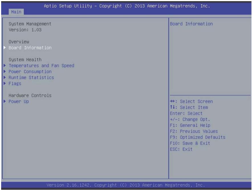
# B.1.3 System Management
![Main\nSystem Management\nVersion: 1.03\nOverview\n► Board Information\nSystem Health\n► Temperatures and Fan Speed\n► Power Consumption\n► Runtime Statistics\n► Flags\nHardware Controls\n► Power Up\nBoard Information\n+: Select Screen\n↑↓: Select Item\nEnter: Select\n+/-: Change Opt.\nF1: General Help\nF2: Previous Values\nF9: Optimized Defaults\nF10: Save & Exit\nESC: Exit\nVersion 2.16.1242. Copyright (C) 2013 American Megatrends, Inc.](.mxe-200-50-1z177-1000-200-en/56ad4cd49beec6f0755cfc8e3a3efa4d562748f0f5c3c0c63f7243d76fe1f945.jpg)

# Board Information

Provides SEMA Board Information.

# Temperatures and Fan Speed

Displays system temperatures and fan speed.

# Power Consumption

Provides system power consumption information.

# Runtime Statistics

Displays runtime statistics for the system.

# Flags

Shows SEMA flags.

# Power Up

Aptio Setup Utility - Copyright (C) 2013 American Megatrends, Inc.

Main

Power Up

Power-Up Watchdog

[Disabled]

ATTENTION: Pressing F12 during start up disables the Power Up Watchdog.

ECO Mode

[Disabled]

Power-Up Mode

[Turn On]

ATTENTION: The Power-Up Mode only has effect, if the module is in ATX-Mode.

The Power Up Watchdog resets the system after a certain amount of time after power up.

Pressing F12 during start up disables the Power Up Watchdog.

++: Select Screen

↑↓: Select Item
Enter: Select

+/-: Change Opt.

F1: General Help

F2: Previous Values

F9: Optimized Defaults

F10: Save & Exit

ESC: Exit

Version 2.16.1242. Copyright (C) 2013 American Megatrends, Inc.

# Power-Up Watchdog

Resets the system after a preset period after power up has passed.

# ECO Mode

Reduces power consumption of the system. After shutdown, at least 5 seconds must pass before restart can be executed.

# Power-Up Mode

Selecting Turn On starts the device automatically when the power supply is turned on.

Selecting Remain Off starts the device when the power button is pressed.

Selecting Last State powers up to the last power state

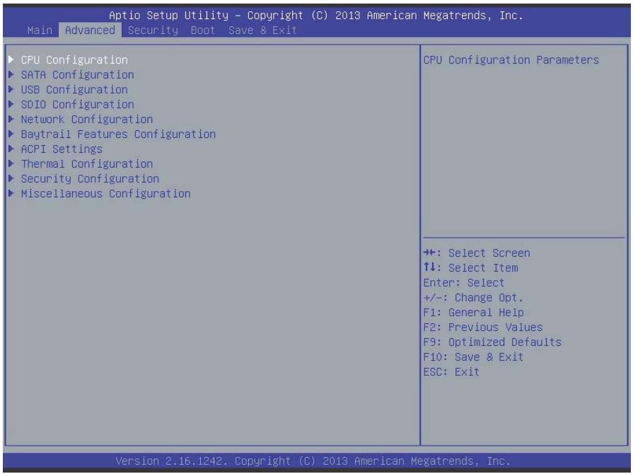
# B.2 Advanced
![Aptio Setup Utility - Copyright (C) 2013 American Megatrends, Inc.\nMain Advanced Security Boot Save & Exit\nCPU Configuration\nSATA Configuration\nUSB Configuration\nSDIO Configuration\nNetwork Configuration\nBaytrail Features Configuration\nACPI Settings\nThermal Configuration\nSecurity Configuration\nMiscellaneous Configuration\nCPU Configuration Parameters\n+: Select Screen\n↑↓: Select Item\nEnter: Select\n+/-: Change Opt.\nF1: General Help\nF2: Previous Values\nF9: Optimized Defaults\nF10: Save & Exit\nESC: Exit\nVersion 2.16.1242. Copyright (C) 2013 American Megatrends, Inc.](.mxe-200-50-1z177-1000-200-en/b1f7529c3edbc28d6610ab009d9cfefa19ab5bc2651131c777dd29306aa6cfbb.jpg)

![The image displays a standard warning sign featuring a yellow triangle with a black border. Inside the triangle is a large black exclamation point. Below the triangle, the word 'CAUTION:' is printed in black capital letters on a white background.](.mxe-200-50-1z177-1000-200-en/9a8316e59b733e5096678b68148b704ff2a179bd781242179b275b142d5e8372.jpg)

Setting incorrect or conflicting values in Advanced BIOS Setup may cause system malfunction.

# B.2.1 CPU Configuration

<table><tr><td colspan="2">Aptio Setup Utility - Copyright (C) 2013 American Megatrends, Inc.
Main Advanced Security Boot Save &amp; Exit</td></tr><tr><td>CPU Configuration
SATA Configuration
USB Configuration
SDIO Configuration
Network Configuration
Baytrail Features Configuration
ACPI Settings
Thermal Configuration
Security Configuration
Miscellaneous Configuration</td><td>CPU Configuration Parameters</td></tr><tr><td></td><td>+: Select Screen
↑↓: Select Item
Enter: Select
+/-: Change Opt.
F1: General Help
F2: Previous Values
F9: Optimized Defaults
F10: Save &amp; Exit
ESC: Exit</td></tr><tr><td colspan="2">Version 2.16.1242. Copyright (C) 2013 American Megatrends, Inc.</td></tr></table>

# Limit CPUID Maximum

Disabled for Windows XP.

# Execute Disable Bit

XD can prevent certain classes of malicious buffer overflow attacks when combined with a supporting OS (Windows Server 2003 SP1, Windows XP SP2, SuSE Linux 9.2, RedHat Enterprise 3 Update 3.)

# Intel Virtualization Technology

When enabled, a VMM can utilize the additional hardware capabilities provided by Vanderpool Technology

# Power Technology

Enables power management features.

# Socket 0 CPU Information

Aptio Setup Utility - Copyright (C) 2013 American Megatrends, Inc.

Advanced

Socket O CPU Information

Intel(R) Atom(TM) CPU E3826 @ 1.46GHz

CPU Signature 30679

Microcode Patch 901

Max CPU Speed 1460 MHz

Min CPU Speed 533 MHz

Processor Cores 2

Intel HT Technology Not Supported

Intel VT-x Technology Supported

L1 Data Cache 24 KB x 2

L1 Code Cache 32 kB x 2

L2 Cache 1024 KB × 1

L3 Cache Not Present

++: Select Screen

↑↓: Select Item

Enter: Select

+/-: Change Opt.

F1: General Help

F2: Previous Values

F9: Optimized Defaults

F10: Save & Exit

ESC: Exit

Version 2.16.1242. Copyright (C) 2013 American Megatrends, Inc.

<table><tr><td>Feature</td><td>Description</td></tr><tr><td>CPU Brand Name</td><td>Displays CPU rand name</td></tr><tr><td>CPU Signature</td><td>Displays CPU signature</td></tr><tr><td>Microcode Patch</td><td>Displays microcode patch</td></tr><tr><td>Max CPU speed</td><td>Displays max CPU speed</td></tr><tr><td>Min CPU speed</td><td>Displays min CPU speed</td></tr><tr><td>Processor Cores</td><td>Displays processor cores</td></tr><tr><td>Intel HT Technology</td><td>Displays Intel HT Technology support status</td></tr><tr><td>Intel VT-x Technology</td><td>Displays Intel VT-x Technology support status</td></tr><tr><td>L1 Data Cache</td><td>Displays cache info</td></tr><tr><td>L1 Code Cache</td><td>Displays cache info</td></tr><tr><td>L2 Cache</td><td>Displays cache info</td></tr><tr><td>L3 Cache</td><td>Displays cache info</td></tr></table>

# CPU Thermal Configuration

![Aptio Setup Utility - Copyright (C) 2013 American Megatrends, Inc.\nAdvanced\nCpu Thermal Configuration\nDTS    (Enabled)\nEnabled/Disable Digital\nThermal Sensor.\n+: Select Screen\n↑↓: Select Item\nEnter: Select\n+/-: Change Opt.\nF1: General Help\nF2: Previous Values\nF9: Optimized Defaults\nF10: Save & Exit\nESC: Exit\nVersion 2.16.1242. Copyright (C) 2013 American Megatrends, Inc.](.mxe-200-50-1z177-1000-200-en/b63bb041febccb09f67015aac6d50adaf8c45b25fa496971de3bfbb7c46a6efd.jpg)

# DTS

Enables/Disables Digital Thermal Sensor.

# PPM Configuration

![Aptio Setup Utility - Copyright (C) 2013 American Megatrends, Inc.\nAdvanced\nPPM Configuration\nCPU C state Report (Enabled)\nMax CPU C-state ( C1)\nSoix (Disabled)\nEnable/Disable CPU C state\nreport to OS\n+: Select Screen\n↑↓: Select Item\nEnter: Select\n+/-: Change Opt.\nF1: General Help\nF2: Previous Values\nF9: Optimized Defaults\nF10: Save & Exit\nESC: Exit\nVersion 2.16.1242. Copyright (C) 2013 American Megatrends, Inc.](.mxe-200-50-1z177-1000-200-en/3cf54c4ccfdec507703e552f3aabb853c2b76fb27ccebd7267ea847e688ef437.jpg)

# CPU C state Report

Enables/Disables reports of CPU C state to OS.

# Max CPU C-state

Determines which Max C state the processor supports.

# Soix

Enables/Disables CPU S0ix state

# B.2.2 SATA Configuration

![Aptio Setup Utility - Copyright (C) 2013 American Megatrends, Inc.\nAdvanced\nIDE Configuration\nSerial-ATA (SATA)    (Enabled)\nSATA Speed Support    (Gen2)\nSATA ODD Port    (No ODD)\nSATA Mode    (AHCI Mode)\nSerial-ATA Port 0    (Enabled)\nSATA Port0 HotPlug    (Disabled)\nSATA Port0\nInnoDisk Corp. (16.0GB)\nEnable / Disable Serial ATA\n+: Select Screen\n↑↓: Select Item\nEnter: Select\n+/-: Change Opt.\nF1: General Help\nF2: Previous Values\nF9: Optimized Defaults\nF10: Save & Exit\nESC: Exit\nVersion 2.16.1242, Copyright (C) 2013 American Megatrends, Inc.](.mxe-200-50-1z177-1000-200-en/48f7dd1317f05c60c16e8ca92ec20e9fffd6841b167c42621192b3f16a75d155.jpg)

# Serial-ATA (SATA)

Enables/Disables Serial ATA

# SATA Speed Support

Selects SATA Speed Support Gen1 or Gen2

# SATA Mode

Selects IDE/AHCI modes

# Serial-ATA Port 0

Enables/Disables Serial ATA Port 0

# SATA Port0 HotPlug

Enables/Disables Port O HotPlug capability

# B.2.3 USB Configuration

<table><tr><td colspan="2">Aptio Setup Utility - Copyright (C) 2013 American Megatrends, Inc. Advanced</td></tr><tr><td>USB ConfigurationUSB Module Version 8.11.01USB Devices:1 Drive, 1 Keyboard, 1 Mouse, 2 HubsLegacy USB Support [Enabled]XHCI Hand-off [Enabled]EHCI Hand-off [Disabled]USB Mass Storage Driver Support [Enabled]USB hardware delays and time-outs:USB transfer time-out [20 sec]Device reset time-out [20 sec]Device power-up delay [Auto]USB Host Controller ConfigurationUSB Host Controller ConfigurationMass Storage Devices:JetFlashTranscend 4GB 8.07 [Auto]</td><td>Enables Legacy USB support.AUTO option disables legacysupport if no USB devices areconnected.DISABLE option willkeep USB devices availableonly for EFI applications.++: Select Screen↑↓: Select ItemEnter: Select+/-: Change Opt.F1: General HelpF2: Previous ValuesF9: Optimized DefaultsF10: Save &amp; ExitESC: Exit</td></tr></table>

# Legacy USB Support

Selecting AUTO disables legacy support if no USB devices are connected, and DISABLE keeps USB devices available for only EFI applications.

# XHCI Hand-Off

A workaround for OSs without XHCI handoff support. XHCI ownership change should be claimed by XHCI driver.

# EHCI Hand-Off

A workaround for OSs without EHCl handoff support. EHCl ownership change should be claimed by EHCl driver

# USB Mass Storage Driver Support

Enables/disables USB Mass Storage Driver support.

# USB transfer time-out

Timeout value for Control, Bulk, and Interrupt transfers.

# Device reset time-out

USB mass storage device Start Unit command timeout.

# Device power-up delay

Maximum time the device will take before reporting to the Host Controller. Selecting Auto employs the default value, ie for a Root port, 100 ms and for a Hub port the delay is taken from Hub descriptor.

# USB Host Controller Configuration

Aptio Setup Utility - Copyright (C) 2013 American Megatrends, Inc.

Advanced

```ini
USB Host Controller Configuration
XHCI Mode [Smart Auto]
USB2 Link Power Management [Enabled]
USB 2.0(EHCI) Support [Disabled]
USB Per Port Control [Enabled]
USB Port 0 [Enabled]
USB Port 1 [Enabled]
USB Port 2 [Enabled]
USB Port 3 [Enabled]
```

```txt
Mode of operation of xHCI controller
```

```txt
++: Select Screen
↑↓: Select Item
Enter: Select
+/-: Change Opt.
F1: General Help
F2: Previous Values
F9: Optimized Defaults
F10: Save & Exit
ESC: Exit
```

Version 2.16.1242. Copyright (C) 2013 American Megatrends, Inc.

# XHCI mode

Sets operating mode of XHCI controller.

# USB2 Link Power Management

Enables/disables USB2 Link Power Management.

# USB Per Port Control

Controls each USB port 0 to 3, Enabling USB per port, or Disable by USB port x settings.

# USB Port #0\~3

Enables/disables USB Ports 0 to 3.

# B.2.4 SDIO Configuration

![Aptio Setup Utility - Copyright (C) 2013 American Megatrends, Inc.\nAdvanced\nSDIO Configuration\nSDIO Access Mode (Auto)\nAuto Option: Access SD device\nin DMA mode if controller\nsupports it,otherwise in PIO\nmode.DMA Option: Access SD\ndevice in DMA mode.PIO Option:\nAccess SD device in PIO mode.\n+: Select Screen\n↑↓: Select Item\nEnter: Select\n+/-: Change Opt.\nF1: General Help\nF2: Previous Values\nF9: Optimized Defaults\nF10: Save & Exit\nESC: Exit\nVersion 2.16.1242, Copyright (C) 2013 American Megatrends, Inc.](.mxe-200-50-1z177-1000-200-en/fda42e4b3290a7c890b402b43208d908e3f69da5e35387ef7faa8ad03c2e7aef.jpg)

# SDIO Access Mode

Selecting Auto accesses SD device in DMA mode if controller supported, otherwise in PIO mode. Selecting DMA accesses SD device in DMA mode, and selecting PIO Accesses SD device in PIO mode.

# B.2.5 Network Configuration

![Aptio Setup Utility - Copyright (C) 2013 American Megatrends, Inc.\nAdvanced\nNetwork Stack (Disabled) Enable/Disable UEFI Network\nStack\n+: Select Screen\n↑↓: Select Item\nEnter: Select\n+/-: Change Opt.\nF1: General Help\nF2: Previous Values\nF9: Optimized Defaults\nF10: Save & Exit\nESC: Exit\nVersion 2.16.1242. Copyright (C) 2013 American Megatrends, Inc.](.mxe-200-50-1z177-1000-200-en/14d887371f521d46e972a71154932a9e01d3332e2974f26ce0d13dbe0fa34049.jpg)

# Network Stack

Enables/disables UEFI Network Stack

# B.2.6 Baytrail Feature Configuration

![Aptio Setup Utility - Copyright (C) 2013 American Megatrends, Inc.\nAdvanced\nLPSS & SCC Devices Mode (PCI mode)\nSCC Configuration\nSCC SD Card Support (Enabled)\nSDR25 Support for SDCard (Disabled)\nDDR50 Support for SDCard (Enabled)\nMIPI HSI Support (Disabled)\nLPSS Configuration\nLPSS HSUART #1 Support (Enabled)\nLPSS HSUART #2 Support (Enabled)\nLPSS & SCC Devices Mode\nSettings\n+: Select Screen\n↑↓: Select Item\nEnter: Select\n+/-: Change Opt.\nF1: General Help\nF2: Previous Values\nF9: Optimized Defaults\nF10: Save & Exit\nESC: Exit\nVersion 2.16.1242. Copyright (C) 2013 American Megatrends, Inc.](.mxe-200-50-1z177-1000-200-en/d19ba03e928e760c316dbd8bc791e450548d8b082a993436dea75482aeecb2f2.jpg)

# LPSS & SCC Devices Mode

Sets LPSS & SCC Device Mode.

# SCC SD Card Support

Enables/Disables SCC SD Card support

# DDR50 Support for SD Card

Enables/Disables DDR50 capability in SD card controller.

# MIPI HSI Support

Enables/Disables MIPI HSI support.

# LPSS HSUART # Support

Enables/Disables LPSS HSUART # support.

# HSUART Port Mode

Sets HSUART port mode.

# B.2.7 ACPI Setting

<table><tr><td colspan="2">Aptio Setup Utility - Copyright (C) 2013 American Megatrends, Inc. Advanced</td></tr><tr><td rowspan="2">ACPI SettingsEnable ACPI Auto Configuration [Disabled]Enable Hibernation [Enabled]ACPI Sleep State [S3 (Suspend to RAM)]Lock Legacy Resources [Disabled]</td><td>Enables or Disables BIOS ACPI Auto Configuration.</td></tr><tr><td>+: Select Screen↑↓: Select ItemEnter: Select+/-: Change Opt.F1: General HelpF2: Previous ValuesF9: Optimized DefaultsF10: Save &amp; ExitESC: Exit</td></tr></table>

# Enable ACPI Auto Configuration

Enables/Disables BIOS ACPI Auto Configuration.

# Enable Hibernation

Enables/Disables hibernation capability (OS/S4 Sleep State), when supported by OS.

# ACPI Sleep State

Selects the highest ACPI sleep state the system will enter when SUSPEND is selected.

# Lock Legacy Resources

Enables/Disables Legacy Resource lock.

# B.2.8 Thermal Configuration

![Aptio Setup Utility - Copyright (C) 2013 American Megatrends, Inc.\nAdvanced\nThermal Configuration Parameters\nCritical Trip Point (Disabled)\nPassive Trip Point (Disabled)\nActive Cooling Trip Point (BMC Default)\nThis value controls the\ntemperature of the ACPI\ncritical Trip Point in which\nthe OS will shut the system\noff.\n+: Select Screen\n↑↓: Select Item\nEnter: Select\n+/-: Change Opt.\nF1: General Help\nF2: Previous Values\nF9: Optimized Defaults\nF10: Save & Exit\nESC: Exit\nVersion 2.16.1242. Copyright (C) 2013 American Megatrends, Inc.](.mxe-200-50-1z177-1000-200-en/fd9aea2e16aa01ac3b2d237ae76fbc576ef97cbfd34d772a936cc74670f44b99.jpg)

# Critical Trip Point

Sets the ACPI critical trip point temperature at which the OS will shut the system down.

# Passive Trip Point

Sets the temperature of the ACPI critical trip point at which the OS will begin throttling the processor

# Active Cooling Trip Point

Sets the Active Cooling trip point.

# B.2.9 Security Configuration

![Main\nAptio Setup Utility - Copyright (C) 2013 American Megatrends, Inc.\nIntel(R) TXE Configuration\nTXE (Enabled)\nTXE HMRFPO (Disabled)\nTXE Firmware Update (Enabled)\nTXE EOP Message (Enabled)\nTXE Unconfiguration Perform\nIntel(R) Anti-Theft Technology Configuration\nIntel(R) AT Suspend Mode (Disabled)\nSend EOP Message Befor Enter OS\n+: Select Screen\n↑↓: Select Item\nEnter: Select\n+/-: Change Opt.\nF1: General Help\nF2: Previous Values\nF9: Optimized Defaults\nF10: Save & Exit\nESC: Exit\nVersion 2.16.1242. Copyright (C) 2013 American Megatrends, Inc.](.mxe-200-50-1z177-1000-200-en/ccf32f3f3cf8944f740f38005666560bb616e985fb922d88037acf2b91696375.jpg)

# TXE

Enables/Disables TXE firmware

# TXE HMRFBO

Enables/Disables TXE HMRFBO

# TXE Firmware Update

Enables/Disables TXE firmware update.

# TXE EOP Message

Sends EOP Message Before OS starts up.

# TXE Unconfiguration Perform

Reverts TXE Settings to factory defaults.

# B.2.10 Miscellaneous Configuration

![Aptio Setup Utility - Copyright (C) 2013 American Megatrends, Inc.\nAdvanced\nMiscellaneous Configuration\nOS Selection (Windows 7)\nOS Selection\n+: Select Screen\n↑↓: Select Item\nEnter: Select\n+/-: Change Opt.\nF1: General Help\nF2: Previous Values\nF9: Optimized Defaults\nF10: Save & Exit\nESC: Exit\nVersion 2.16.1242. Copyright (C) 2013 American Megatrends, Inc.](.mxe-200-50-1z177-1000-200-en/6f3b9ab4722d114d72801485541a4afa5033bd1aa0ec8137500cdaca65253b48.jpg)

# OS Selection

Selects active OS.

# B.3 Security

<table><tr><td colspan="2">Aptio Setup Utility - Copyright (C) 2013 American Megatrends, Inc.Main Advanced Security Boot Save &amp; Exit</td></tr><tr><td rowspan="2">Password DescriptionIf ONLY the Administrator&#x27;s password is set,then this only limits access to Setup and isonly asked for when entering Setup.If ONLY the User&#x27;s password is set, then thisis a power on password and must be entered toboot or enter Setup. In Setup the User willhave Administrator rights.The password length must bein the following range:Minimum length 3Maximum length 20Administrator PasswordUser Password</td><td rowspan="2">Set Administrator Password++: Select Screen↑↓: Select ItemEnter: Select+/-: Change Opt.F1: General HelpF2: Previous ValuesF9: Optimized DefaultsF10: Save &amp; ExitESC: Exit</td></tr><tr></tr></table>

![The image displays a white document icon with horizontal lines representing text and a folded top-right corner. A large red checkmark is superimposed over the left side of the page.](.mxe-200-50-1z177-1000-200-en/61ec7191e2e2202036c99bd69b024933a35c2a23224e1b5030452713b2b2bdaa.jpg)
NOTE:

If only the Administrator's password is set, only access to Setup is limited and authorization requested only when entering Setup. If only the User's password is set, a password must be entered to boot or enter setup. In Setup the user has Administrator rights.

# Administrator Password

Sets Administrator password.

# User Password

Sets boot/setup User password.

# B.4 Boot

![Aptio Setup Utility - Copyright (C) 2013 American Megatrends, Inc.\nMain Advanced Security Boot Save & Exit\nBoot Configuration\nSetup Prompt Timeout 1\nBootup NumLock State (On)\nQuiet Boot (Enabled)\nFast Boot (Disabled)\n► CSM Configuration\nBoot Option Priorities\nBoot Option #1 (UEFI: JetFlashTrans...)\nBoot Option #2 (P0: InnoDisk Corp. ...)\nBoot Option #3 (UEFI: Built-in EFI ...)\nBoot Option #4 (JetFlashTranscend 4...)\n► Add New Boot Option\n► Delete Boot Option\nNumber of seconds to wait for\nsetup activation key.\n65535(0xFFFF) means indefinite\nwaiting.\n+: Select Screen\n↑↓: Select Item\nEnter: Select\n+/-: Change Opt.\nF1: General Help\nF2: Previous Values\nF9: Optimized Defaults\nF10: Save & Exit\nESC: Exit\nVersion 2.16.1242. Copyright (C) 2013 American Megatrends, Inc.](.mxe-200-50-1z177-1000-200-en/2f16c8f41bbe3363544a87de77f002fecbbde16168f58965628184220c9c02de.jpg)

# Setup Prompt Timeout

Sets number of seconds to wait for setup activation key.

# Bootup Num-Lock State

Allows Number Lock setting to be modified during boot.

# Quiet Boot

When Disabled, directs BIOS to display POST messages, when Enabled, directs BIOS to display the OEM logo.

# Fast Boot

Enables or disables boot with initialization of the minimal set of devices required to launch active boot option. Has no effect on BBS boot options.

# Boot Option Priorities

Specifies the priority of boot devices, with all installed boot devices detected during POST and displayed, where selecting Boot Option # specifies the desired boot device.

# CSM Configuration

<table><tr><td colspan="2">Main</td></tr><tr><td colspan="2">Compatibility Support Module Configuration</td></tr><tr><td>CSM Support</td><td>[Enabled]</td></tr><tr><td>CSM16 Module Version</td><td>07.75</td></tr><tr><td>GateA20 Active</td><td>[Upon Request]</td></tr><tr><td>Option ROM Messages</td><td>[Force BIOS]</td></tr><tr><td>INT19 Trap Response</td><td>[Immediate]</td></tr><tr><td>Boot option filter</td><td>[UEFI and Legacy]</td></tr><tr><td>Option ROM execution</td><td></td></tr><tr><td>Network</td><td>[UEFI only]</td></tr><tr><td>Storage</td><td>[UEFI only]</td></tr><tr><td>Video</td><td>[Legacy first]</td></tr><tr><td>Other PCI devices</td><td>[UEFI only]</td></tr></table>

# CSM Support

Enables/disables CSM support.

# GateA20 Active

Selecting Upon Request allows GA20 to be disabled using BIOS services, and selecting Always disallows disabling of GA20, useful when any RT code exceeding 1MB is executed.

# Option ROM Messages

Sets display mode for Options.

# INT19 Trap Response

Sets BIOS reaction to INT19 trapping by Option ROM, where selecting Immediate executes the trap immediately, and Postponed executes the trap during a legacy boot.

# Boot option filter

Sets Legacy/UEFI ROM priority.

# Network

Sets execution of UEFI and Legacy PXE OpROM.

# Storage

Sets execution of UEFI and Legacy Storage OpROM.

# Video

Sets execution of UEFI and Legacy Video OpROM.

# Other PCI devices

Determines OpROM execution policy for devices other than Network, Storage, or Video.

# B.5 Exit

<table><tr><td colspan="2">Aptio Setup Utility - Copyright (C) 2013 American Megatrends, Inc.</td></tr><tr><td colspan="2">Main Advanced Security Boot Save &amp; Exit</td></tr><tr><td>Save Changes and ExitDiscard Changes and ExitSave Changes and ResetDiscard Changes and ResetSave OptionsSave ChangesDiscard ChangesRestore DefaultsSave as User DefaultsRestore User DefaultsBoot OverrideP0: InnoDisk Corp. - mSATA 3MEUEFI: Built-in EFI ShellUEFI: JetFlashTranscend 4GB 8.07JetFlashTranscend 4GB 8.07Launch EFI Shell from filesystem deviceReset System with ME disable ModeMEUD000</td><td>Exit system setup after saving the changes.++: Select Screen↑↓: Select ItemEnter: Select+/-: Change Opt.F1: General HelpF2: Previous ValuesF9: Optimized DefaultsF10: Save &amp; ExitESC: Exit</td></tr></table>

# Save Changes and Exit

Exits Setup after saving changes.

# Discard Changes and Exit

Exits Setup without saving any changes.

# Save Changes and Reset

Resets the system after saving changes.

# Discard Changes and Reset

Resets system setup without saving any changes.

# Save Changes

Saves all changes made to Setup options.

# Discard Changes

Discards changes made to Setup options.

# Restore Defaults

Returns all BIOS options to Default settings, providing maximum system stability with limited performance. Applicable in the event of system configuration problems.

# Save as User Defaults

Save changes as User Defaults.

# Restore User Defaults

Restores User Defaults to all Setup options.

# Launch EFI Shell from filesystem device

Initiates launch of EFI Shell application (Shellx64.efi) from an available filesystem device.

# Reset System with ME disable ModeMEUD000

ME runs in temporary disable mode, not applicable if ME Ignition FWMEUD001.

# Important Safety Instructions

For user safety, please read and follow all instructions, WARNINGS, CAUTIONS, and NOTES marked in this manual and on the associated equipment before handling/operating the equipment.

▶ Read these safety instructions carefully.
- Keep this user’s manual for future reference.
▶ Read the specifications section of this manual for detailed information on the operating environment of this equipment.
▶ When installing/mounting or uninstalling/removing equipment:

▷ Turn off power and unplug any power cords/cables.

▶ To avoid electrical shock and/or damage to equipment:

▷ Keep equipment away from water or liquid sources;
▷ Keep equipment away from high heat or high humidity;
▷ Keep equipment properly ventilated (do not block or cover ventilation openings);

▶ Make sure to use recommended voltage and power source settings;

▶ Always install and operate equipment near an easily accessible electrical socket-outlet;

▷ Secure the power cord (do not place any object on/over the power cord);

▶ Only install/attach and operate equipment on stable surfaces and/or recommended mountings; and,

▷ If the equipment will not be used for long periods of time, turn off and unplug the equipment from its power source.

▶ Never attempt to fix the equipment. Equipment should only be serviced by qualified personnel.
▶ A Lithium-type battery may be provided for uninterrupted, backup or emergency power.

![This image shows a standard warning sign. At the top is a red triangle containing a white exclamation point. Below the triangle, the word 'WARNING:' is printed in black capital letters.](.mxe-200-50-1z177-1000-200-en/61ab7bf0f98f7efed667921afbe6c09c82ae43078af07298ef8d4b1b33506e2e.jpg)

Risk of explosion if battery is replaced with an incorrect type; please dispose of used batteries appropriately.

▶ Equipment must be serviced by authorized technicians when:

The power cord or plug is damaged;
▷ Liquid has penetrated the equipment;
▷ It has been exposed to high humidity/moisture;
$\triangleright$ It is not functioning or does not function according to the user's manual;
▷ It has been dropped and/or damaged; and/or,
▷ It has an obvious sign of breakage.

Please pay strict attention to all warnings and advisories appearing on the device, to avoid injury or damage.

![Yellow triangular warning sign with black smoke symbol indicating hazard or stress](.mxe-200-50-1z177-1000-200-en/1939fb4c7bacc94b3b686eeb8d0a0c553dcb95dfe6e2d3eb503e9f914c1fc8b3.jpg)

# WARNING

# Burn hazard.

Touching this surface could result in bodily injury. To reduce risk of injury allow the surface to cool before touching.

# Getting Service

Contact us should you require any service or assistance.

# ADLINK Technology, Inc.

Address: 9F, No.166 Jian Yi Road, Zhonghe District
New Taipei City 235, Taiwan
新北市中和區建一路 166 號 9 樓

Tel: +886-2-8226-5877

Fax: +886-2-8226-5717

Email: service@adlinktech.com

# Ampro ADLINK Technology, Inc.

Address: 5215 Hellyer Avenue, #110
San Jose, CA 95138, USA

Tel: +1-408-360-0200

Toll Free: +1-800-966-5200 (USA only)

Fax: +1-408-360-0222

Email: info@adlinktech.com

# ADLINK Technology (China) Co., Ltd.

Address: 上海市浦东新区张江高科技园区芳春路300号(201203)300 Fang Chun Rd., Zhangjiang Hi-Tech Park Pudong New Area, Shanghai, 201203 China

Tel: +86-21-5132-8988

Fax: +86-21-5132-3588

Email: market@adlinktech.com

# ADLINK Technology Beijing

Address: 北京市海淀区上地东路1号盈创动力大厦E座801室(100085)Rm.801,Power Creative E,No.1 Shang Di East Rd.Beijing,100085 China

Tel: +86-10-5885-8666

Fax: +86-10-5885-8626

Email: market@adlinktech.com

# ADLINK Technology Shenzhen

Address: 深圳市南山区科技园南区高新南七道 数字技术园
A1 栋 2 楼 C 区 (518057)
2F, C Block, Bldg. A1, Cyber-Tech Zone, Gao Xin Ave. Sec. 7
High-Tech Industrial Park S., Shenzhen, 518054 China

Tel: +86-755-2643-4858

Fax: +86-755-2664-6353

Email: market@adlinktech.com

# LiPPERT ADLINK Technology GmbH

Address: Hans-Thoma-Strasse 11, D-68163
Mannheim, Germany

Tel: +49-621-43214-0

Fax: +49-621 43214-30

Email: emea@adlinktech.com

# ADLINK Technology, Inc. (French Liaison Office)

Address: 6 allée de Londres, Immeuble Ceylan

91940 Les Ulis, France

Tel: +33 (0) 1 60 12 35 66

Fax: +33 (0) 1 60 12 35 66

Email: france@adlinktech.com

# ADLINK Technology Japan Corporation

Address: 〒101-0045 東京都千代田区神田鍛冶町 3-7-4

神田 374 ビル 4F

KANDA374 Bldg. 4F, 3-7-4 Kanda Kajicho,

Chiyoda-ku, Tokyo 101-0045, Japan

Tel: +81-3-4455-3722

Fax: +81-3-5209-6013

Email: japan@adlinktech.com

# ADLINK Technology, Inc. (Korean Liaison Office)

Address: 137-881 서울시 서초구 서초대로 326,802(서초동, 모인터빌딩)

802, Mointer B/D, 326 Seocho-daero, Seocho-Gu,

Seoul 137-881, Korea

Tel: +82-2-2057-0565

Fax: +82-2-2057-0563

Email: korea@adlinktech.com

# ADLINK Technology Singapore Pte. Ltd.

Address: 84 Genting Lane #07-02A, Cityneon Design Centre

Singapore 349584

Tel: +65-6844-2261

Fax: +65-6844-2263

Email: singapore@adlinktech.com

# ADLINK Technology Singapore Pte. Ltd. (Indian Liaison Office)

Address: #50-56, First Floor, Spearhead Towers

Margosa Main Road (between 16th/17th Cross)

Malleswaram, Bangalore - 560 055, India

Tel: +91-80-65605817, +91-80-42246107

Fax: +91-80-23464606

Email: india@adlinktech.com

# ADLINK Technology, Inc. (Israeli Liaison Office)

Address: 27 Maskit St., Corex Building

PO Box 12777

Herzliya 4673300, Israel

Tel: +972-54-632-5251

Fax: +972-77-208-0230

Email: israel@adlinktech.com

# ADLINK Technology, Inc. (UK Liaison Office)

Tel: +44 774 010 59 65

Email: UK@adlinktech.com
[🔗 Link to the original document](.mxe-200-50-1z177-1000-200-en/mxe-200-50-1z177-1000-200-en.pdf)