# MXN-4100

# Switch Sled with

# Intel® Ethernet Multi-Host Controller

# User’s Manual

![Back view of a computer motherboard with visible CPU socket, heatsink, and drive slots (no text or symbols)](.mxn-4100-50-1z270-1000-10/620fdd446f6dae043f50f9ae1590389996a503667a9a235c6b81bbde86a7536a.jpg)

Manual Revision: 1.0

Revision Date: March 28, 2019

Part No.: 50-1Z270-1000

# Preface

# Copyright 2019 ADLINK Technology, Inc.

This document contains proprietary information protected by copyright. All rights are reserved. No part of this manual may be reproduced by any mechanical, electronic, or other means in any form without prior written permission of the manufacturer.

# Disclaimer

The information in this document is subject to change without prior notice in order to improve reliability, design, and function and does not represent a commitment on the part of the manufacturer.

In no event will the manufacturer be liable for direct, indirect, special, incidental, or consequential damages arising out of the use or inability to use the product or documentation, even if advised of the possibility of such damages.

# Environmental Responsibility

ADLINK is committed to fulfill its social responsibility to global environmental preservation through compliance with the European Union's Restriction of Hazardous Substances (RoHS) directive and Waste Electrical and Electronic Equipment (WEEE) directive.

Environmental protection is a top priority for ADLINK. We have enforced measures to ensure that our products, manufacturing processes, components, and raw materials have as little impact on the environment as possible. When products are at their end of life, our customers are encouraged to dispose of them in accordance with the product disposal and/or recovery programs prescribed by their nation or company.

![Simple line drawing of a trash bin with two crossed lines indicating no waste or prohibition (no text or symbols)](.mxn-4100-50-1z270-1000-10/5e9d31151bacc2fe84791e33151ee13c79d10f4224027386ff157abe06698aeb.jpg)

![The image displays a solid black rectangle centered horizontally on a white background. There is no text present in the image.](.mxn-4100-50-1z270-1000-10/c453226e49e7067aaa8ef89ecaca7b7036929828eda98c13dabfb820d4dfd5a9.jpg)

Battery Labels (for products with battery)

![Symbol of a trash bin crossed out by two diagonal lines (no text or numbers present)](.mxn-4100-50-1z270-1000-10/685cd79e9d5d7486bfacfc8d78661a40f256194ec593dcd1a7583057e574880a.jpg)

![The image shows a black outline of a square containing the universal recycling symbol. Inside the square, three arrows form a triangular loop, with each arrow bent in the middle and pointing in a clockwise direction.](.mxn-4100-50-1z270-1000-10/b9f910a9e60c5be252c035e91eeab89b72c8c7fc7adfd5a46d13b98c7d3eb1a6.jpg)
Li-ion

![RECYCLE\nRBRC\nLi-ion\n7.800.822.8837](.mxn-4100-50-1z270-1000-10/9a30c94aad532bbdd9857632e2dd19a64d77e2379546d2540d6eac00de4152a2.jpg)

![The image displays a black square icon. Inside, a white graphic consists of four arrows pointing diagonally outward toward the four corners, crossing at the center to form an 'X'. The black background forms four additional arrow shapes pointing cardinally inward toward the center from the top, bottom, left, and right sides.](.mxn-4100-50-1z270-1000-10/b43056c96c59889bf191406df9fa4feb6b725bd68d5425d84abd698197101c90.jpg)
廢電池請回收

# California Proposition 65 Warning

![The image shows a standard warning sign featuring a yellow equilateral triangle with a thick black border. Centered inside the triangle is a large, bold black exclamation point.](.mxn-4100-50-1z270-1000-10/7d052be3299cb40d393df5422f4e5b8cc1c24acf40825b7494d81f8c90fd1dc6.jpg)

WARNING: This product can expose you to chemicals including acrylamide, arsenic, benzene, cadmium, Tris(1,3-dichloro-2-propyl)phosphate (TDCPP), 1,4- Dioxane, formaldehyde, lead, DEHP, styrene, DINP, BBP, PVC, and vinyl materials, which are known to the State of California to cause cancer, and acrylamide, benzene, cadmium, lead, mercury, phthalates, toluene, DEHP, DIDP, DnHP, DBP, BBP, PVC, and vinyl materials, which are known to the State of California to cause birth defects or other reproductive harm. For more information go to www.P65Warnings.ca.gov.

# Trademarks

Product names mentioned herein are used for identification purposes only and may be trademarks and/or registered trademarks of their respective companies.

Revision History

<table><tr><td>Revision</td><td>Release Date</td><td>Description of Change(s)</td></tr><tr><td>1.0</td><td>2019-03-28</td><td>Initial release</td></tr></table>

# Table of Contents

# Preface ...

# 1 Overview ..... 5

1.1 Introduction .. . 5
1.2 Specifications.. .. 6
1.3 Switch Sled Front Panel.. 7
1.4 Switch Sled Layout .. . 8
1.5 IO Expansion Module.. 9
1.6 ADLINK PacketManager.. . 10

# 2 Getting Started... .11

2.1 Preparing the Switch Sled.. ..11

2.1.1 Installing a COMe Module . ..11
2.1.2 Installing an mSATA Module.. ..12
2.1.3 Installing a CMM Module . ..13
2.1.4 Installing an I/O Expansion Module. ..14

2.2 Front Panel .. . 15
2.3 Inserting and Removing the Switch Sled ..

# 3 Powering Up the Switch Sled .. . 17

3.1 Power-Up Behavior.. . 17
3.2 Health/Status Indicators and Buttons... . 18

# 4 Using the Switch Sled.. . 19

4.1 Login to the Switch System.. . 19

4.1.1 Login Via Serial Port . ..19
4.1.2 Local Login . ..21
4.1.3 Via Network Port ................ ..23

4.2 Switch System IP Setup.. . 24
4.3 COMe OS Version Check .. . 25

4.4 PacketManager on the Switch Sled.. .. 26

4.4.1 Check PacketManager Installation Version.. ..26
4.4.2 Command Line Interface and Configure Mode . .27
4.4.3 Get Help and Check Version . ..28

4.5 Fabric Mode.. .. 30

# 5 Maintenance... 32

5.1 Hot-Swapping the Switch Sled.. . 32
5.2 Updating the Switch System BIOS . .. 33

# Safety Instructions .... . 34

# Consignes de Sécurité Importantes ..... . 36

# Getting Service ..... . 38

# 1 Overview

# 1.1 Introduction

The ADLINK MXN-4100 is a high-throughput high IO density switch sled that functions as an interconnect for four compute nodes on the CSA-7400 Network Appliance and provides up to 4x 100G ports on front panel. The MXN-4100 is a building block used in the construction of next generation high-performance firewalls and virtualized telecom elements.

The main features of the MXN-4100 are summarized as follows:

• Up to two MXN-4100 switch sleds are supported on the CSA-7400 (dual redundant)
• Data plane supports 4x 50Gb Ethernet throughput to four CPU sleds, up to 4x100G ports on front plane
Control plane supports independent 1G links that connect four compute nodes, Chassis Management Modules (CMM) and 2x RJ45 ports on front panel
• Supports accelerated processing of NVGRE/VXLAN tunneling protocols to meet the needs of Layer 2 connectivity for cloud computing
ADLINK PacketManager software provides commonly used Layer 2 and Layer 3 switch protocol stacks and control APIs to accelerate application development
Supports smart system management via on-board CMM module for remote system diagnosis, shutdown, and startup

1.2 Specifications

<table><tr><td colspan="2">Core System</td></tr><tr><td>Switch</td><td>Intel® Ethernet Multi-host Controller FM10840 (formerly Red Rock Canyon) with 900Mbps bandwidth &amp; 4x PCIe x8 Gen3</td></tr><tr><td>CMM</td><td>Chassis management module (AST-1250)</td></tr><tr><td>COM Express Module</td><td>COM Express module with Type 6 interface as local management (optional)Intel® CoreTM i7-4700EQ 2.4GHz, 4cores, GT2Intel® Celeron® 2002E 1.5GHz, 2cores, GT12x SODIMM 1600/1333MHz DDR3, up to 16GB</td></tr><tr><td>Operating System</td><td>Linux Kernel 2.6 or above</td></tr><tr><td colspan="2">I/O Interfaces</td></tr><tr><td>Data Plane</td><td>4x 100GBASE-SR4/100GBASE-LR4 QSFP28 ports (front panel)NIM-1610: Switch I/O extension card with 16x 10G SFP+(NIM-0440 with 4x 40G QSFP+ optional)</td></tr><tr><td>Control Plane</td><td>6x 1G to four CPU sleds, COMe and CMM2x RJ-45 ports on switch panel</td></tr><tr><td>USB</td><td>1x USB 2.0 (one can be used as a console port)1x USB serial console port to COMe module and CMM</td></tr><tr><td>Storage</td><td>2x mSATA as local storage</td></tr><tr><td>Backplane</td><td>4x PCIe x8 Gen3 to CPU nodes</td></tr><tr><td colspan="2">Control Buttons and LEDs</td></tr><tr><td>Reset</td><td>1x Reset Button (front)1x Hot Swap (front, see 5.1 Hot-Swapping the Switch Sled)</td></tr><tr><td>LEDs</td><td>Power, Active/Standby (A/S), Hot Swap Status (ATN), Alarm (I, II, III)</td></tr><tr><td colspan="2">Mechanical</td></tr><tr><td>Form Factor</td><td>213.9mmx 40.44mm x 432.1mm (W x H x D)</td></tr></table>

# 1.3 Switch Sled Front Panel

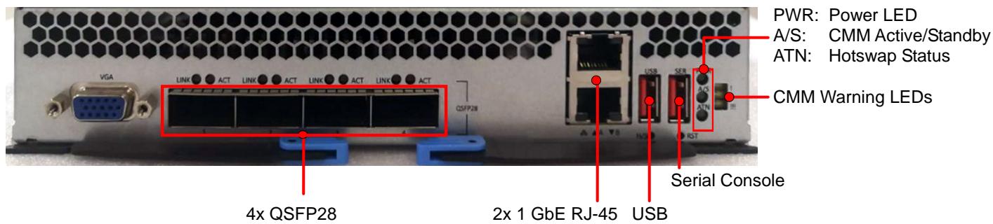
![PWR: Power LED\nA/S: CMM Active/Standby\nATN: Hotswap Status\nCMM Warning LEDs\n4x QSFP28\n2x 1 GbE RJ-45 USB\nSerial Console](.mxn-4100-50-1z270-1000-10/afccbf9a2859618f715e585e3c17b93bdb60ea9fc716c023fd8daab4c219bc67.jpg)

# 1.4 Switch Sled Layout

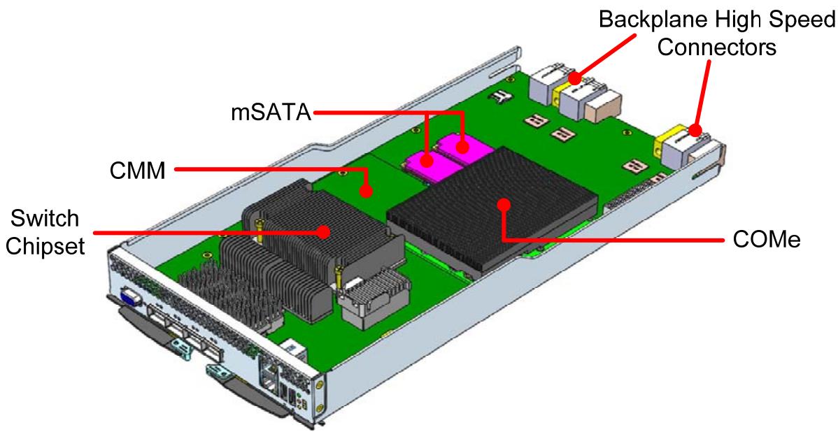
![Backplane High Speed\nConnectors\nmSATA\nCMM\nSwitch\nChipset\nCOMe](.mxn-4100-50-1z270-1000-10/a899d2c3cef73f10f5d95a624d264fd6f1ed49759e59484029fcc130a6ff751e.jpg)

# 1.5 IO Expansion Module

NIM-1610

16x 10G SFP+
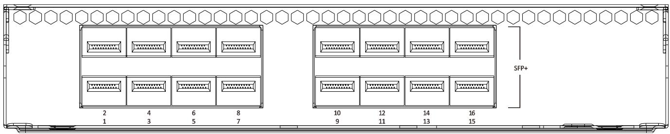
![SFP+\n2 4 6 8\n1 3 5 7\n10 12 14 16\n9 11 13 15](.mxn-4100-50-1z270-1000-10/f5bf1a77ab423bb0ad871d115c0043073a210841d877f7e4f786a8e1554267d6.jpg)

NIM-0440

4x 40G QSFP+ (optional)

![LINK ○ ○ACT LINK ○ ○ACT LINK ○ ○ACT LINK ○ ○ACT\nQSFP+\n1 2 3 4](.mxn-4100-50-1z270-1000-10/7a8896fc949e11563b360d0f8462ec9b04f070ef24e2d4e6b2d6da29ba574828.jpg)

# 1.6 ADLINK PacketManager

ADLINK PacketManager runs on the COM Express (COMe) module in the MXN-4100, it includes the most commonly used Layer2/3 stacks and switch management features, including Port Manager, VLAN, LACP, IGMP, RSTP, LLDP, route protocols (RIP, OSPF, BGP), VRRP, ACL and QoS.

For easy deployment and management, ADLINK PacketManager not only provides a friendly command line interface (CLI), but also includes remote procedure call (RPC) based APIs to allow further customization and integration with the customers’ management systems.

To learn more about the ADLINK PacketManager, please download the latest ADLINK PacketManager documents from the ADLINK website:

https://www.adlinktech.com/Products/AdvancedTCA/ARiPSoftware/PacketManager

# 2 Getting Started

# 2.1 Preparing the Switch Sled

# 2.1.1 Installing a COMe Module

1. Carefully align and press the COMe module onto the connectors on the MXN-4100 board.
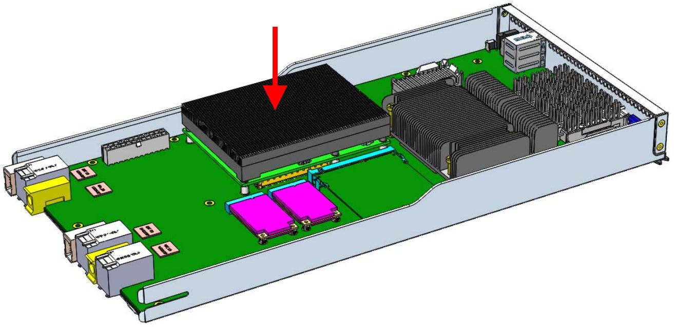
![3D CAD rendering of an internal electronic device chassis with labeled components and a red arrow indicating a specific area (no text or symbols present)](.mxn-4100-50-1z270-1000-10/bdb8363ca6626f6da418f174ea146c9ffb23d52942209368808f838fdfe38009.jpg)

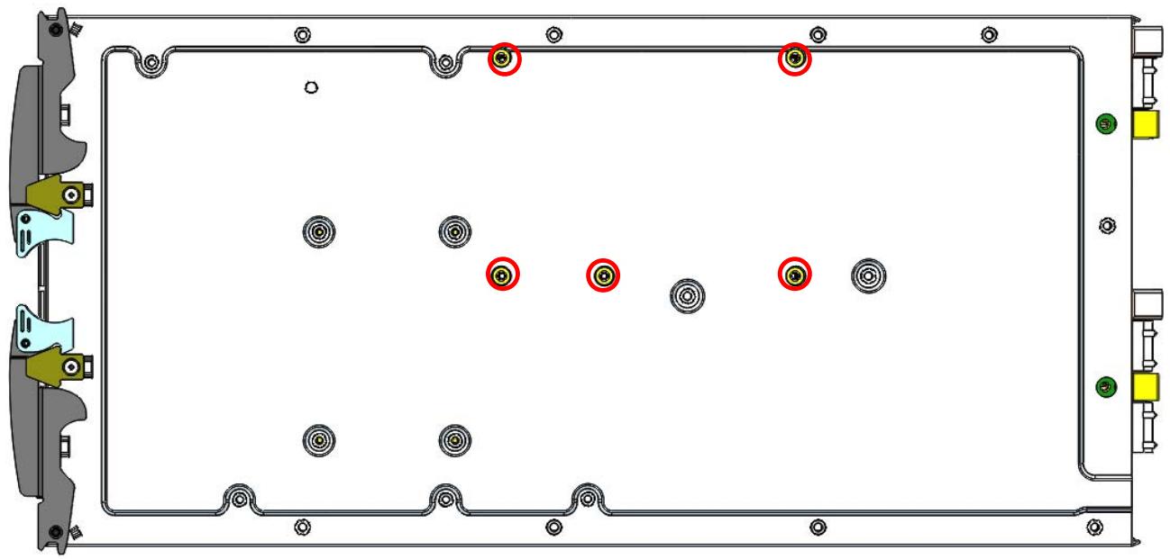
2. Secure the COMe module with 5 screws on bottom side. Do NOT over tighten the screws.
![Technical diagram of a rectangular device with internal components and mounting holes, no visible text or symbols](.mxn-4100-50-1z270-1000-10/f92c1f29766af1249372b2fb8be03b6e5a1349fb1ea6668db70acc85072a1a2f.jpg)

# 2.1.2 Installing an mSATA Module

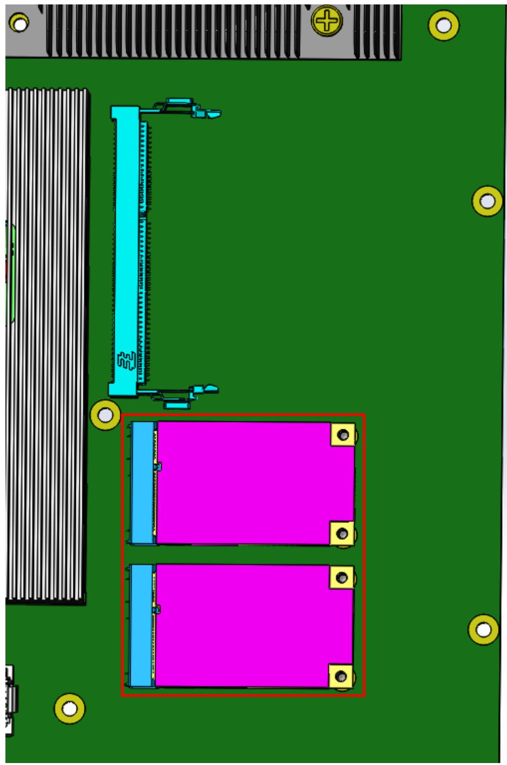
1. Insert an mSATA module into the onboard slot as shown.
2. Secure it to the board with 2 screws.
![Top-down view of a circuit board layout with two magenta rectangular panels and a blue vertical connector (no text or symbols visible)](.mxn-4100-50-1z270-1000-10/bc1a5ea9bca5a243cf58bc8d17ddf99671654171aaa83a657b4f9430a2eebfd7.jpg)

# 2.1.3 Installing a CMM Module

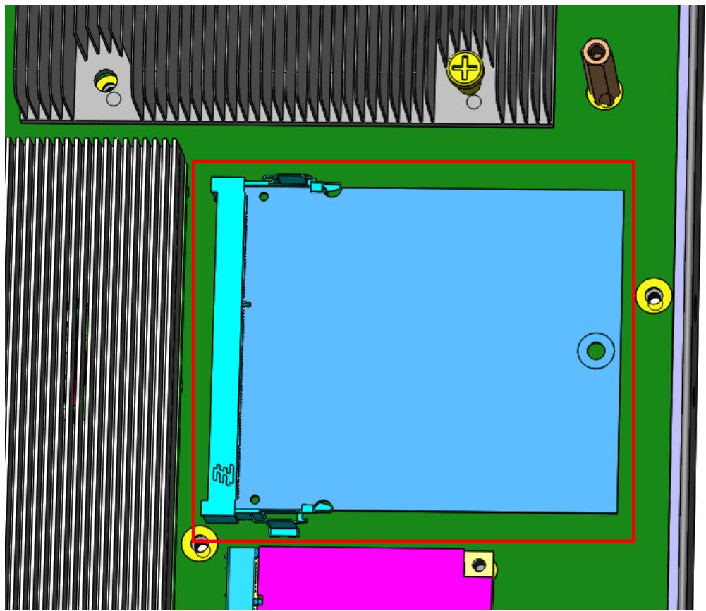
Insert a chassis management (CMM) module into the onboard slot as shown.
![3D CAD model of a computer monitor with visible circuit board, buttons, and mounting holes (no text or symbols)](.mxn-4100-50-1z270-1000-10/c48f545154241e5daa84fcdc2ed7579bea032ee9732f8ab6f302e9765c9e35e2.jpg)

# 2.1.4 Installing an I/O Expansion Module

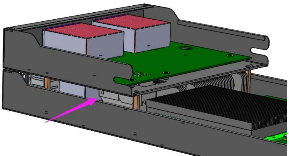
1. Press the I/O expansion module onto the board-to-board connectors on the MXN-4100 as shown.
![3D mechanical assembly diagram showing internal components with no visible text or symbols](.mxn-4100-50-1z270-1000-10/72e186aa016a93fac8509fede052541aabdcae76a15075d7b3884599246ea72f.jpg)

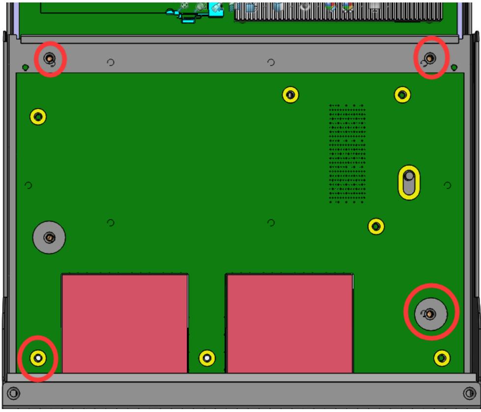
2. Secure the I/O expansion module with 4 screws as shown.
![Top-down view of a computer motherboard with green PCB and red components, marked with red circles and yellow connectors (no text or symbols)](.mxn-4100-50-1z270-1000-10/86dcbc2470d978966968f3dbe5772923efaada84b770e26dabe156a621d6be15.jpg)

# 2.2 Front Panel

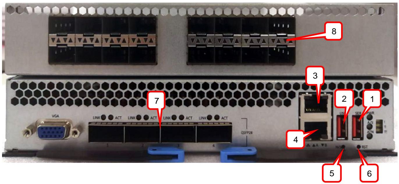
The MXN-4100 provides I/O connections from the front panel. There are two 1GbE RJ-45 LAN ports (top: COMe module, bottom: CMM), a total of 4x 100GbE QSFP28 ports, one USB 2.0 port and one USB serial port, as shown below.
![8\n3\n2 1\n4\n5 6\nVGA LINK ACT LINK ACT LINK ACT LINK ACT\nQSFP28\n1 2 3 4\nHUSB RST](.mxn-4100-50-1z270-1000-10/cd0302f70ea9f4c478a3a914e2bcdd6b5198ed11dd5488db1826445142ccb401.jpg)

<table><tr><td>I/O port</td><td>Description</td></tr><tr><td>1</td><td>Two-in-one USB serial console to COMe module and CMM (“SER”; baud rate: COMe module 115200, CMM 38400)</td></tr><tr><td>2</td><td>USB 2.0 (“USB”)</td></tr><tr><td>3</td><td>10/100/1000BASE-T RJ-45 port of COMe module (“A”)</td></tr><tr><td>4</td><td>10/100/1000BASE-T RJ-45 port of CMM (“B”)</td></tr><tr><td>5</td><td>Hot-swap button (“H/S”)</td></tr><tr><td>6</td><td>Reset button (“RST”)</td></tr><tr><td>7</td><td>MXN-4100: 4x 100G QSFP28 ports</td></tr><tr><td>8</td><td>NIM-1610: Switch I/O extension card with 16x 10G SFP+ (4x 40G QSFP optional)</td></tr></table>

# 2.3 Inserting and Removing the Switch Sled

Refer to the chapter Assembling the CSA-7400 of the CSA-7400 User’s Manual for instructions on inserting and removing the MXN-4100 Switch Sled.

# 3 Powering Up the Switch Sled

# 3.1 Power-Up Behavior

When power is supplied to the CSA-7400, all components will power up automatically. The behavior of the system when powered up is described below.

1. Cooling fans start speeding up as soon as power is applied to the system.
2. Power LEDs of both CPU and switch nodes turn ON (green).
3. CPU nodes start booting up: The status LED turns ON (red), indicating BIOS POST status. After BIOS POST is completed, the status LED changes from red to green, Indicating system status
Note: The BMC Watchdog timeout will turn off the status LED. If the BMC watchdog is not enabled, the green status LED will stay on.
4. After a few seconds, the switch node A/S LED turns ON (steady or blinking) indicating CM Active/Standby status.

# 3.2 Health/Status Indicators and Buttons

This section covers all of the LEDs on the MXN-4100 as show below.

![VGA\nLINK ● ACT LINK ● ACT LINK ● ACT LINK ● ACT\n1 2 3 4\nQSFP28\nUSB SER PWR\nACS\nATN\nH/S ● RST\nUSB SER\nPWR\nA/S\nATN\n1\n2\n3\n4\nH/S ● RST](.mxn-4100-50-1z270-1000-10/ee9c3a6fc27b3ab0f8806d69a3c8b7234a2e8b6cf0148dfa26d336b335f56245.jpg)

See the table below for LED descriptions.

<table><tr><td></td><td>LED #</td><td>Description</td></tr><tr><td rowspan="4">MXN-4100</td><td>1</td><td>Alarm LED: indicates CMM alarm level</td></tr><tr><td>2</td><td>Power LED (power on: Green)</td></tr><tr><td>3</td><td>Active/Standby (A/S) LED:Steady Green means CMM is activeBlinking Green means CMM is standby</td></tr><tr><td>4</td><td>ATN LED:Lights Green to indicate OK to hot-swap</td></tr></table>

# 4 Using the Switch Sled

On the CSA-7400 platform, the switch sleds are shipped with a pre-installed operating systems and the CPU sleds are shipped without a pre-installed operating system. This chapter covers how to run the MXN-4100’s operating system.

# 4.1 Login to the Switch System

The switch sled is shipped with an operating system pre-installed on the COMe module. Users can login to the system through the following modes.

• Via USB Serial Port
• Local login
Via Network Port

# 4.1.1 Login Via Serial Port

# Step 1

Connect a PC to the USB port labeled “SER” on the front panel of the MXN-4100 with a USB-to-USB cable.

![Front view of a server rack with hexagonal ventilation grilles, connected modules, and a highlighted internal component (no text or symbols visible)](.mxn-4100-50-1z270-1000-10/b57601efaebc777ef9c68e68c3deb10510b17033f280efd26f2144beff18992d.jpg)

# Step 2

Install the USB-serial chip driver “CDM v2.12.06 WHQL Certified.zip” or “CDM v2.12.06 WHQL Certified\_64.zip” on the PC. Check the COM number in the Device Manager.

![Device Manager\nFile Action View Help\nCN04128PC02\nBatteries\nBluetooth Radios\nComputer\nDisk drives\nDisplay adapters\nDVD/CD-ROM drives\nHuman Interface Devices\nIDE ATA/ATAPI controllers\nImaging devices\nKeyboards\nMemory technology driver\nMice and other pointing devices\nMonitors\nNetwork adapters\nPorts (COM & LPT)\nUSB Serial Port (COM6)\nUSB Serial Port (COM7)\nProcessors\nSound, video and game controllers\nSystem devices\nUniversal Serial Bus controllers](.mxn-4100-50-1z270-1000-10/27114cdd2217eac9a72bc5579919d4ad4d2cb49fe360fe69eb22706227c95507.jpg)

# Step 3

Open a serial port console tool (e.g. PuTTY), choose the COM port with the smaller number (if this port doesn’t work, try the other one), then set the baud rate to 115200. Power up the system and click the ‘Open’ button.

![PuTTY Configuration\nCategory:\nSession\nLogging\nTerminal\nKeyboard\nBell\nFeatures\nWindow\nAppearance\nBehaviour\nTranslation\nSelection\nColours\nConnection\nData\nProxy\nTelnet\nRlogin\nSSH\nSerial\nBasic options for your PuTTY session\nSpecify the destination you want to connect to\nSerial line\nSpeed\nCOM6\n115200\nConnection type:\nRaw Telnet Rlogin SSH Serial\nLoad, save or delete a stored session\nSaved Sessions\nDefault Settings\nLinux\ncom4\ncom5\nLoad\nSave\nDelete\nClose window on exit:\nAlways Never Only on clean exit\nAbout Open Cancel](.mxn-4100-50-1z270-1000-10/d7e74f0320c0f6a7790b2dbb8056e0903c31d94a0bccc6f42644dec1273ed927.jpg)

# Step 4

Input the user name “root” and password “adlink” to login to the system on the COMe module.

# 4.1.2 Local Login

The MXN-4100 COMe BIOS default setting does not enable the VGA display. Therefore, the first login to the MXN-4100 must be via the serial port: To enable local login using the VGA display:

1. Perform steps 1 to 3 of 4.1.1 Login Via Serial Port above. In step 3, click the “Open” button as soon as possible after powering on the system.
2. During the POST sequence, (when the screen begins receiving output), press the &lt;ESC&gt; or &lt;Del&gt; key to enter the BIOS setup.

![COM6 - PuTTY\nAptio Setup Utility - Copyright (C) 2012 American Megatrends, Inc.\nMain Advanced Boot Security Save & Exit\nSystem Information\nBIOS Version MXN-3610 0.92\nBuild Date and Time 06/13/2016 14:23:58\nProcessor Information\nIntel(R) Celeron(R) CPU 2002E @ 1.50GHz\nFrequency 1500 MHz\nProcessor ID 306c3\nStepping C0\nNumber of Processors 2Core(s) / 2Thread(s)\nGT Info GT1 (800 MHz)\nIGFX VBIOS Version B5B4\nTotal Memory 4096 MB (DDR3)\nPCH Information\nName LynxPoint\nPCH SKU HM86\nStepping 05/C2\nSystem Management\n(: Select Screen\n: Select Item\nEnter: Select\n+/-: Change Opt.\nF1: General Help\nF8: Previous Values\nF9: Optimized Defaults\nF10: Save & Exit\nESC: Exit\nVersion 2.15.1236. Copyright (C) 2012 American Megatrends, Inc.](.mxn-4100-50-1z270-1000-10/ee9b0ce7348a3b21059270c25a2a469a0df9528730340420985faa8d68e1b7cd.jpg)

To enable the VGA display, change the Boot > CSM parameters > Launch Video OpROM policy setting from “Do not launch” to “Legacy Only”. Save the settings and restart the system.

![Com6 - PuTTY\nAptio Setup Utility - Copyright (C) 2012 American Megatrends, Inc.\nBoot\nLaunch CSM	(Enabled)\nBoot option filter	(UEFI and Legacy)\nLaunch PXE OpROM poli	(Do not launch)\nLaunch Storage OpROM	(Legacy only)\nLaunch Video OpROM po	(Do not launch)\nControls the execution\nof UEFI and Legacy\nVideo OpROM\nOther PCI device RO	Launch Video OpROM policy\nDo not launch\nUEFI only\nLegacy only\nSelect Screen\nct Item\nEnter: Select\n+/-: Change Opt.\nF1: General Help\nF8: Previous Values\nF9: Optimized Defaults\nF10: Save & Exit\nESC: Exit\nVersion 2.15.1236. Copyright (C) 2012 American Megatrends, Inc.](.mxn-4100-50-1z270-1000-10/a1a1352e84dc03777613cb28a6f56814a9e01e714ba55e08698451e0e0b1681d.jpg)

Connect the MXN-4100 to a monitor using the VGA connector on the front panel. Login to the system on the COMe module with the user name “root” and password “adlink”.

# 4.1.3 Via Network Port

# Step 1

Connect the LAN port (“A”)of the COMe module to the DHCP server.

![Front view of a server rack with hexagonal network, ports, and connectors (no visible text or labels)](.mxn-4100-50-1z270-1000-10/0611cd20e26a3e26f3f4248a2285713af02f645264312c25707110f61bf10588.jpg)

# Step 2

Open an SSH tool (such as PuTTY) and input the host name “172.20.2.23” (you can login to the system on COMe module via serial port to confirm the IP address).

![PuTTY Configuration\nCategory:\nSession\nLogging\nTerminal\nKeyboard\nBell\nFeatures\nWindow\nAppearance\nBehaviour\nTranslation\nSelection\nColours\nConnection\nData\nProxy\nTelnet\nRlogin\nSSH\nSerial\nBasic options for your PuTTY session\nSpecify the destination you want to connect to\nHost Name (or IP address) Port\n172.20.2.23 22\nConnection type:\nRaw Telnet Rlogin SSH Serial\nLoad, save or delete a stored session\nSaved Sessions\nDefault Settings\nLinux\ncom4\ncom5\nLoad\nSave\nDelete\nClose window on exit:\nAlways Never Only on clean exit\nAbout Open Cancel](.mxn-4100-50-1z270-1000-10/5e7a4c7f038c5147e2dc3923d2106bb077fd5799d7cf35689b575f1afda5b59a.jpg)

# Step 3

Input the user name “root” and password “adlink” to login to the system on the COMe module.

# 4.2 Switch System IP Setup

Users can set the network to “DHCP” or “Static” mode by logging into the switch system via serial console and editing “/etc/sysconfig/network-scripts/ifcfg-enp2s0”. The default mode is “DHCP”.

After editing, save the change, and run “reboot” for the change to take effect.

![root@localhost:~\nTYPE='Ethernet'\nBOOTPROTO='dhcp'\nDEFROUTE='yes'\nPEERDNS='yes'\nPEERROUTES='yes'\nIPV4_FAILURE_FATAL='no'\nIPV6INIT='yes'\nIPV6_AUTOCONF='yes'\nIPV6_DEFROUTE='yes'\nIPV6_PEERDNS='yes'\nIPV6_PEERROUTES='yes'\nIPV6_FAILURE_FATAL='no'\nNAME='enp2s0'\nUUID='6aa2084c-9b00-41a3-9536-de9465973b7e'\nDEVICE='enp2s0'\nONBOOT='yes'\n~/etc/sysconfig/network-scripts/ifcfg-enp2s0' 16L, 310C](.mxn-4100-50-1z270-1000-10/063b9784cafbf1c7ea90668c2a1b3b182f8e756ab1c5845d1ea5bf8dac48c400.jpg)

# 4.3 COMe OS Version Check

After logging in to the switch system, you can check OS version by using the following command:

uname –a or cat /proc/version

The shipped system version is CentOS 7 (Linux kernel 3.10.0-229.e17.x86\_64), as shown below.

![(root@localhost ~)# uname -a\nLinux localhost.localdomain 3.10.0-229.el7.x86_64 #1 SMP Fri Mar 6 11:36:42 UTC\n2015 x86_64 x86_64 x86_64 GNU/Linux\n(root@localhost ~)# cat /proc/version\nLinux version 3.10.0-229.el7.x86_64 (builder@kbuilder.dev.centos.org) (gcc versi\non 4.8.2 20140120 (Red Hat 4.8.2-16) (GCC) ) #1 SMP Fri Mar 6 11:36:42 UTC 2015\n(root@localhost ~)#](.mxn-4100-50-1z270-1000-10/17e0eaf5dedcc7b5659dac93cb57901becdcef444676010cf663febca6cf5125.jpg)

# 4.4 PacketManager on the Switch Sled

ADLINK PacketManager runs on the switch system COMe module under Linux OS. It includes the most commonly used Layer2/3 stacks and switch management features.

The following sub-sections describe how to check the version, enter Configure Mode and get help.

# 4.4.1 Check PacketManager Installation Version

Go to the Linux file path “/root” to check the PacketManager version. The file “PacketManager\_xxx\_Vxx\_s.xxx.tar.gz” is the software installation package. The package will be unzipped to the directory “PacketManager\_xxx\_Vxx\_s.xxx”.

![login as: root\nroot@172.20.2.23's password:\nLast login: Tue Jun 6 13:17:14 2017 from 172.20.2.12\n(root@localhost ~)# ls -lt\ntotal 32044\ndrwxr-xr-x 12 root root 4096 Jun 6 13:29 PacketManager_7400_V1.0_s.665\n-rwxr-xr-x 1 root root 32789363 Jun 6 13:27 PacketManager_7400_V1.0_s.665.tar\n.gz\n-rwxr-xr-x 1 root root 408 Sep 30 2016 preset.sh\n-rwxr-xr-x. 1 root root 1171 Aug 12 2016 read.sh\n-rwxr-xr-x. 1 root root 110 Aug 10 2016 update.sh\ndrwxr-xr-x. 2 root root 98 May 30 2016 Pictures\ndrwxr-xr-x. 2 root root 6 May 27 2016 Desktop\ndrwxr-xr-x. 2 root root 6 May 20 2016 Music\ndrwxr-xr-x. 2 root root 6 May 20 2016 Videos\ndrwxr-xr-x. 2 root root 6 May 20 2016 Documents\ndrwxr-xr-x. 2 root root 6 May 20 2016 Downloads\ndrwxr-xr-x. 2 root root 6 May 20 2016 Public\ndrwxr-xr-x. 2 root root 6 May 20 2016 Templates\ndrwxr-xr-x. 2 root root 6 May 19 2016 perl5\n-rw----. 1 root root 1463 May 19 2016 anaconda-ks.cfg\n(root@localhost ~)#](.mxn-4100-50-1z270-1000-10/70af33b440ea04c06e3562d7391c8e17621d90896d4e7d0719cbcc500efc3783.jpg)

The PacketManager version number consists of three parts: “7400” represents the platform, “V1.0” is the major version number, and “S.665” is the secondary version number.

# 4.4.2 Command Line Interface and Configure Mode

# Step 1

After logging into the switch system, you can input the following command to enter the command line interface (CLI):

telnet localhost 9896

# Step 2

To enter Configure Mode, use the enable command “en” or “enable” and default password “adlink”. The display will not echo the password. After entering Configure Mode successfully, the prompt will change from ">" to "#", as show below.

![COM6 - PuTTY\nCentOS Linux 7 (Core)\nKernel 3.10.0-229.el7.x86_64 on an x86_64\n\nlocalhost login: root\nPassword:\nLast login: Wed Jan 21 06:51:12 on ttyS0\n(root@localhost ~)# telnet localhost 9896\nTrying 127.0.0.1...\nConnected to localhost.\nEscape character is '^)'.\n**********************************************************************\n* Copyright(c) 2012 ADLINK Technology. Inc. All rights reserved. *\n*\n* Build On May 27 2017, 16:33:04 *\n**********************************************************************\nADLINK) en\nPassword:\nADLINK#\nADLINK#\nADLINK#\nADLINK#\nADLINK#\nADLINK#](.mxn-4100-50-1z270-1000-10/6b5351e9007834a5d0aa4675d76d026a720ade1b5d946868232435f2faf0ca2a.jpg)

# 4.4.3 Get Help and Check Version

Entering a question mark “?” at the system prompt will display a list of commands or sub commands available for the current command mode. You can also type a “?” in the middle of a command line to view the list of valid arguments or parameters needed to complete the command.

![Connected to localhost.\nEscape character is '^)'.\n**********************************************************************\n* Copyright(c) 2012 ADLINK Technology. Inc. All rights reserved. *\n*\n* Build On Jan 20 2017, 14:33:20\n**********************************************************************\nADLINK) en\nPassword:\nADLINK#\nbase Enter into Base chip config mode\ncmm Enter into cmm mode\ndelete delete\nexit Exit current mode and down to previous mode\nexport export\nfabric Enter into Fabric chip config mode\nimport import configure file\npassword Assign the privileged level password\nrestore Reset start-up configuration to factory default. Never try unless you know the meaning!\nshow Show running system information\nwho Display who is on vty\nwrite Write running configuration to start-up configuration file\nADLINK#](.mxn-4100-50-1z270-1000-10/69006977dec5ca4c6db7d214548635907ee8e6c27a6a5770644952f6821c14cb.jpg)

You can also enter “command&lt;space&gt;?” to get help for a specific command, such as “show $\ ?$ .

![(root@localhost ~)# telnet localhost 9896\nTrying 127.0.0.1...\nConnected to localhost.\nEscape character is '^)'.\n**************************\n* Copyright(c) 2012 ADLINK Technology. Inc. All rights reserved. *\n*\n* Build On Jan 20 2017, 14:33:20\n**************************\nADLINK) en\nPassword:\nADLINK# show\nhistory Display the session command history\nrunning-config running configuration\nstartup-config Contentes of startup configuration\nsystem Displays brief system information\nversion Displays the version information\nADLINK# show](.mxn-4100-50-1z270-1000-10/73f3f83ee8adb7912f6828484431977990c3d38e1bdda09218c9b18f913b9ee0.jpg)

Use the “show version” command to check the OS and SDK versions.

![ADLINK# show version\nOS version : Linux localhost.localdomain 3.10.0-229.el7.x86_64 #1\nSMP Fri Mar 6 11:36:42 UTC 2015 x86_64 x86_64 x86_64 GNU/Linux\n\nDevice Revision : 1\n\nFirmware Revision : 3.00\n\nIPMI Version : 2.0\n\nADLINK sdk Version : PacketManager_7400_V1.0_s.665\n\nSupport Board : CAS-7400\nBuild on : May 27 2017 16:33:04\nCopyright 2012-2013, ADLINK TECHNOLOGY Inc.\nADLINK#\nADLINK#\nADLINK#\nADLINK#\nADLINK#\nADLINK#\nADLINK#](.mxn-4100-50-1z270-1000-10/55834a01287b9a9c769f009edcfd6ea4e5953a9335ff0f009c73e90dad248898.jpg)

# 4.5 Fabric Mode

At the system prompt, enter the command “fabric” to enter fabric mode:

![ADLINK# fab\nADLINK# fabric\nADLINK(fabric)#\nacl acl\nclear Clear functions\nexit Exit current mode and down to previous mode\nigmp-proxy IGMP proxy sub-system\nigmp-snooping IGMP Snooping command\nip IP information\n12 Layer-2 subsystem\nlbg Operation for load-balancing group feature\nlldp lldp command\nno Negate a command or set its defaults\nping send count echo messages\nport Port subsystem\nquit Leave switch manager shell\nroute route\nshow Show running system information\nspanning-tree spanning tree\ntrunk operation about trunk configuration.\nvlan VLAN subsystem\nvrrp vrrp configuration\nwrite Write running configuration to start-up configuration file\nADLINK(fabric)#](.mxn-4100-50-1z270-1000-10/394c0ffd8e24cfcca0877a8160e30a18d24186b64984a62b87e06a36b2915bd8.jpg)

In fabric mode, you can configure the switch. An example command is “show port” which can be used to check the port list. For detailed information about configuration commands, please refer to the ADLINK PacketManager Configuration Guide.

![ADLINK) en\nPassword:\nADLINK# fa\nADLINK# fabric\nADLINK(fabric)# show port\nPORT  LINK  SPEED  DUPLEX  AUTONEG  STP-STATE  PAUSE  MTU\n----+----+----+----+----+----+----\nxe1  up    100G  full  Yes  Forward  TX RX 1536\nxe2  down   OM    full  No  Forward  TX RX 1536\nxe3  down   OM    full  No  Forward  TX RX 1536\nxe4  down   OM    full  No  Forward  TX RX 1536\nxe5  down   OM    full  No  Forward  TX RX 1536\nxe6  down   OM    full  No  Forward  TX RX 1536\nxe7  down   OM    full  No  Forward  TX RX 1536\nxe8  down   OM    full  No  Forward  TX RX 1536\nxe9  up    100G  full  Yes  Forward  TX RX 1536\nxe10  down   OM    full  No  Forward  TX RX 1536\nxe11  down   OM    full  No  Forward  TX RX 1536\nxe12  down   OM    full  No  Forward  TX RX 1536\nxe13  down   OM    full  No  Forward  TX RX 1536\nxe14  down   OM    full  No  Forward  TX RX 1536\nxe15  down   OM    full  No  Forward  TX RX 1536\nxe16  down   OM    full  No  Forward  TX RX 1536\nxe17  down   OM    full  No  Forward  TX RX 1536\nxe18  down   OM    full  No  Forward  TX RX 1536\nxe19  down   OM    full  No  Forward  TX RX 1536\nxe20  down   OM    full  No  Forward  TX RX 1536\nxe21  down   OM    full  No  Forward  TX RX 1536\nxe22  down   OM    full  No  Forward  TX RX 1536\nxe23  down   OM    full  No  Forward  TX RX 1536\nxe24  down   OM    full  No  Forward  TX RX 1536\nxe25  down   OM    full  No  Forward  TX RX 1536\nxe26  down   OM    full  No  Forward  TX RX 1536\nxe27  down   OM    full  No  Forward  TX RX 1536\nxe28  down   OM    full  No  Forward  TX RX 1536\nxe29  down   OM    full  No  Forward  TX RX 1536\nxe30  down   OM    full  No  Forward  TX RX 1536\nxe31  down   OM    full  No  Forward  TX RX 1536\nxe32  down   OM    full  No  Forward  TX RX 1536\nxe33  down   OM    full  No  Forward  TX RX 1536\nxe34  down   OM    full  No  Forward  TX RX 1536\nxe35   down   OM    full  No(fcel)ADLINK (fabric) #](.mxn-4100-50-1z270-1000-10/0ec4cb572234c486edcb89653be7faeac65d244e38761bc073b712f97181733d.jpg)

# 5 Maintenance

# 5.1 Hot-Swapping the Switch Sled

When hot-swapping the switch sled, the user must first push the hot-swap (H/S) button at the lower right of the front panel, and wait until the ATN LED turns on before removing the switch sled from the chassis.

![ATN LED](.mxn-4100-50-1z270-1000-10/fc3beb33e934a50d245c23ad4c2398dd0966d946116646ee3e97e1e8b4872aa9.jpg)

A detailed description of the hot-swap process is outlined below:

When the H/S button is pushed, the signal is replicated by a logic module on the mid plane and sent to the four CPU sleds. At the same time, a graceful shutdown of the COMe module is triggered by briefly pulling the COMe PWR\_BTN GPIO high, emulating a user to push the power button.
When the CPU sled detects the H/S signal, it will perform a PCIe device removal on CPU sled based on the PCIe hot-swap specification. When the CPU sled finishes this task, it asserts its ATN LED line.
After the logic module on the midplane detects that all ATN LED lines are asserted and the COMe module S5 signal is also asserted, it will turn on the ATN LED on the switch front panel.

# 5.2 Updating the Switch System BIOS

Users can use the Intel Flash Programming Tool (FPT) to update the system BIOS on the COMe module, including Intel Management Engine (ME), while preserving the MAC address of the internal NIC on the PCH of the COMe module.

1. Boot to DOS
2. Flash BIOS (not including ME) command: fpt -f xxx.rom –bios
3. Flash BIOS (including ME) command: fpt -f xxx.bin –savemac

# Safety Instructions

For user safety, please read and follow all instructions, WARNINGS, CAUTIONS, and NOTES marked in this manual and on the associated equipment before handling/operating the equipment.

1. Read these safety instructions carefully.
2. Keep this user’s manual for future reference.
3. Read the specifications section of this manual for detailed information on the operating environment of this equipment.
4. The equipment can be operated at an ambient temperature of $4 0 ^ { \circ } \mathsf { C }$
5. When installing/mounting or uninstalling/removing equipment; or when removal of the chassis lid required for user servicing (Section 3.1-3.5):
• Turn off power and unplug any power cords/cables, and
• Reinstall the chassis lid before restoring power.

6. To avoid electrical shock and/or damage to equipment:

• Keep equipment away from water or liquid sources;
• Keep equipment away from high heat or high humidity;
• Keep equipment properly ventilated (do not block or cover ventilation openings);
• Make sure to use recommended voltage and power source settings;
Always install and operate equipment near an easily accessible electrical socketoutlet;
• Secure the power cord (do not place any object on/over the power cord);
Only install/attach and operate equipment on stable surfaces and/or recommended mountings;
If the equipment will not be used for long periods of time, turn off and unplug the equipment from its power source.

7. Never attempt to fix the equipment. Equipment should only be serviced by qualified personnel.

8. A Lithium-type battery may be provided for uninterrupted, backup or emergency power.

CAUTION! Risk of explosion if battery is replaced with one of an incorrect type. Please dispose of used batteries appropriately.

9. Equipment must be serviced by authorized technicians when:

• The power cord or plug is damaged;
Liquid has penetrated the equipment;
It has been exposed to high humidity/moisture;
• It is not functioning or does not function according to the user’s manual;
• It has been dropped and/or damaged; and/or,
• It has an obvious sign of breakage.

10. Please pay strict attention to all warnings and advisories appearing on the device, to avoid injury or damage.

11. The equipment may have more than one power supply input. To reduce the risk of electrical shock, trained personnel should disconnect all power supply inputs before servicing.

CAUTION! Disconnect all power supply inputs before servicing.

12. It is recommended that equipment be installed only in a server room or computer room where access is:

Restricted to qualified service personnel or users familiar with restrictions applied to the location, reasons therefor, and any precautions required;
Only afforded by the use of a tool or lock and key, or other means of security, and is controlled by the authority responsible for the location.

# Consignes de Sécurité Importantes

Pour assurer la sécurité de l’utilisateur, veuillez lire et suivre toutes les directives, ainsi que les AVERTISSEMENTS, MISES EN GARDE et REMARQUES de ce manuel et indiqués sur l’équipement associé avant de manipuler ou utiliser l’équipement.

1. Veuillez lire attentivement ces instructions de sécurité avec soin.
2. Veuillez conserver ce manuel pour référence future.
3. Veuillez lire la section des spécifications de ce manuel pour avoir des informations détaillées sur l’environnement d’exploitation de cet équipement.
4. L’équipement peut être utilisé à une température ambiante de 40 °C.
5. Lors de l’installation ou du montage et de la désinstallation ou de la dépose de l’équipement; ou lors de la dépose du couvercle du châssis pour procéder à l’entretien par l’utilisateur (Sections 3.1-3.5):

• Coupez l’alimentation et débranchez les cordons et les câbles d’alimentation, et
• Reposez le couvercle du châssis avant de remettre l’alimentation.

6. Pour éviter un risque d’électrocution et pour éviter d’endommager l’équipement :

• Éloignez l’équipement de l’eau et de toute source liquide;
Éloignez l’équipement de toute source de chaleur ou d’humidité élevée;
Gardez l’équipement correctement ventilé (ne pas bloquer ou couvrir les ouvertures de ventilation);
Veillez à utiliser la tension recommandée et les réglages adéquats pour la source d’alimentation;
• Veuillez toujours installer et exploiter l’équipement à proximité d’une prise de courant facilement accessible;
Assurez-vous que le cordon d’alimentation est acheminé de manière sécuritaire (ne déposez aucun objet dessus);
Installez, fixez et utilisez l’équipement sur des surfaces stables ou sur les fixations recommandées uniquement;
Si l’équipement n’est pas utilisé pendant une longue période, éteignez-le et débranchez-le de sa source d’alimentation.

7. N’essayez jamais de réparer l’équipement. L’équipement ne doit être réparé que par du personnel qualifié.

8. Une pile au lithium peut être installée pour assurer l’alimentation de secours ou d’urgence en continu.

ATTENTION! Risque d’explosion si la pile est remplacée par une autre de type incorrect. Veuillez jeter les piles usagées de façon appropriée.

9. L’équipement doit être entretenu par des techniciens agréés lorsque :

le cordon d’alimentation est endommagé ou lorsque la fiche électrique est endommagée;
du liquide a pénétré à l’intérieur de l’équipement;
• l’équipement a été exposé à un taux d’humidité élevé;
• l’équipement ne fonctionne pas ou ne fonctionne pas conformément au manuel de l’utilisateur;
• l’équipement est tombé ou lorsqu’il a été endommagé;
• l’équipement présente un signe évident de défaillance.

10. Veuillez porter une attention rigoureuse à tous les avertissements et à tous les avis figurant sur l’appareil, pour éviter des blessures ou des dommages.

11.ATTENTION! L’équipement peut avoir plus d’une entrée d’alimentation. Pour réduire le\` risque d’électrocution, le personnel qualifié devrait déconnecter toutes les entrées d’alimentation avant de procéder à l’entretien.
12.Il est recommandé que l'équipement soit installé que dans une salle de serveur ou de la salle informatique où:

L'accès est limité au personnel de maintenance qualifié ou utilisateurs familiers avec les restrictions appliquées à l'emplacement, motifs, et tout les précautions nécessaires, et;

L'accès est uniquement assurée par l'utilisation d'un outil ou clé, ou d'autres moyens de sécurité, et est contrôlé par l'autorité responsable de l'emplacement.

51.06 pt

# Getting Service

Ask an Expert: http://askanexpert.adlinktech.com

# ADLINK Technology, Inc.

Address: 9F, No.166 Jian Yi Road, Zhonghe District

New Taipei City 235, Taiwan

新北市中和區建一路 166 號 9 樓

Tel: +886-2-8226-5877

Fax: +886-2-8226-5717

Email: service@adlinktech.com

# Ampro ADLINK Technology, Inc.

Address: 5215 Hellyer Avenue, #110, San Jose, CA 95138, USA

Tel: +1-408-360-0200

Toll Free: +1-800-966-5200 (USA only)

Fax: +1-408-360-0222

Email: info@adlinktech.com

# ADLINK Technology (China) Co., Ltd.

Address: 上海市浦东新区张江高科技园区芳春路 300 号 (201203)

300 Fang Chun Rd., Zhangjiang Hi-Tech Park, Pudong New Area

Shanghai, 201203 China

Tel: +86-21-5132-8988

Fax: +86-21-5132-3588

Email: market@adlinktech.com

# ADLINK Technology GmbH

Address: Hans-Thoma-Strasse 11, D-68163, Mannheim, Germany

Tel: +49-621-43214-0

Fax: +49-621 43214-30

Email: emea@adlinktech.com

Please visit the Contact page at www.adlinktech.com for information on how to contact the ADLINK regional office nearest you.
[🔗 Link to the original document](.mxn-4100-50-1z270-1000-10/mxn-4100-50-1z270-1000-10.pdf)