# COM Express

nanoX Starter Kit

Quick Start Guide

![ADLINK\nTECHNOLOGY INC.\nnanoX\nStarter Kit\nCOM Express\nwww.adlinktech.com\nEverything you need to start your own\ncarrier board design\n• Ultra size COM Express module\n• Evaluation Carrier with all cabling\n• Power Supply,Thermal Solution\n• Reference Schematics, Layout, Mechanical files\n• COM Express Carrier Design Guide\nCOM +Express Ultra size: 84 x 55 mm\nSmall Size,\nBig Potential](.nanox-starterkit-50-1j032-1010-201/e9e9ac6f9620fd54ab9c77c28455a031b5eecbef72d71aceed30cbd09a59b645.jpg)

Manual Revision: 2.01

Revision Date: July 11, 2012

Part Number: 50-1J032-1010

# Revision History

<table><tr><td>Revision</td><td>Date</td><td>Changes</td></tr><tr><td>2.00</td><td>2010/11/25</td><td>Initial Release</td></tr><tr><td>2.01</td><td>2012/07/11</td><td>Add support for Type 10 modules (PCB rev. A2)</td></tr></table>

# Preface

# Copyright 2010-12 ADLINK Technology Inc.

This document contains proprietary information protected by copyright. All rights are reserved. No part of this manual may be reproduced by any mechanical, electronic, or other means in any form without prior written permission of the manufacturer.

# Disclaimer

The information in this document is subject to change without prior notice in order to improve reliability, design, and function and does not represent a commitment on the part of the manufacturer.

In no event will the manufacturer be liable for direct, indirect, special, incidental, or consequential damages arising out of the use or inability to use the product or documentation, even if advised of the possibility of such damages.

# Trademarks

AMIBIOS®8 is a registered trademark of American Megatrends, Inc. COM Express™ is a trademark of the PCI Industrial Computer Manufacturers Group (PICMG). Product names mentioned herein are used for identification purposes only and may be trademarks and/or registered trademarks of their respective companies.

# Quality Standards

ADLINK is certified to be in conformance with ISO 9001 quality management and ISO-14001 environmental management systems, and has addtional TL 9000 certification to meet the supply chain quality requirements of the global communications industry.

# Environmental Responsibility (RoHS & WEEE)

ADLINK is committed to fulfill its social responsibility to global environmental preservation through compliance with the European Union's Restriction of Hazardous Substances (RoHS) directive and Waste Electrical and Electronic Equipment (WEEE) directive. Environmental protection is a top priority for ADLINK. We have enforced measures to ensure that our products, manufacturing processes, components, and raw materials have as little impact on the environment as possible. When products are at their end of life, our customers are encouraged to dispose of them in accordance with the product disposal and/or recovery programs prescribed by their nation or company.

# Electrostatic Sensitive Device (ESD)

![The image displays a yellow square background featuring a black graphic symbol in the center. The symbol is composed of three black triangles arranged to form a larger triangular shape: one triangle is positioned at the top center, and two triangles are at the bottom, one on the left and one on the right. Inside the bottom-left black triangle, there is a white silhouette that resembles a stick figure of a person or animal. There is no text present in the image.](.nanox-starterkit-50-1j032-1010-201/2645922b9f27891069305ce7140aa7729a2e37e0d73ee37adabde8ed1c9a3b9c.jpg)

Always ground yourself to remove any static charge before touching the module or carrier board. Modern electronic devices are very sensitive to static electric charges. Use a grounding wrist strap at all times. Place all electronic components on a static-dissipative surface or in a static-shielded bag when they are not installed in a chassis.

# Conventions

Take note of the following conventions used throughout this manual to make sure that tasks and instructions are performed properly.

![The image displays a white document icon with a folded top-right corner and horizontal lines suggesting text. A large, bold red checkmark is superimposed over the center of the document.](.nanox-starterkit-50-1j032-1010-201/db792fd8ac73e8221f148a9e3ccbb3c28643cac96cb4a4c172c548bf4d2781ee.jpg)
NOTE:

Additional information, aids, and tips that help perform specific tasks.

![The image shows a yellow triangular warning sign with a thick black border. In the center of the triangle is a large black exclamation point.](.nanox-starterkit-50-1j032-1010-201/106c0d848b418feaef13f5b525ead88c6d071436795a91fc4777e2a809fc392a.jpg)
CAUTION:

Critical information that users MUST know and instructions that users MUST perform to complete a task.

![The image displays a red equilateral triangle with a white exclamation mark centered inside it.](.nanox-starterkit-50-1j032-1010-201/1936a1da8d3f10ddeb419ccaf6a29b21b0eb3724a3267e12bacc9fdad0493484.jpg)
WARNING:

Information to prevent physical injury, data loss, component damage, program corruption, etc. when trying to complete a specific task.

This page intentionally left blank.

# Table of Contents

# Preface . 3

# Table of Contents..

# Introduction ... 9

1.1 Overview ... 9

1.2 How to order the nanoX Starter Kit .. 9

1.3 What's included in the nanoX Starter Kit? .. 10

# 2 Getting Started .. . 14

2.1 Unpacking. 14

2.2 Type 1 Module Installation . 16

2.3 Type 10 Module Installation ........... 21

DVI Display Interface Installation .. . 26

2.4.. . 26

2.5 LVDS Output using HannStar Flat Panel Display.......... . 27

2.6 Power and I/O Connections ....... . 30

2.7 Powering Up the nanoX-BASE System.. 32

# 3 Using a TTL Flat Panel Display . . 33

3.1 Overview ........... . 33

3.2 Connectors and Jumpers ............. . 34

3.3 Installation .. . 39

# Technical Support .... . 42

This page intentionally left blank.

# 1 Introduction

# 1.1 Overview

The nanoX Starter Kit is intended for testing and verification of COM Express systems based on Type 1 and Type 10 modules and complies with the PICMG® COM.0 R1.0 and R2.0 specification. It includes everything customers need to begin their own design and development.

The nanoX Starter Kit includes the nanoX-BASE standard ATX size COM Express reference carrier board, a Mini size COM Express module of your choice, and additional items such as cabling, power supply and thermal solution. The complete kit allows customers to quickly emulate the functionality of their end product for software development and hardware verification. Drivers, BSPs, design files (including schematics, mechanical drawings and BOM), certificates and test reports are included to assist customers in designing their own custom carrier board. The nanoX Starter Kit also includes additional development tools including a verified 10.1" LVDS flat panel display, an LVDS-to-TTL conversion board, and ADD2 DVI card.

# 1.2 How to order the nanoX Starter Kit

![The flowchart displays a linear, three-step process arranged vertically with downward-pointing arrows connecting the blocks.\n\n**Labeled Blocks:**\n*   **Top Block:** 'Select a core module and thermal solution according to your needs'\n*   **Middle Block:** 'Contact an ADLINK sales representative in your region'\n*   **Bottom Block:** 'Get the specific part number for your nanoX Starter Kit'\n\n**Connections:**\n*   A downward arrow connects the top block to the middle block.\n*   A downward arrow connects the middle block to the bottom block.](.nanox-starterkit-50-1j032-1010-201/51c91927041dadc46d9e63e500ae5e8348adbd8db9340c82a69f5dabd752948e.jpg)

# 1.3 What's included in the nanoX Starter Kit?

Standard Items

<table><tr><td>No.</td><td colspan="2">Photo</td><td>ADLINK P/N</td><td>Item Description</td></tr><tr><td>1</td><td colspan="2">&lt;img src="images/c3d7ab4247447ad590292d96fd9da230589693cd18f780fe51b686debe7808d6.jpg"/&gt;</td><td>91-77102-0010</td><td>nanoX-BASE Reference Carrier Board</td></tr><tr><td>2</td><td colspan="2">&lt;img src="images/45d6b95e760a6b0e467b8ab067bb29c30529f09496ee413c7a1498991496d8ad.jpg"/&gt;</td><td>29-90100-F000</td><td>10.1&quot; LVDS flat panel display (1024 x 600) HSD100IFW1-A00</td></tr><tr><td>3</td><td colspan="2">&lt;img src="images/70c113570a71f189a0fce3d5244834f6f2ac62466455aab617bfb245ec11960f.jpg"/&gt;</td><td>91-79203-0010</td><td>Flat Panel Transfer Board for LVDS to TTL signal conversion</td></tr><tr><td>4</td><td colspan="2">&lt;img src="images/163ece0d6aeb1ffacc29a46ed81ce4fb4e2159e9932659b55917b55954ef9bf7.jpg"/&gt;</td><td>92-94046-0010</td><td>ADD2 DVI Adapter card (FI-CH7307)</td></tr><tr><td>5</td><td colspan="2">&lt;img src="images/2b7e4b2ade88972344d459aece57ee5ec2dfccc602d268c479b0d25cb55a4534.jpg"/&gt;</td><td>29-024L0-0010.</td><td>USB flash drive</td></tr><tr><td>6</td><td colspan="2">&lt;img src="images/30e39e30e30e6552735e3b4ed550b7263502a1e98a5451adcedc144e0aa9810b.jpg"/&gt;</td><td>31-32210-1000</td><td>Power supply</td></tr></table>

Standard Cabling

<table><tr><td>Photo</td><td>Part No.</td><td>Item Description</td></tr><tr><td>&lt;img src="images/2981f86d77a6ee3d76de434a6bc081efa9f11fe50664afd0425b73d19b122275.jpg"/&gt;</td><td>30-20243-2000</td><td>LVDS panel cable</td></tr><tr><td>&lt;img src="images/57e58f6918926023d36994467c738ce795a541518e4fafaf96996969cfc78af8.jpg"/&gt;</td><td>30-20449-0000</td><td>FPTB LVDS-to-LVDS cable</td></tr><tr><td>&lt;img src="images/616728d082e1f2a2e3c4dda24e7f31dfcd7076db421eea72f995f33e4fed5e31.jpg"/&gt;</td><td>30-30012-0000</td><td>SDVO flat cable</td></tr><tr><td>&lt;img src="images/3a8e73ffd9b74f4f1e0617bfb734d6712e17ff5eb26194b34947487d82fe5a05.jpg"/&gt;</td><td>30-10057-5010</td><td>7P SATA cable</td></tr><tr><td>&lt;img src="images/595b4999d605aab3d8499d632538a4e1597b7a404f7744e15c12ace45fa8423d.jpg"/&gt;</td><td>30-20171-1000</td><td>4-pin Molex to 2x SATA Power cable</td></tr><tr><td>&lt;img src="images/ce5a3263c5942edb8b8b832fc9f1050099065d01ce0b651220c10844363e55c7.jpg"/&gt;</td><td>30-01068-0000</td><td>USB 2.0 Type A to mini-B cable 2m</td></tr><tr><td>&lt;img src="images/18942ce4e13d3ba1449c2d58cfcf26fb5f3d25df1ee32615985a1eca12cf5686.jpg"/&gt;</td><td>30-10014-3000</td><td>LPT Flat cable IDC to DB25, L=215mm</td></tr><tr><td>&lt;img src="images/ff19ab21d6d083507c1641b41b16feb9729e55daf2a83ae9e14f2f6e2e08c460.jpg"/&gt;</td><td>30-20027-3000</td><td>PSU converter cable for AT mode using ATX power supply (no 5Vsb)</td></tr><tr><td>&lt;img src="images/f036d871333518306a318ffbb82ba995eba71376e95008e02956f7856145ff88.jpg"/&gt;</td><td>30-00001-0030</td><td>US Power Cord 10A,125V</td></tr><tr><td>&lt;img src="images/23e09c9cdbe3c09c825652406b79d2a0a53e13ac50571e95ed17a6ab3e0329a7.jpg"/&gt;</td><td>30-00002-0010</td><td>EU Power Cord 220V</td></tr></table>

Optional Items

<table><tr><td colspan="3">Type 1 Modules</td></tr><tr><td>Photo</td><td>Part No.</td><td>Item Description</td></tr><tr><td rowspan="4">&lt;img src="images/bcde96af4a2fbe3705c121715765845223722de9bc744af30495114f99500cb6.jpg"/&gt;</td><td>91-72301-1030</td><td>nanoX-ML-53-512(G)Mini size COM Express Type 1 Module with Intel Atom Processor Z530 at 1.6GHz, 512 MB memory</td></tr><tr><td>91-72301-1130</td><td>nanoX-ML-53-512/4G(G)Mini size COM Express Type 1 Module with Intel Atom Processor Z530 at 1.6GHz, 512 MB memory and 4 GB SSD</td></tr><tr><td>91-72301-3130</td><td>nanoX-ML-51-512/4G(G)Mini size COM Express Type 1 Module with Intel Atom Processor Z510 at 1.1GHz, 512 MB memory and 4 GB SSD</td></tr><tr><td>91-72301-4030</td><td>nanoX-ML-53P-512/4G(G)Mini size COM Express Type 1 Module with Intel Atom Processor Z530 at 1.6GHz, 512 MB memory, 4 GB SSD and 2 PCIe x1</td></tr><tr><td>&lt;img src="images/330dbab254ec6fb4adc1f9c45d825f120311600a3bc6228fc53eb60139b572f4.jpg"/&gt;</td><td>91-95041-1010</td><td>THS-nML-BLow profile heatsink for nanoX-ML with threaded standoffs</td></tr><tr><td></td><td>91-95041-0010</td><td>HTS-nML-BHeatspreader for nanoX-ML with threaded standoffs</td></tr><tr><td colspan="3">Type 10 Modules</td></tr><tr><td>Photo</td><td>Part No.</td><td>Item Description</td></tr><tr><td rowspan="4">&lt;img src="images/57f3c623723020397a77dc4203906084125a0b49c09aee64ec7835eca0445027.jpg"/&gt;</td><td>91-72302-2010</td><td>nanoX-TC-E680-1GMini size COM ExpressType 10 Module with IntelAtom Processor E680processor at 1.6GHz andPCH EG20T</td></tr><tr><td>91-72302-3010</td><td>nanoX-TC-E660-1GMini size COM ExpressType 10 Module with IntelAtom Processor E660processor at 1.3GHz andPCH EG20T</td></tr><tr><td>91-72302-6010</td><td>nanoX-TC-E640-1GMini size COM ExpressType 10 Module with IntelAtom Processor E640processor at 1.1GHz andPCH EG20T</td></tr><tr><td>91-72302-7010</td><td>nanoX-TC-E620-1GMini size COM ExpressType 10 Module with IntelAtom Processor E620processor at 600 MHz andPCH EG20T</td></tr><tr><td></td><td>91-95085-1010</td><td>THS-nXTC-BMultidirectional Heatsink for nanoX-TC with threadedstandoffs for bottommounting</td></tr><tr><td></td><td>91-95085-0010</td><td>HTS-nXTC-BHeatspreader for nanoX-TCwith threaded standoffs forbottom mounting</td></tr><tr><td></td><td>91-95085-0210</td><td>HTS-nXTC-BTHeatspreader for nanoX-TCwith threaded standoffs fortop mounting</td></tr></table>

# 2 Getting Started

# 2.1 Unpacking

Check that the EPE foam layers contain the items shown below:
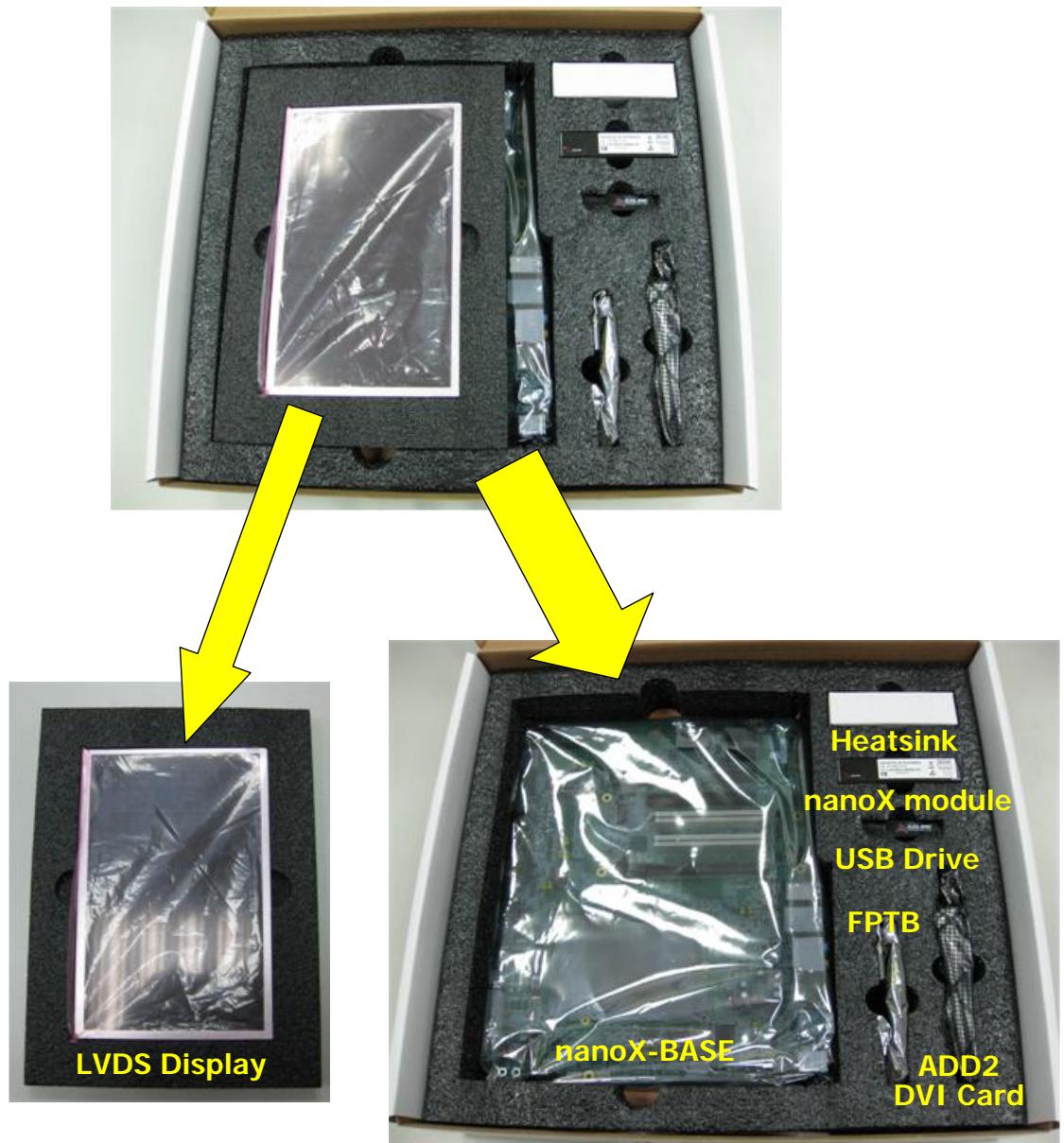
![The image is a diagram showing the breakdown of a product kit.\n\n**Top Block:**\nAn image of the full kit inside a box with foam packaging.\n\n**Connections:**\nTwo large yellow arrows originate from the top block, pointing downwards to two separate sections.\n\n**Bottom-Left Block:**\nThe left arrow points to a close-up of the large rectangular item.\n*   **Label:** LVDS Display\n\n**Bottom-Right Block:**\nThe right arrow points to the remaining contents of the box.\n*   **Labels:**\n    *   Heatsink\n    *   nanoX module\n    *   USB Drive\n    *   FPTB\n    *   nanoX-BASE\n    *   ADD2\n    *   DVI Card](.nanox-starterkit-50-1j032-1010-201/f0a669776ff6f5554ab1f5633ec6f08bd81ea70c0f6641ab8dac1555a795dca6.jpg)

Remove the EPE foam layers and check accessory boxes contain the items below:
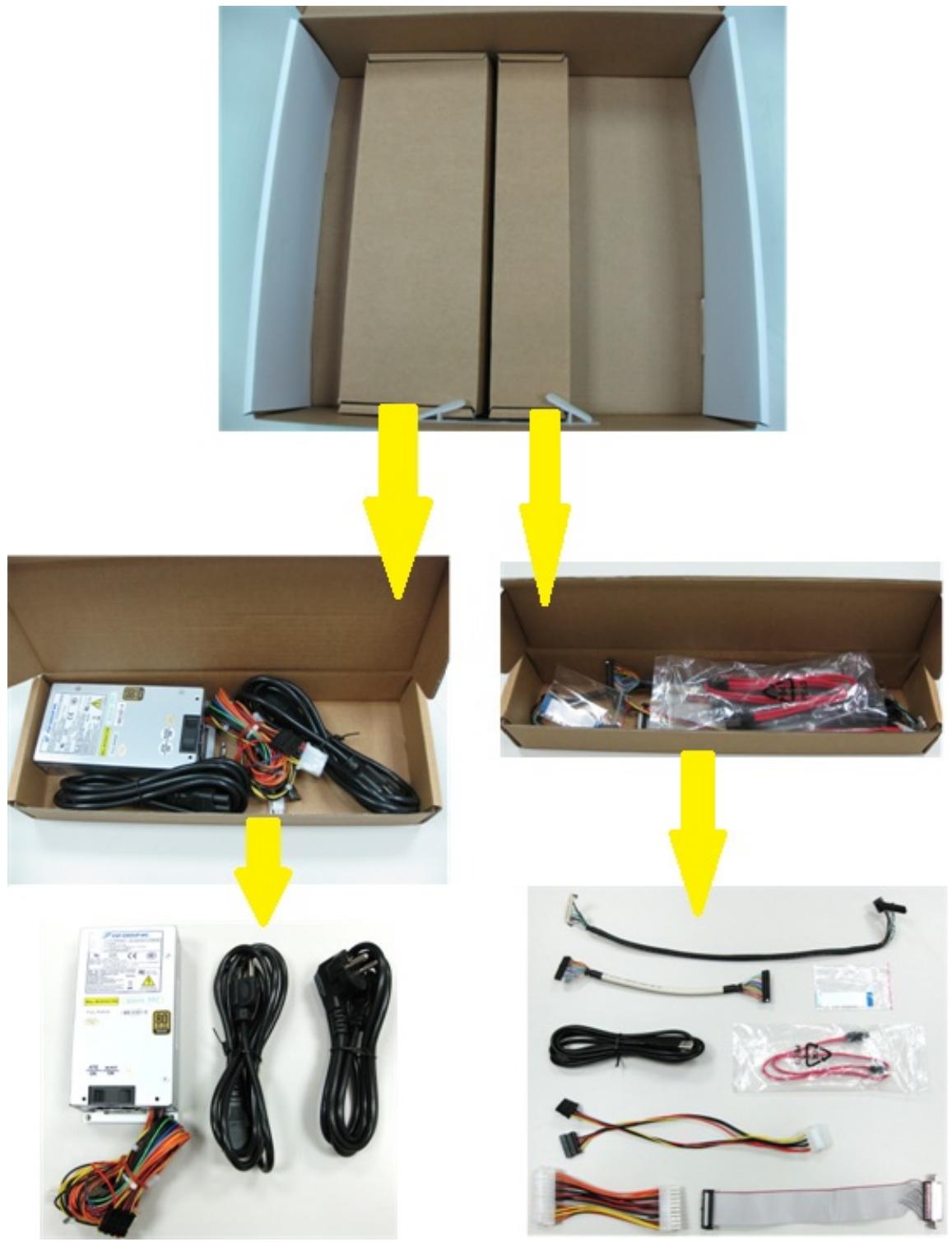
![Diagram showing assembly steps of a computer power supply box with cable and connectors, including labeled components and wiring.](.nanox-starterkit-50-1j032-1010-201/c9228d49ac94441dc548cad4532e4c2839ec7d5ecf49ea33d96cd4aed3703c58.jpg)

# 2.2 Type 1 Module Installation

If you intend to use a DVI monitor with the ADD2 DVI card, first install the SDVO flat cable onto the nanoX-ML module. Otherwise, skip ahead to Step 3.

<table><tr><td>Install SDVO flat cable onto nanoX-ML (if required)</td><td>Required items</td></tr><tr><td>Step 1Lift the locking mechanism on the nanoX-ML SDVO signal connector and insert the SDVO flat cable.&lt;img src="images/cfe5ee2d1bfaa839bf86d2a0c7ce671c7a09648b20b6846748401fb66bd1dee5.jpg"/&gt;</td><td rowspan="2">&lt;img src="images/dd6806042b4df7c478d39568cfecdfd784482a9a25b1787c692d858fd752e79b.jpg"/&gt;&lt;img src="images/5997c8ea9a779e370ba57da8c3c254ea8012487bf53a60db6e290e7a9c52fe31.jpg"/&gt;</td></tr><tr><td>Step 2Press down on the lock on the SDVO connector to secure the flat cable.&lt;img src="images/4ec231a397b45c36635723f970cc98300f10978e397ee5fee8cd48d27f3d1826.jpg"/&gt;</td></tr><tr><td>Install heatsink onto nanoX-ML module</td><td>Required items</td></tr><tr><td>Step 3Removed protective membranes from thermal pads&lt;img src="images/751461b61d1ad609e2ed8de96edd6eedfbf23aaec8db37731638e40e622f2ad5.jpg"/&gt;</td><td>&lt;img src="images/1479e14af146132c26afc5d71775e1cc246066f74286a690910d4ea394a2b7f8.jpg"/&gt;</td></tr><tr><td>Step 4Assemble heatsink onto nanoX-ML module&lt;img src="images/d321d8c3c3c48ce6249d0841b6a42989f3b8ae3869564d3ecfa52f2cd2d80a91.jpg"/&gt;&lt;img src="images/08b158324a7f585df2944f395f021d7e2c47cb466138e6c8f3e6e76c12fb300f.jpg"/&gt;</td><td>&lt;img src="images/4fa1ad5311709240bf4b9264466038dfa38af39a23e49de7ccd8f7347f871da2.jpg"/&gt;or&lt;img src="images/2e81b065455b2842cbf1201d116a01000a9e9b87b8fe2cc967dd72c38ff55de9.jpg"/&gt;</td></tr><tr><td>Install heatsink onto nanoX-ML module (cont'd)</td><td>Required items</td></tr><tr><td>Step 5Use one M2.5, L:6mm screw provided to fasten the heatsink to the nanoX-ML module&lt;img src="images/5a379f68f1c5f19d4bc65591cf1887f2c4cb40f4858f56bbdb74706334de8959.jpg"/&gt;</td><td>&lt;img src="images/80644f0473bb248bc9c752fb25a6973a9ddd524bd22faedfc30883b406cd7553.jpg"/&gt;</td></tr><tr><td>Install nanoX-ML module onto carrier board</td><td>Required items</td></tr><tr><td>Step 6Place the nanoX-ML module with heatsink onto the AB connector on the carrier board as shown&lt;img src="images/4d233f02b48e10519fdddbec8e468ee35f45231d5c72a60590d675b90e226995.jpg"/&gt;(continued below)</td><td>&lt;img src="images/9b966a2a1b4b20688ba2e3a9ad0fde57091eb6cabbf9a9aa2ba1b2ff453f104f.jpg"/&gt;&lt;img src="images/69b4bc5e5b6f35f47982dfcf4dc5d3d840aad658cc79e038969625b6429f7ef4.jpg"/&gt;</td></tr><tr><td>Install nanoX-ML module onto carrier board (cont'd)</td><td>Required items</td></tr><tr><td>Press down on the connector side of the module until it is firmly seated on the carrier board&lt;img src="images/65a60def894d8bee50103bccbd8f5fd399a55fd29420700b23d3346df8112ce7.jpg"/&gt;</td><td></td></tr><tr><td>Step 7Use two M2.5, L:16mm screws provided to secure the nanoX-ML to the carrier board (2 extra screws are provided for use with a custom carrier board with 4 mounting standoffs)&lt;img src="images/3060da6f8decf7ca4a2458ccc87aaf383de563dec6611efde991267874eed51a.jpg"/&gt;</td><td>&lt;img src="images/03c565987203995f723c09934aa95889ce8a04a9ae65e9640c6c3f1d3e608836.jpg"/&gt;</td></tr></table>

If you are not using a DVI monitor with the ADD2 DVI card, skip ahead to Section 2.4, DVI Display Interface Installation.

<table><tr><td>Install SDVO flat cable onto carrier board (if necessary)</td><td>Required items</td></tr><tr><td>Step 8Lift the locking mechanism on the nanoX-BASE SDVO input connector (CN30) and insert the SDVO flat cable.</td><td></td></tr><tr><td>&lt;img src="images/d79278137cbd9feb02b0c6be74a9915ff0726987452949f0cce19b62cb0eb685.jpg"/&gt;Insert the SDVO flat cable into nanoX-BASE SDVO input connector and press down on the locking mechanism</td><td></td></tr><tr><td>&lt;img src="images/f62b1b6299d0c6bdccf039cf5d5a40d2e9192fa84773d09bd6f54cfcbb526fc5.jpg"/&gt;</td><td></td></tr></table>

# 2.3 Type 10 Module Installation

<table><tr><td>Install heatsink onto nanoX-TC module</td><td>Required items</td></tr><tr><td>Step 1Removed protective membranes from thermal pads&lt;img src="images/dd76f7b112d0796424daea0dd30b8801d6eaf7fc47041789a5c7f5103506309a.jpg"/&gt;&lt;img src="images/0d7dd11af22ae9a69fecb66f5864fa67ef6d61cf5e81fe7bbb23b6912f204351.jpg"/&gt;</td><td>&lt;img src="images/0369a45404d5a5f80341cd2520711dd717394a4dd4a893768d05cdbf04a520ae.jpg"/&gt;</td></tr></table>

<table><tr><td>Install heatsink onto nanoX-TC module (con&#x27;td)</td><td colspan="2">Required items</td></tr><tr><td>Step 2Assemble heatsink onto nanoX-TC module&lt;img src="images/2575cbcfabcc7d3d75b5a8143e362db3f603d45d86fb69dd1a5e8fc0190cae52.jpg"/&gt;&lt;img src="images/9bd1f9e50633a09d540ccabed92883366ce0d47ac211a01f9cef4650aa64ad32.jpg"/&gt;</td><td>&lt;img src="images/fa2bf8d6e9f2acce081404b0619b1702f69409aa5c5bf78198b1400b8e67f6a6.jpg"/&gt;</td><td>&lt;img src="images/23a77e9ad3dcf3da9faf221041269755c56e0c7f7fafb10baccc7cfb7aa2ee70.jpg"/&gt;</td></tr><tr><td>Step 3Use two M2.5, L:8mm screws provided to fasten the heatsink to the nanoX-TC module&lt;img src="images/5160476abd55b1a23b9c2710db853aee4990557b48240b404a533cd638e9d105.jpg"/&gt;</td><td colspan="2">&lt;img src="images/16048e95c2e83dce9270b4713a01fdd74c7be611e3c31c9dfebd407f435c1bd1.jpg"/&gt;</td></tr></table>

<table><tr><td>Install nanoX-TC module onto carrier board</td><td>Required items</td></tr><tr><td>Step 4Place the nanoX-TC module with heatsink onto the AB connector on the carrier board as shown&lt;img src="images/bf64d545668acea2fd55b6bbc82431b2d5f4041194ed66a6ded18386b36dc9fd.jpg"/&gt;Press down on the connector side of the module until it is firmly seated on the carrier board&lt;img src="images/8dc94eae6d7434eb4a3b983d44b6635a496b120ccb267a8eed8fbcab648526fa.jpg"/&gt;</td><td>&lt;img src="images/9b4a3c1c20a772a665b1abe2f207af122f8797aa12ec58d0294e00e39749cf91.jpg"/&gt;&lt;img src="images/35e35115b23318b05d9c28bd22c807832f09e026f9045496d6093a569c4e4b70.jpg"/&gt;</td></tr><tr><td>Install nanoX-TC module onto carrier board (cont'd)</td><td>Required items</td></tr><tr><td>Step 5Use two M2.5, L:18mm screws provided to secure the nanoX-TC to the carrier board (2 extra screws are provided for use with a custom carrier board with 4 mounting standoffs)</td><td>&lt;img src="images/1a8b6727f9ef1deae486712a27f3f2e20116f660beb5430f7586d48ffd1d0d8f.jpg"/&gt;</td></tr></table>

If you not using a DVI monitor with the ADD2 DVI card, skip ahead to Section 2.5, LVDS Output using HannStar Flat Panel Display.

<table><tr><td>Install SDVO flat cable onto carrier board (if required)</td><td>Required items</td></tr><tr><td>Step 6Lift the locking mechanism on the nanoX-BASE SDVO input connector (CN30) and insert the SDVO flat cable.&lt;img src="images/67b62a2f1a083d99ef2026a0ff7a14270c9e3ede604b4a08ed8856ecc10755b6.jpg"/&gt;Insert the SDVO flat cable into nanoX-BASE SDVO input connector and press down on the locking mechanism Repeat for the SDVO output connector (CNX5).&lt;img src="images/5878969b34c7f8f0f10bdf5841df5b71dfc7b21e778bb04a36865a2f4ad9e9a9.jpg"/&gt;</td><td>&lt;img src="images/15f22574254d3b38917fc6f11fc61ea4dd17f48fa6b8998d833ee05c41ad137f.jpg"/&gt;[IMAGE]</td></tr></table>

# 2.4 DVI Display Interface Installation

# DVI Display using ADD2 DVI Adapter Card

If you intend to use a DVI monitor with the ADD2 DVI Adapter Card, be sure to first install the SDVO flat cable as described above.

<table><tr><td>Install ADD2 DVI Adapter Card</td><td>Required items</td></tr><tr><td>Step 1Plug the ADD2 DVI Adapter Card into the SDVO slot&lt;img src="images/994de5dd76a26aa7a4205117664c0fc0a3683a12aef5a09ad39522563dbd4d40.jpg"/&gt;</td><td>&lt;img src="images/5c7d25f823f03436bc502fc989d8d705f1d920d14506a83e11b10d471d66614b.jpg"/&gt;</td></tr><tr><td>Step 2Plug the DVI display connector into the ADD2 DVI Adapter Card&lt;img src="images/f77502edf6eecb184c395f61e0c38a0d791da770c0cf112211e8ec975d8a2b4a.jpg"/&gt;</td><td></td></tr></table>

# 2.5 LVDS Output using HannStar Flat Panel Display

To use the HannStar 10.1” LVDS flat panel display included with the nanoX-BASE Starter Kit, follow the instructions below.

<table><tr><td>Install Flat Panel Display</td><td>Required items</td></tr><tr><td>Step 1Set the nanoX-BASE Panel Power Jumper (JP3) is set to +3.3V (short 1-2) and the Backlight Power Jumper (JP4) is set to +5V (short 2-3) as shown below&lt;img src="images/bbdfce75b17157cb2b25e3162f2aeb242700dd8f28838aa19d60ae60e1b1e147.jpg"/&gt;</td><td></td></tr><tr><td>Step 2Connect the JAE FI-Series end of the LVDS panel cable (P/N: 30-20243-2000) to the LVDS flat panel display as shown[IMAGE]</td><td>&lt;img src="images/248925ef978cbf7ed5df7f568e8b246f3b8173fa440a112a3fdc06c4703807ad.jpg"/&gt;&lt;img src="images/3da726361a2897c20d519c1f21536223bbb7339fdf322aebefbccfb8a9d5bb78.jpg"/&gt;&lt;img src="images/e758f18650db210533901cf29aa48ca744f0210ce1c1289abd90909384355fcc.jpg"/&gt;</td></tr><tr><td>Install Flat Panel Display (cont'd)</td><td>Required items</td></tr><tr><td>Step 3Connect the 34-pin female box header of the LVDS panel cable to CN6 of the nanoX-BASE (LVDS Output Connector)&lt;img src="images/b1d6b05c3f0b6932c5fc05ae0171db6e57f2ec0fe99d52a832e976ab6f36cf33.jpg"/&gt;</td><td>&lt;img src="images/1e62973130cd112a2824c69d285d71caf90e0ca48da96abb242b4f241e0e17a2.jpg"/&gt;</td></tr><tr><td>Step 9Connect the 8-pin female box header of the LVDS panel cable to CN7 of the nanoX-BASE (Backlight Control Connector)&lt;img src="images/16a8ee4505012452070d8a4967d1091d60dd2bd101978be79425fa2e92dc1345.jpg"/&gt;</td><td></td></tr></table>

# Using the Flat Panel Transfer Board

Included with the nanoX Starter Kit is the Flat Panel Transfer Board (FPTB) which is intended for prototyping and verification of LVDS and TTL flat panel displays with COM Express systems. The FPTB is equipped with an LVDS-to-TTL converter to allow users to implement TTL displays with COM Express systems that support LVDS only. Onboard PWM circuitry supports backlight control for LVDS and TTL displays.

For detailed instructions on how to connect a TTL flat panel display to the nanoX-BASE using the FPTB, see Chapter 3 on page 33.

# 2.6 Power and I/O Connections

<table><tr><td>Connect the Power Supply</td><td>Required items</td></tr><tr><td>Plug the ATX connector of the power supply into CN1 of the nanoX-BASE&lt;img src="images/f5a2d019f4211c4e93b9593195daa1f0dec49960aacb3feda7f65c1491b267ce.jpg"/&gt;Plug the ATX 12V 4-pin connector of the power supply into the nanoX-BASE&lt;img src="images/0a45686b6d7d16922b3bd29166b31f2046d9fdac544dff27c717cc3d63ea97c4.jpg"/&gt;</td><td>&lt;img src="images/da653d023060d9b62ca66d2b8261100bc3f607ce61e3dfd5b998b388c3248472.jpg"/&gt;</td></tr></table>

![Close-up of a green circuit board with multiple colored wires and connectors, no visible text or symbols](.nanox-starterkit-50-1j032-1010-201/0fe27d8cd8dcb1b533599e9aee2b9c241964aa7ee5f8ac98f6cbd98915579eef.jpg)

![The image displays a standard safety warning sign featuring a yellow triangle with a black border. Inside the triangle is a black exclamation point. Below the triangle, the word 'CAUTION:' is written in black capital letters.](.nanox-starterkit-50-1j032-1010-201/657550f3ba5d54fb33492fbce0638f9a24bbe6fec8d67a6f6f535355750057de.jpg)

DO NOT plug the ATX 12V 4-pin connector of the power supply into the ATX 24-pin power connector on the nanoX-BASE

<table><tr><td>Connect the Power Supply (cont&#x27;d)</td><td>Required items</td></tr><tr><td>Plug power cord into the power supply&lt;img src="images/6d2ce2feafdfbc47f8323228ac7bbfd16d55181dbe606b6207843ce8553db5e5.jpg"/&gt;</td><td>&lt;img src="images/3148f85a987ee0223ffa86b3a56d4c07ab5d88885ea16335085d9f1f0ff433f4.jpg"/&gt;</td></tr><tr><td>Connect the Keyboard and Mouse</td><td></td></tr><tr><td>Plug keyboard and mouse connector into nanoX-BASE&lt;img src="images/e8d1c2762997e6c914a83ed3517d2bfae5485c6f4eee961bb724b8afc8943e48.jpg"/&gt;</td><td></td></tr></table>

# 2.7 Powering Up the nanoX-BASE System

To power up the nanoX-BASE system, follow the steps below.

<table><tr><td>Powering Up the nanoX-BASE System</td><td>Required items</td></tr><tr><td>Press the Power Button SW1.</td><td></td></tr><tr><td>&lt;img src="images/99ad6a1efef2086ef321a025e5e6a90ebfcc39249590dcad595fdc909a441b0a.jpg"/&gt;</td><td></td></tr><tr><td>The POST LEDs on the nanoX-BASE will display the bootup status – &quot;d5&quot; indicates a successful boot</td><td></td></tr><tr><td>&lt;img src="images/3bdb6481b355bd72a896d0662cddbd5061eaa171ed0b97095889c49fd89835c6.jpg"/&gt;</td><td></td></tr><tr><td>The monitor will display the BIOS boot screen</td><td></td></tr><tr><td>&lt;img src="images/8f7c5b44ba007c8a57e93b7e3cd38ce206603d07b27d2ab2d9d6be58d3fde884.jpg"/&gt;</td><td></td></tr></table>

# 3 Using a TTL Flat Panel Display

Included with the nanoX Starter Kit is the Flat Panel Transfer Board (FPTB) which is intended for prototyping and verification of LVDS and TTL flat panel displays with COM Express systems. The FPTB is equipped with an LVDS-to-TTL converter to allow users to implement TTL displays with COM Express systems that support LVDS only. Onboard PWM circuitry supports backlight control for LVDS and TTL displays. For a complete description of the FPTB and its applications, refer to the Flat Panel Transfer Board User's Manual.

Instructions on how to connect a TTL flat panel display to the nanoX-BASE using the FPTB are provided below.

# 3.1 Overview

The FPTB provides LVDS-to-TTL conversion and backlight control for use with an ADLINK reference carrier board and TTL display. The user must provide the cable connection from the FPTB's TTL output and backlight control connectors to the TTL panel inputs.

![Based on the provided image, here is the description of the flowchart/block diagram:\n\n**Labeled Blocks:**\n*   **nanoX/Express-BASE Carrier Board**: A large green rectangle on the left containing a smaller box labeled 'LVDS output'.\n*   **FPTB**: A green circuit board image in the center.\n*   **TTL Display**: A large grey rectangle on the right.\n\n**Connections and Labels:**\n*   **LVDS-to-LVDS cable**: A blue double-headed arrow connects the 'LVDS output' box to the FPTB board. The text above it reads 'LVDS-to-LVDS cable' and 'ADLINK P/N: 30-20449-0000'.\n*   **5V and 12V Input**: A blue arrow points upward into the bottom right corner of the FPTB board.\n*   **Backlight control**: A red dashed line forms a loop above the FPTB board, with arrowheads pointing towards the board's top connectors.\n*   **TTL Signal**: A red arrow points from the TTL Display towards the FPTB board.](.nanox-starterkit-50-1j032-1010-201/0b57f303f4959b2dfdcb7bacf6cef9f893b9c32146d0837a1b990cef7b2a9cb3.jpg)

nanoX/Express-BASE → FPTB → TTL Display:

# 3.2 Connectors and Jumpers

# Board Layout

![CN1\nCN5\nJP1\nCN6\nJP2\nCN8\nJP5\nCN4\nJP4](.nanox-starterkit-50-1j032-1010-201/f1105285de1401b2df46c96472995603923a34ae6078a164a70edd873286b738.jpg)

FPTB (Flat Panel Transfer Board) Connector and Jumper Locations

<table><tr><td>Connector</td><td>Description</td></tr><tr><td>CN1</td><td>Power Connector</td></tr><tr><td>CN4</td><td>LVDS Input Connector</td></tr><tr><td>CN5</td><td>TTL Output Connector</td></tr><tr><td>CN6</td><td>LVDS Output Connector</td></tr><tr><td>CN8</td><td>Backlight Control Connector</td></tr><tr><td>JP1</td><td>Backlight Voltage Jumper</td></tr><tr><td>JP2</td><td>Panel Voltage Jumper</td></tr><tr><td>JP4</td><td>LVDS/TTL Mode Selector Jumper</td></tr><tr><td>JP5</td><td>Backlight Control Mode Jumper</td></tr></table>

# Connector Pin Definitions

CN1: Power Connector (Floppy power connector)
![Pin\nSignal\n1\n+5V\n2\nGND\n3\nGND\n4\n+12V](.nanox-starterkit-50-1j032-1010-201/6591b1bc1bd7d7c6d6f7c0c218b12198819232d3faca2fdafaf7c492459d9489.jpg)

CN4: LVDS Input Connector (2x17 box header, 2.00 mm pitch)

<table><tr><td rowspan="18"></td><td>Pin</td><td>Signal</td><td>Pin</td><td>Signal</td></tr><tr><td>1</td><td>LVDS_CLK_A</td><td>2</td><td>LVDS_DTA_A</td></tr><tr><td>3</td><td>PNL_PWR</td><td>4</td><td>PNL_PWR</td></tr><tr><td>5</td><td>GND</td><td>6</td><td>LVDS_A-N0</td></tr><tr><td>7</td><td>LVDS_A-P0</td><td>8</td><td>VDD_EN</td></tr><tr><td>9</td><td>LVDS_A-N1</td><td>10</td><td>LVDS_A-P1</td></tr><tr><td>11</td><td>BL_EN_2</td><td>12</td><td>LVDS_A-P2</td></tr><tr><td>13</td><td>LVDS_A-N2</td><td>14</td><td>N.C</td></tr><tr><td>15</td><td>LVDS_ACLK_N</td><td>16</td><td>LVDS_ACLK_P</td></tr><tr><td>17</td><td>PNL_PWR</td><td>18</td><td>LVDS_A-P3</td></tr><tr><td>19</td><td>LVDS_A-N3</td><td>20</td><td>GND</td></tr><tr><td>21</td><td>LVDS_B-N0</td><td>22</td><td>LVDS_B-P0</td></tr><tr><td>23</td><td>GND</td><td>24</td><td>LVDS_B-N1</td></tr><tr><td>25</td><td>LVDS_B-P1</td><td>26</td><td>GND</td></tr><tr><td>27</td><td>LVDS_B-N2</td><td>28</td><td>LVDS_B-P2</td></tr><tr><td>29</td><td>GND</td><td>30</td><td>LVDS_BCLK_P</td></tr><tr><td>31</td><td>LVDS_BCLK_N</td><td>32</td><td>N.C</td></tr><tr><td>33</td><td>LVDS_B-P3</td><td>34</td><td>LVDS_B-N3</td></tr></table>

CN5: TTL Output Connector (2x20 box header, 2.00 mm pitch)

<table><tr><td>Pin</td><td>Signal</td><td>Pin</td><td>Signal</td></tr><tr><td>1</td><td>GND</td><td>2</td><td>FCLK</td></tr><tr><td>3</td><td>GND</td><td>4</td><td>FR0</td></tr><tr><td>5</td><td>FR1</td><td>6</td><td>FR2</td></tr><tr><td>7</td><td>GND</td><td>8</td><td>FR3</td></tr><tr><td>9</td><td>FR4</td><td>10</td><td>FR5</td></tr><tr><td>11</td><td>GND</td><td>12</td><td>FR6</td></tr><tr><td>13</td><td>FR7</td><td>14</td><td>FG0</td></tr><tr><td>15</td><td>GND</td><td>16</td><td>FG1</td></tr><tr><td>17</td><td>FG2</td><td>18</td><td>FG3</td></tr><tr><td>19</td><td>GND</td><td>20</td><td>FG4</td></tr><tr><td>21</td><td>FG5</td><td>22</td><td>GND</td></tr><tr><td>23</td><td>FG6</td><td>24</td><td>FG7</td></tr><tr><td>25</td><td>FB0</td><td>26</td><td>GND</td></tr><tr><td>27</td><td>FB1</td><td>28</td><td>FB2</td></tr><tr><td>29</td><td>FB3</td><td>30</td><td>GND</td></tr><tr><td>31</td><td>FB4</td><td>32</td><td>FB5</td></tr><tr><td>33</td><td>FB6</td><td>34</td><td>GND</td></tr><tr><td>35</td><td>FB7</td><td>36</td><td>HS (HSYNC)</td></tr><tr><td>37</td><td>VS (VSYNC)</td><td>38</td><td>GND</td></tr><tr><td>39</td><td>DE (DATA ENBLE)</td><td>40</td><td>GND</td></tr></table>

CN6: LVDS Output Connector (2x17 box header, 2.00 mm pitch)
![| Pin | Signal |\n|---|---|\n| 1 | LVDS_CLK_A |\n| 2 | 2 |\n| 3 | PNL_PWR |\n| 4 | 4 |\n| 5 | GND |\n| 6 | 6 |\n| 7 | LVDS_A-P0 |\n| 8 | 8 |\n| 9 | LVDS_A-N1 |\n| 10 | 10 |\n| 11 | BL_EN_2 |\n| 12 | 12 |\n| 13 | LVDS_A-N2 |\n| 14 | 14 |\n| 15 | LVDS_ACLK_N |\n| 16 | 16 |\n| 17 | PNL_PWR |\n| 18 | 18 |\n| 19 | LVDS_A-N3 |\n| 20 | 20 |\n| 21 | LVDS_B-N0 |\n| 22 | 22 |\n| 23 | GND |\n| 24 | 24 |\n| 25 | LVDS_B-P1 |\n| 26 | 26 |\n| 27 | LVDS_B-N2 |\n| 28 | 28 |\n| 29 | GND |\n| 30 | LVDS_BCLK_P |\n| 31 | LVDS_BCLK_N |\n| 32 | 32 |\n| 33 | LVDS_B-P3 |\n| 34 | 34 |\nLVDS_DTA_A\nPNL_PWR\nGND\nLVDS_A-N0\nVDD_EN\nLVDS_A-P1\nLVDS_A-P2\nN.C\nLVDS_ACLK_P\nLVDS_A-P3\nGND\nLVDS_B-P0\nLVDS_B-N1\nGND\nLVDS_B-P2\nLVDS_BCLK_P\nN.C\nLVDS_B-N3](.nanox-starterkit-50-1j032-1010-201/32611e0749b12688e17c8e6e274076da4c7b7ba91982952ca105357ec6e72ae0.jpg)

CN8: Backlight Control Connector (2x4 box header, 2.54 mm pitch)
![1\n2\n3\n4\n5\n6\n7\n8](.nanox-starterkit-50-1j032-1010-201/b7855a1cfbc7f271cf735ec7e2d5fc6d8f5613f5b9e57db24fe973347b2dcd6a.jpg)

<table><tr><td>Pin</td><td>Signal</td><td>Pin</td><td>Signal</td></tr><tr><td>1</td><td>GND</td><td>2</td><td>PNL_PWR</td></tr><tr><td>3</td><td>BL_CTRL</td><td>4</td><td>GND</td></tr><tr><td>5</td><td>LVDS_BL_EN</td><td>6</td><td>GND</td></tr><tr><td>7</td><td>N.C.</td><td>8</td><td>BLK_PWR</td></tr></table>

# Jumper Settings

# JP1: Backlight Voltage

![The image displays a vertical stack of three rounded rectangular sections. The top section is yellow and contains two small white squares side-by-side. The middle section is light grey and contains two small grey squares side-by-side. The bottom section is light grey and contains two small grey squares on the left and one black square on the right.](.nanox-starterkit-50-1j032-1010-201/220474537c8d506f7be569eb9ebc5aa8c32045d261f12a899de826fcd50978f6.jpg)

<table><tr><td>Jumper</td><td>Status</td></tr><tr><td>1 - 2</td><td>+12V</td></tr><tr><td>3 – 4</td><td>Reserved</td></tr><tr><td>5 – 6</td><td>+5V*</td></tr></table>

# JP2: Panel Voltage

![The image displays a vertical column of five rectangular shapes. The top shape is a yellow rectangle containing two small white squares. Below it are four grey rounded rectangles stacked vertically. The top three grey rectangles each contain two small white squares. The bottom-most grey rectangle contains a small white square on the left and a black square on the right.](.nanox-starterkit-50-1j032-1010-201/b2e6a877bf6977438968bf78796516377c6a1454090581e6183f5fa4d52cbac8.jpg)

<table><tr><td>Jumper</td><td>Status</td></tr><tr><td>1 - 2</td><td>+12V</td></tr><tr><td>3 – 4</td><td>Reserved</td></tr><tr><td>5 – 6</td><td>+5V</td></tr><tr><td>7 - 8</td><td>Reserved</td></tr><tr><td>9 - 10</td><td>+3.3V*</td></tr></table>

# JP4: LVDS/TTL Mode

![The image displays a remote control with a vertical column of four buttons. The top button is a yellow rectangle containing two small white squares. The second and third buttons are grey rounded rectangles, each containing two small white squares. The bottom button is a grey rounded rectangle containing a small white square on the left and a black square on the right.](.nanox-starterkit-50-1j032-1010-201/a696810f4e7f9425f2649a2fe700d31cc4505c0ffc209312d024239f18537cef.jpg)

<table><tr><td>Jumper</td><td>Status</td></tr><tr><td>1 - 2</td><td>TTL Output Active</td></tr><tr><td>3 - 4</td><td>Reserved</td></tr><tr><td>5 - 6</td><td>LVDS Output Active*</td></tr></table>

# JP5: Backlight Control Mode

![The image shows a vertical, rounded rectangular shape divided into two sections. The top section is grey and contains a small white square with a black border. The bottom section is yellow and features two squares: a small black square located higher up, and a larger black square frame with a white center located lower down.](.nanox-starterkit-50-1j032-1010-201/8a974fa239236bf5cd915c7495420488fbbe7d79ae3a10538e5497fa8ea52a41.jpg)

<table><tr><td>Jumper</td><td>Status</td></tr><tr><td>1 - 2</td><td>BLCTRL_PWM *</td></tr><tr><td>2 - 3</td><td>BLCTRL_VTL</td></tr></table>

Note: \* indicates default setting

# 3.3 Installation

# Jumper Settings

Make sure the Backlight Voltage jumper (JP1) and Panel Voltage jumper (JP2) are correct for the display panel you are using.

![JP1\nBC1\nR4\nR24\nR25\nR26\nJP1\n16M\nJP2\nBC23\n100V\n100V\n100V\n100V\n100V\n100V\n100V\n100V\n100V\n100V\n100V\n100V\n100V\n100V\n100V\n100V\n100V\n100V\n100V\n100V\n100\nJP2\nBC23\n100V\n100V\n100V\n100V\n100V\n100V\n100V\n100V\n100V\n100V\n100V\n100V\n100V\n100V\n100V\n100V\n100V\n100V\n16M](.nanox-starterkit-50-1j032-1010-201/ce4caee763f02143cb331a60343bb8f27429a457a89c99c0dade5e35f6227461.jpg)

Set the LVDS/TTL Mode jumper (JP4) to TTL Output Active (short pins 1-2).Set the Backlight Control Mode jumper (JP5) to PWM or Voltage Level as appropriate for your display.

# Connecting LVDS Input to FPTB

Use the FPTB LVDS-to-LVDS cable (P/N 30-20449-0000) to connect the LVDS output connector on the nanoX-BASE (CN6) to the LVDS input connector on the FPTB (CN4).

<table><tr><td>Connecting LVDS Input to FPTB</td><td>Required items</td></tr><tr><td>Plug the LVDS-to-LVDS cable into nanoX-BASE CN6&lt;img src="images/e211c687fb65443cb637b8bd3f66a1a2f7c45abb7995008dd306ae22113421a9.jpg"/&gt;</td><td rowspan="2">&lt;img src="images/70a10cdc37a71f94c3c745af437ab475de99e55a2e87e367f54406e83e8e7ba9.jpg"/&gt;LVDS-to-LVDS cable</td></tr><tr><td>Plug the LVDS-to-LVDS cable connector into FPTB CN4&lt;img src="images/c2b05cbbf3238fd91530a110c620a26f047d4a5e21af2192542cc7bdb157d61b.jpg"/&gt;</td></tr></table>

# TTL Output to Display Panel

Make the appropriate cable to connect the TTL Output Connector (CN5) and Backlight Control Connector (CN8) on the FPTB to the target TTL display panel.

# FPTB Power Connector

Connect the Floppy Drive power connector of your power supply to the FPTB Power Connector (CN1).

![Close-up of a gloved hand holding a white plastic connector with red and yellow wires, next to a green printed circuit board (no visible text or symbols)](.nanox-starterkit-50-1j032-1010-201/23fda1b78a0a43bd59b53dcb2ac520749ded4a3e26a8a45050da12ba7f738936.jpg)

# Power Up the System

Assemble the rest of your system as required and power it on. An example nanoX-BASE system with FPTB connected to a TTL display panel is shown below.

![Two electronic circuit boards with CPU and power supply components, no visible text or symbols on the boards themselves.](.nanox-starterkit-50-1j032-1010-201/680b882e0198d1561cd3bc444579bf7d7af7dcf7e9fcf5be03eca111da546453.jpg)

# Technical Support

Contact us should you require any service or assistance.

# ADLINK Technology, Inc.

Address: 9F, No.166 Jian Yi Road, Zhonghe District

New Taipei City 235, Taiwan

新北市中和區建一路 166號 9樓

+886-2-8226-5877

Fax: +886-2-8226-5717

Email: service@adlinktech.com

# Ampro ADLINK Technology, Inc.

Address: 5215 Hellyer Avenue, #110, San Jose, CA 95138, USA

+1-408-360-0200

Toll Free: +1-800-966-5200 (USA only)

+1-408-360-0222

Email: info@adlinktech.com

# ADLINK Technology (China) Co., Ltd.

Address: 上海市浦东新区张江高科技园区芳春路 300 号 (201203)

300 Fang Chun Rd., Zhangjiang Hi-Tech Park,

Pudong New Area, Shanghai, 201203 China

Tel: +86-21-5132-8988

+86-21-5132-3588

Email: market@adlinktech.com

# ADLINK Technology Beijing

Address: 北京市海淀区上地东路 1 号盈创动力大厦 E 座 801 室(100085)

Rm. 801, Power Creative E, No. 1, B/D

Shang Di East Rd., Beijing, 100085 China

+86-10-5885-8666

+86-10-5885-8625

Email: market@adlinktech.com

# ADLINK Technology Shenzhen

Address: 深圳市南山区科技园南区高新南七道 数字技术园

A1 栋 2 楼 C 区 (518057)

2F, C Block, Bldg. A1, Cyber-Tech Zone, Gao Xin Ave. Sec. 7,

High-Tech Industrial Park S., Shenzhen, 518054 China

+86-755-2643-4858

Fax: +86-755-2664-6353

Email: market@adlinktech.com

# LiPPERT ADLINK Technology GmbH

Address: Hans-Thoma-Strasse 11, D-68163, Mannheim, Germany

+49-621-43214-0

+49-621 43214-30

Email: emea@adlinktech.com

# ADLINK Technology, Inc. (French Liaison Office)

Address: 15 rue Emile Baudot, 91300 Massy CEDEX, France

Tel: +33 (0) 1 60 12 35 66

Fax: +33 (0) 1 60 12 35 66

# ADLINK Technology Japan Corporation

Address: 〒101-0045 東京都千代田区神田鍛冶町 3-7-4

神田 374 ビル 4F

KANDA374 Bldg. 4F, 3-7-4 Kanda Kajicho,

Chiyoda-ku, Tokyo 101-0045, Japan

Tel: +81-3-4455-3722

Fax: +81-3-5209-6013

Email: japan@adlinktech.com

# ADLINK Technology, Inc. (Korean Liaison Office)

Address: 서울시 서초구 서초동 1506-25 한도 B/D 2 층

2F, Hando B/D, 1506-25, Seocho-Dong, Seocho-Gu,

Seoul 137-070, Korea

+82-2-2057-0565

+82-2-2057-0563

Email: korea@adlinktech.com

# ADLINK Technology Singapore Pte. Ltd.

Address: 84 Genting Lane #07-02A, Cityneon Design Centre,

Singapore 349584

+65-6844-2261

Fax: +65-6844-2263

Email: singapore@adlinktech.com

# ADLINK Technology Singapore Pte. Ltd. (Indian Liaison Office)

Address: 1st Floor, #50-56 (Between 16th/17th Cross) Margosa Plaza,

Margosa Main Road, Malleswaram, Bangalore-560055, India

Tel: +91-80-65605817, +91-80-42246107

Fax: +91-80-23464606

Email: india@adlinktech.com

# ADLINK Technology, Inc. (Israeli Liaison Office)

Address: 6 Hasadna St., Kfar Saba 44424, Israel

Tel: +972-9-7446541

+972-9-7446542

Email: israel@adlinktech.com
[🔗 Link to the original document](.nanox-starterkit-50-1j032-1010-201/nanox-starterkit-50-1j032-1010-201.pdf)
