# NEON-2000-JNO Series

AI Smart Camera

User's Manual

![Exterior view of a modern digital camera with visible lens and control panel (no text or symbols on body)](.neon-2000-jno-50m-00107-1000-10/788e58b75a5fbf62b9ecf318ca784d4aa095904202433d8d597c32ff7fe664fb.jpg)

Manual Rev.: 1.0

Revision Date: January 31, 2023

Part No: 50M-00107-1000

Revision History

<table><tr><td>Revision</td><td>Release Date</td><td>Description of Change(s)</td></tr><tr><td>1.0</td><td>2023-01-31</td><td>Initial release</td></tr></table>

# Preface

# Copyright © 2023 ADLINK Technology, Inc.

This document contains proprietary information protected by copyright. All rights are reserved. No part of this manual may be reproduced by any mechanical, electronic, or other means in any form without prior written permission of the manufacturer.

# Disclaimer

The information in this document is subject to change without prior notice in order to improve reliability, design, and function and does not represent a commitment on the part of the manufacturer.

In no event will the manufacturer be liable for direct, indirect, special, incidental, or consequential damages arising out of the use or inability to use the product or documentation, even if advised of the possibility of such damages.

# Environmental Responsibility

ADLINK is committed to fulfill its social responsibility to global environmental preservation through compliance with the European Union's Restriction of Hazardous Substances (RoHS) directive and Waste Electrical and Electronic Equipment (WEEE) directive. Environmental protection is a top priority for ADLINK. We have enforced measures to ensure that our products, manufacturing processes, components, and raw materials have as little impact on the environment as possible. When products are at their end of life, our customers are encouraged to dispose of them in accordance with the product disposal and/or recovery programs prescribed by their nation or company.

# Trademarks

Product names mentioned herein are used for identification purposes only and may be trademarks and/or registered trademarks of their respective companies.

# Conventions

Take note of the following conventions used throughout this manual to make sure that users perform certain tasks and instructions properly.

![The image displays a white document icon with a folded top-right corner (a 'dog-ear'). It features horizontal gray lines resembling text and is overlaid with a large, bold red checkmark.](.neon-2000-jno-50m-00107-1000-10/878eba4080d71ce958bfd00957f84ea83084cd8a23d45ab156cdb698ca077b0d.jpg)
NOTE:

Additional information, aids, and tips that help users perform tasks.

![The image features a yellow equilateral triangle with a thick black outline, serving as a standard warning sign. Centered inside the triangle is a large black exclamation point.](.neon-2000-jno-50m-00107-1000-10/19e523be90b08d286ebcf851ca4d2ee01fe3c0cceeadf5124c5766bc0b400503.jpg)
CAUTION:

Information to prevent minor physical injury, component damage, data loss, and/or program corruption when trying to complete a task.

ATTENTION: Informations destinées à prévenir les blessures corporelles mineures, les dommages aux composants, la perte de données et/ou la corruption de programme lors de l'exécution d'une tâche.

![A red triangular warning sign featuring a large white exclamation point in its center.](.neon-2000-jno-50m-00107-1000-10/d5a9eb5c5d2ff746f2046c61c9a8552b29e2f7e9638010b836eaa8bbd234c8e4.jpg)
WARNING:

Information to prevent serious physical injury, component damage, data loss, and/or program corruption when trying to complete a specific task.

AVERTISSEMENT: Informations destinées à prévenir les blessures corporelles graves, les dommages aux composants, la perte de données et/ou la corruption de programme lors de l'exécution d'une tâche spécifique.

# Table of Contents

# Revision History...... ii

# Preface...... iii

# List of Figures ...... vii

# List of Tables ix

# 1 Introduction ...... 1

1.1 Overview.... 1
1.2 Features.... 2
1.3 General Specifications.... 3
1.4 Mechanical Dimensions.... 6
1.5 Accessories 8

# 2 Connectors and I/O 9

2.1 Bottom Side I/O and Connector Description.... 10
2.2 Top Side I/O and Connector Description 13
2.3 Front Side I/O and Connector Description.... 15

# 3 Getting Started 17

3.1 Mounting 17
3.2 Digital I/O Connection Example.... 18
3.3 Attaching a Lens 19
3.4 Power and Peripheral Connections 20
3.5 Log In.... 22
3.6 Image Capture and Inference 23
3.7 Neon-20XA Trigger Control 24

# Important Safety Instructions 27

# Consignes de Sécurité Importante.... 29

# Getting Service.... 31

This page intentionally left blank.

# List of Figures

Figure 2-1: NEON-2000-JNO Orientation 9

Figure 2-2: Bottom Side I/O and Connectors....10

Figure 2-3: D-sub I/O Connector....11

Figure 2-4: DC Jack Connector....12

Figure 2-5: Top Side I/O and Connectors 13

Figure 2-6: Wafer Connector....14

Figure 2-7: Front Side I/O and Connectors....15

Figure 3-1: NEON-2000-JNO Mounting Holes....17

Figure 3-2: Digital Input Schematic Diagram 18

Figure 3-3: Digital Output Schematic Diagram....18

Figure 3-4: Lens Attachment Assembly 19

Figure 3-5: Separate Power and Peripheral Connections......20

Figure 3-6: Combined Power and Peripheral Connections......21

Figure 3-7: Neon-20XA Trigger API Function Options....24

This page intentionally left blank.

# List of Tables

Table 1-1: NEON-2000-JNO Model and Sensor Specifications .. 1

Table 1-2: NEON-2000-JNO General Specifications......4

Table 2-1: Bottom Side I/O and Connectors.... 10

Table 2-2: D-sub I/O Connector Pin Definitions....11

Table 2-3: D-sub I/O Connector Specification .... 12

Table 2-4: DC Jack Pin Definitions....12

Table 2-5: Top Side I/O and Connectors 13

Table 2-6: Wafer Connector Pin Definitions .... 14

Table 2-7: Front Side I/O and Connectors....15

This page intentionally left blank.

# 1 Introduction

# 1.1 Overview

The NEON-2000-JNO series is an open camera platform equipped with an NVIDIA® Jetson™ Nano module supporting a series of image sensors providing industrial DI/O capabilities. It is designed for deep learning inference or other vision applications that requires a GPU at the edge. The system has Ubuntu Linux, Jetpack, camera driver and utilities pre-installed to save integration effort and avoid compatibility issues.

The following table describes the current NEON-2000-JNO models with their respective sensor specifications.

<table><tr><td>Camera Model</td><td>Image Sensor</td><td>Sensor Vendor</td><td>Sensor Module</td><td>Sensor Output</td><td>Image Capturing</td></tr><tr><td>NEON-201A-JNO</td><td>1/2.6&quot;, 2M, Global Shutter, 1920x1200, 60fps, Color</td><td>onsemi</td><td>AR0234</td><td>mipi</td><td>V4L2/Gstreamer</td></tr><tr><td>NEON-202A-JNO</td><td>1/1.8&quot;, 8M, Rolling Shutter, 3840x2160, 60fps, Color</td><td>Sony</td><td>IMX334</td><td>mipi</td><td>V4L2/Gstreamer</td></tr></table>

Table 1-1: NEON-2000-JNO Model and Sensor Specifications

# 1.2 Features

- Provides rich sample code and AI development, quick to start
▶ CPU: Quad-Core Arm® Cortex®-A57 MPCore processor
▶ GPU: NVIDIA Maxwell architecture with 128 NVIDIA CUDA® cores and 16GB eMMC
▶ USB3 sensor interface compatible with the most machine vision software
▶ Type-C connector supports DC power, DisplayPort and USB signal, reducing cabling
▶ Preinstalled Ubuntu and software suite on microSD card, plug and play
▶ Highly integrated and compact system that is easy to deploy

# 1.3 General Specifications

▶ Lens mount: C-mount
▶ Total weight: &lt;700g (without lens)
▶ Operating temperature (tested with YOLOv4)
▷ NEON-20XA-JNO series, 0°C to 55°C with 0.6 m/s airflow at 15W mode
▶ Power consumption: &lt;40W
▶ Computing module: NVIDIA Jetson Nano
▷ CPU: Quad-Core Arm® Cortex®-A57 MPCore processor
▷ GPU: NVIDIA Maxwell architecture with 128 NVIDIA CUDA® cores
Built-in memory and storage: 4 GB 64-bit LPDDR4, 1600MHz 25.6 GB/s, 16GB eMMC and 32G microSD card

▶ Camera I/O and connectors

▷ 1x Type-C for power input, DisplayPort and USB signals
▷ 1x DC Jack for 12-24V DC input
▷ 1x GbE Ethernet port
▷ 1x 15-pin D-sub for DI/O and COM which includes:
▷4x GPI/O, including 1x Camera Trigger In and 1x Trigger Out
▷1x COM
1x 32G microSD card with preinstalled OS and required software
▷ 1x wafer connector and 1x Micro-USB for system flashing and debugging

![The image displays a line-drawing icon of a document with horizontal lines, overlaid with a large red checkmark.](.neon-2000-jno-50m-00107-1000-10/3b74e0a2fbaeaa9742f9809f83f2c91ccfab23aa70fc826e0d1cab8fae76cbba.jpg)
NOTE:

1. When powering from the DC Jack, the Type-C connector can provide 3W of power to an external device such as a Type-C hub. Devices requiring more than 3W cannot be used.
2. DC power can be from the Type-C connector or DC jack.
3. Use only recommended ADLINK power adapters.
4. The camera boots from the preinstalled microSD card that cannot be removed. To change the microSD card, constant ADLINK.

&lt;table&gt;<tr><td>Model</td><td>NEON-201A-JNO</td><td>NEON-202A-JNO</td></tr><tr><td colspan="3">Image Sensor</td></tr><tr><td>Resolution (HxV)</td><td>1920x1200</td><td>3840x2160</td></tr><tr><td>Resolution</td><td>2M</td><td>8M</td></tr><tr><td>Frame Rate (fps)</td><td>60</td><td>30</td></tr><tr><td>Color/Mono</td><td>Color</td><td>Color</td></tr><tr><td>Shutter</td><td>Global</td><td>Rolling</td></tr><tr><td>Sensor Size</td><td>1/2.6&quot;</td><td>1/1.8&quot;</td></tr><tr><td>Pixel Size (μm)</td><td>3 x 3</td><td>2.0 x 2.0</td></tr><tr><td>Sensor Vendor</td><td>onsemi</td><td>Sony</td></tr><tr><td>Sensor Model</td><td>AR0234</td><td>IMX334</td></tr><tr><td>Image Capturing Software</td><td colspan="2">V4L2 &amp; Gstreamer</td></tr><tr><td>Image Sensor Trigger Mode</td><td>External HW trigger, SW trigger, free run</td><td>SW trigger, free run</td></tr><tr><td>Lens Mount</td><td colspan="2">C Mount</td></tr><tr><td colspan="3">System</td></tr><tr><td>Computing Platform</td><td colspan="2">NVIDIA Jetson Nano</td></tr><tr><td>CPU</td><td colspan="2">6-core NVIDIA Carmel ARM®v8.2 64-bit CPU 6 MB L2 + 4 MB L3</td></tr><tr><td>Supported OS</td><td colspan="2">Ubuntu 18.04</td></tr><tr><td>GPU</td><td colspan="2">NVIDIA Maxwell architecture with 128 NVIDIA CUDA® cores</td></tr><tr><td>Storage</td><td colspan="2">16G eMMC (built-in Nano module) and pre-installed 32G microSD card</td></tr><tr><td>Memory</td><td colspan="2">8 GB 128-bit LPDDR4/16G eMMC (built-in Nano module)</td></tr></table>

Table 1-2: NEON-2000-JNO General Specifications

<table><tr><td>Model</td><td>NEON-201A-JNO</td><td>NEON-202A-JNO</td></tr><tr><td colspan="3">Connectors and Functions</td></tr><tr><td>Ethernet</td><td colspan="2">Supports 10/100/1000 Mb</td></tr><tr><td rowspan="4">USB Type C</td><td colspan="2">Video output (DisplayPort), 1920x1080 @ 30fps</td></tr><tr><td colspan="2">1x USB3 and 1x USB2</td></tr><tr><td colspan="2">Power supply for the camera (when connected to Type-C charger or adaptor)</td></tr><tr><td colspan="2">Power supply (5 W) for external Type-C Hub (when connected to Type-C hub)</td></tr><tr><td rowspan="2">D-sub</td><td colspan="2">4x DI and 4x DO</td></tr><tr><td colspan="2">1x UART (TXD, RXD, GND)</td></tr><tr><td>Micro USB</td><td colspan="2">USB OTG (for system flash)</td></tr><tr><td>Wafer Connector</td><td colspan="2">For system flash</td></tr><tr><td colspan="3">Mechanical &amp; Power</td></tr><tr><td>Dimensions</td><td colspan="2">123.3 x 77.5 x 66.81 mm</td></tr><tr><td>Weight</td><td colspan="2">700g</td></tr><tr><td>Power Input</td><td colspan="2">DC Jack (12-24V DC) or Type-C (15V DC)</td></tr><tr><td>Power Consumption</td><td colspan="2">&lt;40W (camera only)</td></tr><tr><td colspan="3">Environmental &amp; Certification</td></tr><tr><td>Operating Temperature</td><td colspan="2">0°C to 55°C</td></tr><tr><td>Storage Temperature</td><td colspan="2">-20°C to 70°C</td></tr><tr><td>Humidity</td><td colspan="2">40% to 75% (non-condensing)</td></tr><tr><td>Vibration</td><td colspan="2">Operating, 5 to 500 Hz, 5 Grms, 3 axes</td></tr><tr><td>Shock</td><td colspan="2">Operating, 11ms duration, 30G, half sine, 3 axes</td></tr><tr><td>ESD</td><td colspan="2">Contact +/- 4kV, Air +/- 8kV</td></tr><tr><td>EMC</td><td colspan="2">CE and FCC Class A (EN61000-4/-2)</td></tr><tr><td>Safety</td><td colspan="2">UL and cB</td></tr></table>

Table 1-2: NEON-2000-JNO General Specifications

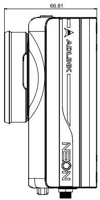
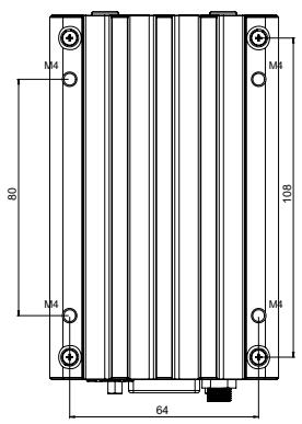
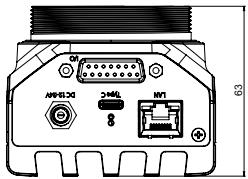
# 1.4 Mechanical Dimensions

This section provides dimensions and related mechanical information for the NEON-2000-JNO.

# 1.4.1 Camera Dimensions
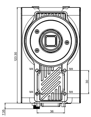
![123.30\nM4\nM4\nM4\n30\n7.35\n36](.neon-2000-jno-50m-00107-1000-10/3f4fa4c4c96270d4f81213261f7c7e9092503cbb6465df8013c9049742f3719c.jpg)

![66.81\nA-Link\nNEON](.neon-2000-jno-50m-00107-1000-10/0247c419e93f2ab48b144ed31a410561ec04b031448b76b57d01420161661a8e.jpg)

![N4\n80\nM4\nM6\n108\nM4\nM6\n64](.neon-2000-jno-50m-00107-1000-10/c6741a0f3b14f67c19411d2a6aa6c6155752fd282332638946a50dd3a8c99ed6.jpg)

![APR-51.30\n3×4x8L\nNVT\n63](.neon-2000-jno-50m-00107-1000-10/0d60354b36dd5cafe6a798dfee95c5f04bf5ade188812f114f7208ebc89133c7.jpg)

Dimensions: mm

# 1.4.2 USB Type-C Screw Lock Location and Dimensions
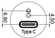
![6.80\nType C\n4.50](.neon-2000-jno-50m-00107-1000-10/40e7fe86ddd0156ddb9d4774f56ee39937f973b80d76904a3c6bdf281cece597.jpg)

Dimensions: mm

# 1.4.3 LED Light Mounting Thread
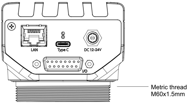
![LAN\nType C\nDC 12-24V\nI/O\nMetric thread\nM60x1.5mm](.neon-2000-jno-50m-00107-1000-10/758e1636f459bab380ab581fed9bc1c9f067b2e901661f3ee30cf68dad3b09b0.jpg)

# 1.5 Accessories

Use ADLINK recommended accessories for optimum system performance. The table below includes ADLINK verified accessories.

<table><tr><td>Accessory</td><td>Part Number</td><td>Description</td></tr><tr><td>USB Type-C cable</td><td>30-01284-0030-A0</td><td>USB Type-C (M) to USB Type-C (M), length 1.8M, with screw lock</td></tr><tr><td>USB Type-C Hub &amp; Adapter</td><td>92-99090-1010</td><td>AC 100-240V, USB – C PD2.0, DC 15V/2.3A</td></tr><tr><td>DI/O cable</td><td>30-01332-0010-A0</td><td>DB15P (M) to DB37P (M), length 3M, connected to DIN-37D-01</td></tr><tr><td>DIN-37D-01 DI/O extension board</td><td>91-14025-1020</td><td>DI/O extension board with one 37-pin D-sub connector and DIN-rail mount</td></tr><tr><td>8mm lens</td><td>92-15731-0010</td><td>Focal length 8mm, F1.4, 2/3&quot;, 3MP</td></tr><tr><td>AC/DC adaptor</td><td>31-62156-1010-A0</td><td>AC 100-240V DC, 12V/5A, DC jack</td></tr></table>

# 2 Connectors and I/O

This chapter includes the locations and descriptions of the connectors and I/O found on the NEON-2000-JNO.
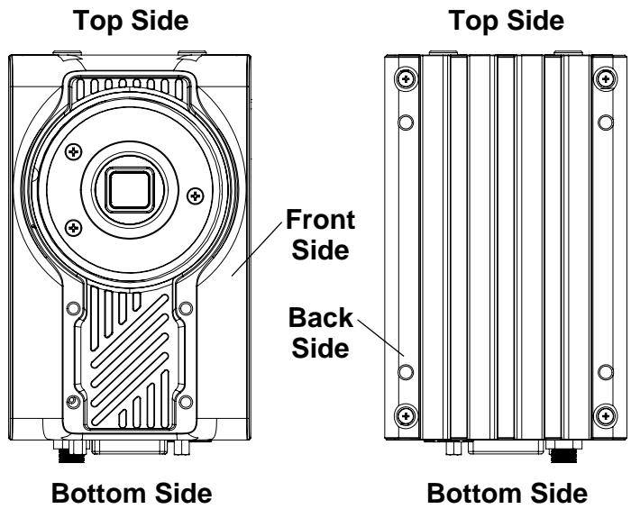
![Top Side\nFront Side\nBack Side\nBottom Side\nTop Side\nBottom Side](.neon-2000-jno-50m-00107-1000-10/51e2a31840512b24d3ddd21254af8693266ee2379c18f3c244846eb6bd4a84b2.jpg)

Figure 2-1: NEON-2000-JNO Orientation

# 2.1 Bottom Side I/O and Connector Description
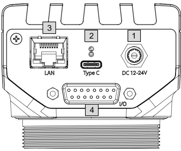
![3\nLAN\nType C\n1\nDC 12-24V\nI/O\n4](.neon-2000-jno-50m-00107-1000-10/aab916af3cfda41280042588b0bd8b1b20277ce08b95e8f7292d7d3e0ac249b7.jpg)

Figure 2-2: Bottom Side I/O and Connectors

<table><tr><td>Item</td><td>Description</td></tr><tr><td>1</td><td>DC Jack for DC input with included ADLINK AC/DC adaptor (P/N 31-62156-1010-A0)Power input: 12-24V DC at &gt;30 W</td></tr><tr><td>2</td><td>USB Type-C connector w/ screw lockSupports DisplayPort (up to 1080P @ 30 fps)The NEON-2000-JNO can be powered via this port or the DC jack</td></tr><tr><td>3</td><td>1 GbE LAN at 10/100/1000 Mbit/s</td></tr><tr><td>4</td><td>15-pin D-sub I/O connector for the digital I/O and UART. Use to connect external I/O devices such as sensors, COM and LED/strobe controllers.</td></tr></table>

Table 2-1: Bottom Side I/O and Connectors

# 2.1.1 D-sub I/O Connector

![8\n1\n15\n9](.neon-2000-jno-50m-00107-1000-10/dcfb575852b5f2c21404e737373c478c5bc62d4cabb84a1d697d14046ec4905a.jpg)

Figure 2-3: D-sub I/O Connector

<table><tr><td>Pin</td><td>Function</td><td>Pin</td><td>Function</td></tr><tr><td>1</td><td>UART - TX</td><td>2</td><td>DI/O GND</td></tr><tr><td>3</td><td>Digital output 0/Strobe output 0 (see note 2)</td><td>4</td><td>Digital output 1</td></tr><tr><td>5</td><td>Digital output 2</td><td>6</td><td>Digital output 3</td></tr><tr><td>7</td><td>UART GND</td><td>8</td><td>Reserved</td></tr><tr><td>9</td><td>UART – RX</td><td>10</td><td>DI/O GND</td></tr><tr><td>11</td><td>Digital input 0/Trigger input 0 (see note 1)</td><td>12</td><td>Digital Input 1</td></tr><tr><td>13</td><td>Digital Input 2</td><td>14</td><td>Digital Input 3</td></tr><tr><td>15</td><td>Reserved</td><td></td><td></td></tr></table>

Table 2-2: D-sub I/O Connector Pin Definitions

![The image displays a white icon of a document or sheet of paper with the top-left corner folded down. Faint horizontal lines run across the lower half of the page, suggesting text. A large, bold red checkmark is superimposed over the center of the paper.](.neon-2000-jno-50m-00107-1000-10/3473c353a13ee8d4daef94399404329fc73a94318e3a4e6f3611955657b80a97.jpg)
NOTE:

1. Pin 11 (Digital input 0/Trigger input 0) is programmable. When configured for trigger input, it is used for hardware triggering of the image sensor. Connect an external sensor signal to pin 11 and set the camera to hardware trigger mode to enable realtime or hardware triggered image capture.
2. Pin 3 (Digital output 0/Strobe output 0) is programmable. When configured for strobe output, it can be connected to an LED light/strobe controller to adjust the timing latency/delay according to the camera connected to pin 11.

<table><tr><td>I/O Category</td><td>Maximum Throughput</td><td colspan="3">Specification</td></tr><tr><td>UART</td><td>-</td><td colspan="3">Baud rate: 9600bps @ 8N1</td></tr><tr><td rowspan="4">Digital Input</td><td rowspan="4">10 KHz</td><td>Common sharing:</td><td colspan="2">1 common for sharing ground</td></tr><tr><td>Input range:</td><td colspan="2">0-5 VDC</td></tr><tr><td>High level threshold:</td><td colspan="2">2-5 VDC</td></tr><tr><td>Low level threshold:</td><td colspan="2">0-0.8 VDC</td></tr><tr><td rowspan="2">Digital Output</td><td rowspan="2">10KHz</td><td rowspan="2">Open-collector</td><td>Input voltage range:</td><td>3.3-30 VDC</td></tr><tr><td>Maximum sink current</td><td>100 mA</td></tr></table>

Table 2-3: D-sub I/O Connector Specification

# 2.1.2 DC Jack

![DC 12-24V\n1\n2](.neon-2000-jno-50m-00107-1000-10/5ed67cda90ba22e09f10f7fb109d3d64915e6590f117ff0db9d27d4fb5ed5ecb.jpg)

Figure 2-4: DC Jack Connector

<table><tr><td>Pin</td><td>Function</td><td>Description</td></tr><tr><td>1</td><td>Power</td><td>Power input</td></tr><tr><td>2</td><td>Ground</td><td>Reference ground</td></tr></table>

Table 2-4: DC Jack Pin Definitions

# 2.2 Top Side I/O and Connector Description

![5 6 7\nPower Status User\n10\nMicro USB\nSD 9\n8](.neon-2000-jno-50m-00107-1000-10/037e6ba38c6fff2b35f697c2be1587d381213753d5724d26e0836d9bc2ce2610.jpg)

Figure 2-5: Top Side I/O and Connectors

<table><tr><td>Item</td><td>Description</td></tr><tr><td>5</td><td>Power status LED. Lights green when power is connected.</td></tr><tr><td>6</td><td>Operating system status LED. Flashes orange when the system is booting, and lights when the system has booted successfully.</td></tr><tr><td>7</td><td>User define green/red LED.</td></tr><tr><td>8</td><td>microSD card slot, with 32G microSD card pre-installed with Ubuntu and required software. The camera boots from this microSD card.</td></tr><tr><td>9</td><td>Wafer connector. This connector is used to update the NEON-2000-JNO.</td></tr><tr><td>10</td><td>Micro-USB port. This connector is used to update the NEON-2000-JNO.</td></tr></table>

Table 2-5: Top Side I/O and Connectors

# 2.2.1 Wafer Connector

![9\n1\n10\n2](.neon-2000-jno-50m-00107-1000-10/b3f907ffebebe36b363c95f1073cc994f1115fe56c82ef5cdc92636761c646b5.jpg)

Figure 2-6: Wafer Connector

<table><tr><td>Pin</td><td>Function</td><td>Pin</td><td>Function</td></tr><tr><td>1</td><td>Reserved</td><td>2</td><td>Reserved</td></tr><tr><td>3</td><td>System Reset</td><td>4</td><td>GND</td></tr><tr><td>5</td><td>RECOVERY</td><td>6</td><td>GND</td></tr><tr><td>7</td><td>Reserved</td><td>8</td><td>GND</td></tr><tr><td>9</td><td>Reserved</td><td>10</td><td>GND</td></tr></table>

Table 2-6: Wafer Connector Pin Definitions

# 2.3 Front Side I/O and Connector Description

![11\n12](.neon-2000-jno-50m-00107-1000-10/ce22ab5feecde3846631bf4dcc132a576e50ccfce7251dbc682039cc5e2949bf.jpg)

![Technical line drawing of a mechanical device with labeled component (13), showing internal structure and mounting points (no text or symbols beyond labels)](.neon-2000-jno-50m-00107-1000-10/d5cf7e304c7ee2eee11a21487b5ba4640fe656d9fa746d6ae4788b6d511c2586.jpg)

Figure 2-7: Front Side I/O and Connectors

<table><tr><td>Item</td><td>Description</td></tr><tr><td>11</td><td>C-type lens mount</td></tr><tr><td>12</td><td>Image sensor</td></tr><tr><td>13</td><td>Strobe/LED light mounting thread.See “LED Light Mounting Thread” on page 7.</td></tr></table>

Table 2-7: Front Side I/O and Connectors

This page intentionally left blank.

# 3 Getting Started

# 3.1 Mounting

The NEON-2000-JNO can be mounted using the mounting screw holes on either the front (A) or back (B) sides.

Le NEON-2000-JNO peut être monté à l'aide des trous de vis de montage sur les côtés avant (A) ou arrière (B).

![The image displays technical line drawings of a mechanical device from two perspectives.\n\n**Top View:**\n*   A vertical dimension on the left reads **123.30**.\n*   A horizontal dimension at the bottom reads **36**.\n*   A horizontal dimension on the right reads **30**.\n*   Inside the central circular component is a box labeled **Sensor** and **Dia**.\n*   Four mounting holes are marked with the letter **A**.\n*   Text below the drawing reads:\n    **A: 4x M4 screws, L=6mm**\n    **4x vis M4, L=6mm**\n\n**Bottom View:**\n*   A horizontal dimension at the top reads **64**, and another at the bottom reads **64**.\n*   A vertical dimension on the left reads **80**.\n*   A vertical dimension on the right reads **108**.\n*   Four mounting holes are marked with the letter **B**.\n*   Text below the drawing reads:\n    **B: 4x M4 screws, L=6mm**\n    **4x vis M4, L=6mm**](.neon-2000-jno-50m-00107-1000-10/ae84108f986245865a88406a435741c75444bfa894a30f370434d30ede349f09.jpg)
A: 4x M4 screws, L=6mm
4x vis M4, L=6mm
B: 4x M4 screws, L=6mm
4x vis M4, L=6mm

Figure 3-1: NEON-2000-JNO Mounting Holes

# 3.2 Digital I/O Connection Example

External devices such as trigger sensors, LED light controllers or relays can be connected to the NEON-2000-JNO to implement different applications. This section shows an example of how to connect such devices.

![Camera Side\nDI 0-3\n(non-Isolation)\nMax 5V\nDI/O GND\nVDD\ncontrol circuit](.neon-2000-jno-50m-00107-1000-10/94694bc6b7da6d5b43b8a2ae31c4e7fb10f3701d424b2ed5148090b6db121431.jpg)

Figure 3-2: Digital Input Schematic Diagram

![Camera Side\ncontrol circuit\nOCP/OVP\nDO 0-3\n(non-Isolation)\nMax. 100mA\nload\nDC Max. 30V\nDI/O GND](.neon-2000-jno-50m-00107-1000-10/f5730a75e6d1de2cb24100b0ffb845d5cb861cc8008654a54c9417874949efd9.jpg)

Figure 3-3: Digital Output Schematic Diagram

# 3.3 Attaching a Lens

The NEON-2000-JNO is compatible with C-mount type lenses.

![Lens\nTransfer ring\nWasher](.neon-2000-jno-50m-00107-1000-10/6f2998f962b2b918cc25715d5b99b1d52dc84694ae1ff3291e2ecbfb2e36ea8b.jpg)

Figure 3-4: Lens Attachment Assembly

![An icon depicting a white document with a folded top-right corner and faint gray horizontal lines, overlaid with a large red checkmark, enclosed in a black square border.](.neon-2000-jno-50m-00107-1000-10/526313a93166609757d7f9218ad8ce5cdbc9a9636702e3b225272125a15cf9c8.jpg)
NOTE:

The transfer ring is installed before shipping.

Neon-201A: 0.9mm washer

Neon-202A: 1.55mm washer

# 3.4 Power and Peripheral Connections

The NEON-2000-JNO DC power source can be either from a USB Type-C adaptor or DC jack. The USB Type-C connector also supports a DisplayPort video signal and USB3, which can be used to connect a keyboard and mouse. The following figures show examples of possible power and peripheral connection configurations.

![Based on the provided image, here is an accurate and concise description of the flowchart and block diagram:\n\n**Labeled Blocks:**\n*   **Keyboard & Mouse**\n*   **Type C Hub**\n*   **Monitor**\n*   **AC/DC Adapter**\n*   **AC Power**\n*   **LAN** (port)\n*   **Type C** (port)\n*   **DC 12-24V** (port)\n*   **V0** (port)\n\n**Connections:**\n*   **Keyboard & Mouse** connects to **Type C Hub** via a line labeled **USB**.\n*   **Type C Hub** connects to **Monitor** via a line labeled **HDMI**.\n*   **Type C Hub** connects to the **Type C** port on the main device via a line labeled **Type C**.\n*   **AC Power** connects to **AC/DC Adapter**.\n*   **AC/DC Adapter** connects to the **DC 12-24V** port on the main device.\n*   The main device also features a **LAN** port and a port labeled **V0**.](.neon-2000-jno-50m-00107-1000-10/df447203a22da5ed0a60a2277660800f377469448a81ceb7f23fb9ee03e30b17.jpg)

![The image displays a standard document icon. It is a white piece of paper with a folded top-right corner (a 'dog-ear'). Faint horizontal lines run across the lower portion of the paper. Overlaid on top of the document is a large, bold red checkmark, positioned diagonally from the bottom left to the top right. There is no actual readable text.](.neon-2000-jno-50m-00107-1000-10/ac6697d627bbce2b9af348ac75afd9f78c3cad3d20ce452bc46d14d11e741fac.jpg)
NOTE:

This configuration requires an ADLINK AC/DC power adapter (P/N 31-62156-1010-A0). Ensure that the power adapter cord of the device connects to a socket outlet with a ground/earth connection.

Figure 3-5: Separate Power and Peripheral Connections

![The diagram features a central block labeled **Type C Adapter/Hub** connected to various peripherals:\n\n*   **Left:** A block labeled **AC Power** connects via a line labeled **Power Cord**.\n*   **Top:** A block labeled **Keyboard & Mouse** connects via a line labeled **USB**.\n*   **Right:** A block labeled **Monitor** connects via a line labeled **HDMI**.\n*   **Bottom:** A line labeled **Type C** connects to a device illustration. This device contains labels for its ports: **LAN**, **Type C**, **DC 12-24V**, and **IO**. The connection line terminates at the port labeled **Type C**.](.neon-2000-jno-50m-00107-1000-10/7878df6d73f70e53fe6cb5cb72c2dae40b501217ea2542e4d6c9c919c6ff9d24.jpg)

![The image shows a white document icon with a folded top-left corner and faint horizontal lines. A large, bold red checkmark is superimposed diagonally across the center of the page.](.neon-2000-jno-50m-00107-1000-10/f3f76fe17fdf18edfecd42b81407d3aafa1fca63738fda687b1b4cc943b76252.jpg)
NOTE:

This configuration requires an ADLINK USB Type-C hub/adapter (P/N 92-99090-1010).

Figure 3-6: Combined Power and Peripheral Connections

# 3.5 Log In

Log in to the NEON-2000-JNO with the following credentials:

▶ Default account: adlink
▶ Default password: adlink

# 3.6 Image Capture and Inference

ADLINK provides sample files for testing the NEON-2000-JNO image capturing functions. The files are located in the Samples folder on the Desktop.

![Ubuntu Desktop\nChromium Web Browser\ne-Fence Edit_ROI\nL4T-README\nlaunch_EVA_IDE\nTerminal\nSOP-Compliance\ne-Fence\ne-Fence Edit_ROI.txt\nEVA Sample\nNeon_Samples](.neon-2000-jno-50m-00107-1000-10/0629bb40b601e7c778df154c97ee898b8bfda7ee6da8f96a2ca51b7ded946ab8.jpg)

To get the latest sample code, go to https://github.com/AIoT-IST/Samples

# 3.7 Neon-20XA Trigger Control

# 3.7.1 Trigger API Function

You can adjust image features or control a lens by using the v4l2-ctl command as follows:

```txt
v412-ctl --set-ctrl=&lt;ctrl&gt;=&lt;val&gt;
```

To list the all the options, enter:

```batch
v412-ctl --all
```

The following table list all the Trigger API Function options and their descriptions.

<table><tr><td></td><td></td><td>type</td><td></td></tr><tr><td>trigger_mode</td><td>enable/disable the trigger mode</td><td>Menu0: OFF1: PULSED2: AUTOMATIC SOFTWARE3: AUTOMATIC EXTERNAL</td><td>min=0max=3default=0</td></tr><tr><td>trigger_gain</td><td>set the gain at trigger mode</td><td>int</td><td>min=10000max=1280000step=1000default=10000</td></tr><tr><td>trigger_wb_mode</td><td>choose the white balance mode at trigger mode</td><td>Menu0: Manual Gain1: Manual Color Temperature2: Sunny3: Shadow4: Indoor5: Lamp</td><td>min=0max=5default=1</td></tr></table>

Figure 3-7: Neon-20XA Trigger API Function Options

<table><tr><td></td><td>description</td><td>type</td><td>description</td></tr><tr><td>trigger_wb_rgain</td><td>set the r gain of white balance at trigger mode</td><td>int</td><td>min=1max=4095step=1default=1024</td></tr><tr><td>trigger_wb_bgain</td><td>set the b gain of white balance at trigger mode</td><td>int</td><td>min=1max=4095step=1default=1024</td></tr><tr><td>trigger_wb_colortemp</td><td>set the color temperature at trigger mode</td><td>int</td><td>min=2000max=12000step=1default=5500</td></tr><tr><td>trigger_start_stop</td><td>start trigger/stop trigger</td><td>button</td><td></td></tr><tr><td>external_trigger_polarity</td><td>choose to trigger externally at falling edge or rising edge</td><td>Menu0: Falling1: Rising</td><td>min=0max=1default=1</td></tr></table>

Figure 3-7: Neon-20XA Trigger API Function Options

# 3.7.2 Trigger API Example

Step 1: Open a terminal and enter the following command to start streaming.

```txt
gst-launch-1.0 v4l2src io-mode=4 device=/dev/video0 do-timestamp=true ! 'video/x-raw, width=1920, height=1080,framerate=60/1, format=UYVY' ! xvimagesink sync=false&
```

![Pylon environment initialized\nadlink@linux:~\$ gst-launch-1.0 v4l2src io-mode=4 device=/dev/video0 dotimestamp=true ! 'video/x-raw, width=1920, height=1080,framerate=60/1, format=UYVY' ! xvimagesink sync=false&\n(1) 10895](.neon-2000-jno-50m-00107-1000-10/578827552edd887eb699536cdfa595d64e4df123e123604aceb6e5276f9c219a.jpg)

Step 2: To test the functionality of the software trigger of the pulsed trigger mode, enter:

```txt
v412-ctl --set-ctrl=trigger_mode=1
v412-ctl --set-ctrl=low_latency_mode=1
v412-ctl --set-ctrl=trigger_start_stop=1
```

Step 3: To test the functionality of the hardware trigger of the pulsed trigger mode, enter:

```batch
v412-ctl --set-ctrl=trigger_mode=1
v412-ctl --set-ctrl=low_latency_mode=1
```

Step 4: To test the functionality of the software trigger of the automatic trigger mode, enter:

```batch
v412-ctl --set-ctrl=trigger_mode=2
v412-ctl --set-ctrl=trigger_start_stop=1
```

In automatic trigger mode, the first trigger\_start\_stop command will trigger continuously while the second trigger\_start\_stop command will stop the trigger.

# Important Safety Instructions

For user safety, please read and follow all instructions, Warnings, Cautions, and Notes marked in this manual and on the associated device before handling/operating the device, to avoid injury or damage.

▶ Read these safety instructions carefully
- Keep the User’s Manual for future reference
▶ Read the Specifications section of this manual for detailed information on the recommended operating environment
▶ Operating temperature: $35^{\circ}$ C with USB Type C Adaptor/Hub or $40^{\circ}$ C with the adapter supply.
- When installing/mounting or uninstalling/removing device; or when removal of a chassis cover is required for user servicing:

▷ Turn off power and unplug any power cords/cables
▷ Reinstall all chassis covers before restoring power

▶ To avoid electrical shock and/or damage to device:

▷ Keep device away from water or liquid sources
▷ Keep device away from high heat or humidity
▷ Keep device properly ventilated (do not block or cover-ventilation openings)
▶ Always use recommended voltage and power source settings
▶ Always install and operate device near an easily accessible electrical outlet
▷ Secure the power cord (do not place any object on/over the power cord)
▶ Only install/attach and operate device on stable surfaces and/or recommended mountings

▶ If the device will not be used for long periods of time, turn off and unplug from its power source

▶ Never attempt to repair the device, which should only be serviced by qualified technical personnel using suitable tools

▶ A Lithium-type battery may be provided for uninterrupted backup or emergency power.

![The image features a yellow triangular warning sign with a black border containing a black exclamation mark in the center. Below the triangle, the text 'CAUTION!' is printed in black capital letters.](.neon-2000-jno-50m-00107-1000-10/930d64f22491ed90bc2444234d3997e12633bc7ff6717142f2cabf41b8946bf0.jpg)

Risk of explosion if battery is replaced with one of an incorrect type; please dispose of used batteries appropriately.

▶ The device must be serviced by authorized technicians when:

▷ The power cord or plug is damaged
▷ Liquid has entered the device interior
The device has been exposed to high humidity and/or moisture
The device is not functioning or does not function according to the User's Manual
The device has been dropped and/or damaged and/or shows obvious signs of breakage

▶ Disconnect the power supply cord before loosening the thumbscrews and always fasten the thumbscrews with a screwdriver before starting the system up
▶ Ensure that the power adapter cord of the device connects to a socket outlet with a ground/earth connection.
It is recommended that the device be installed only in a server room or computer room where access is:

▷ Restricted to qualified service personnel or users familiar with restrictions applied to the location, reasons therefor, and any precautions required
▶ Only afforded by the use of a tool or lock and key, or other means of security, and controlled by the authority responsible for the location

<table><tr><td>&lt;img src="images/274c405113cf823cde9bf46164fe302cd29b5f91e20cfb0e0b765d7ebc75324a.jpg"/&gt;</td><td>BURN HAZARDTouching this surface could result in bodily injury.To reduce risk, allow the surface to cool before touching.</td></tr></table>

# Consignes de Sécurité Importante

S'il vous plaît prêter attention stricte à tous les avertissements et mises en garde figurant sur l'appareil, pour éviter des blessures ou des dommages.

▶ Lisez attentivement ces consignes de sécurité.
▶ Conservez le manuel de l'utilisateur pour pouvoir le consulter ultérieurement.
▶ Lisez la section Spécifications de ce manuel pour des informations détaillées sur l'environnement d'exploitation recommandé.
▶ Température de fonctionnement: 35 °C avec adaptateur / concentrateur USB Type C ou 40 °C avec l'adaptateur.
Lors de l'installation / du montage ou de la désinstallation / suppression du périphérique; ou lorsque le retrait d'un capot de châssis est requis pour l'entretien par l'utilisateur:

▷ Coupez l'alimentation et débranchez tous les cordons / câbles d'alimentation
Réinstallez tous les couvercles de châssis avant de rétablir l'alimentation

Pour éviter les chocs électriques et / ou les dommages à l'appareil:

▶ Gardez l'appareil éloigné de l'eau ou des sources de liquide
▶ Gardez l'appareil loin de la chaleur ou de l'humidité élevée
▷ Gardez l'appareil correctement ventilé (ne bloquez pas et ne couvrez pas les ouvertures de ventilation)

Utilisez toujours les paramètres de tension et de source d'alimentation recommandés

Installez et utilisez toujours l'appareil à proximité d'une prise électrique facilement accessible

▷ Fixez le cordon d'alimentation (ne placez aucun objet sur / par-dessus le cordon d'alimentation)

Installez / fixez et utilisez l'appareil uniquement sur des surfaces stables et / ou des supports recommandés

▶ Si l'appareil n'est pas utilisé pendant de longues périodes, éteignez-le et débranchez-le de sa source d'alimentation

▶ N'essayez jamais de réparer l'appareil, qui ne doit être entretenu que par du personnel technique qualifié à l'aide d'outils appropriés.

Une batterie de type lithium peut être fournie pour une alimentation de secours ou une alimentation de secours ininterrom-pue.

![A yellow triangular warning sign with a black border containing a black exclamation point in the center. Below the triangle is the text 'CAUTION:' in black capital letters.](.neon-2000-jno-50m-00107-1000-10/44d46ac7cd990525b868bc25eda0120e90c6122b6b44d30a03554a780331d005.jpg)

Risque d'explosion si la pile est remplacée par une autre de type incorrect. Veuillez jeter les piles usagées de façon appropriée.

L'appareil doit être réparé par des techniciens autorisés lorsque:

▷ Le cordon d'alimentation ou la fiche est endommagé
▷ Du liquide a pénétré à l'intérieur de l'appareil
▷ L'appareil a été exposé à une humidité élevée et / ou à l'humidité
L'appareil ne fonctionne pas ou ne fonctionne pas selon le manuel de l'utilisateur
▷ L'appareil est tombé et / ou endommagé et / ou montre des signes évidents de casse

Débranchez le cordon d'alimentation avant de desserrer les vis moletées et fixez toujours les vis moletées avec un tournevis avant de démarrer le système
▶ Assurez-vous que le cordon de l'adaptateur secteur de l'appareil est connecté à une prise de courant avec une connexion terre / terre.

Il est recommandé d'installer l'appareil uniquement dans une salle de serveurs ou une salle informatique où l'accès est:

Réservé au personnel de service qualifié ou aux utilisateurs familiers avec les restrictions appliquées à l'emplacement, les raisons de celles-ci et les précautions nécessaires

Seulement permis par l'utilisation d'un outil ou d'une serrure et d'une clé, ou d'autres moyens de sécurité, et contrôlé par l'autorité responsable de l'emplacement

![Yellow triangular warning sign with black smoke symbol indicating hot weather](.neon-2000-jno-50m-00107-1000-10/7661592a7b060b748295ff082b5ead541dbf72d282091b45609bfce69376dea4.jpg)

# RISQUE DE BRÛLURES

Ne touchez pas cette surface, cela pourrait entraîner des blessures.

Pour éviter tout danger, laissez la surface refroidir avant de la toucher.

# Getting Service

Ask an Expert: http://askanexpert.adlinktech.com

# ADLINK Technology, Inc.

No. 66, Huaya 1st Rd., Guishan District

Taoyuan City 333411, Taiwan

Tel: +886-3-216-5088

Fax: +886-3-328-5706

Email: service@adlinktech.com

# Ampro ADLINK Technology, Inc.

6450 Via Del Oro

San Jose, CA 95119-1208, USA

Tel: +1-408-360-0200

Toll Free: +1-800-966-5200 (USA only)

Fax: +1-408-600-1189

Email: info@adlinktech.com

# ADLINK Technology (China) Co., Ltd.

300 Fang Chun Rd., Zhangjiang Hi-Tech Park

Pudong New Area, Shanghai, 201203 China

Tel: +86-21-5132-8988

Fax: +86-21-5132-3588

Email: market@adlinktech.com

# ADLINK Technology GmbH

Hans-Thoma-Straße 11

D-68163 Mannheim, Germany

Tel: +49-621-43214-0

Fax: +49-621 43214-30

Email: emea@adlinktech.com

Please visit the Contact page at www.adlinktech.com for information on how to contact the ADLINK regional office nearest you.
[🔗 Link to the original document](.neon-2000-jno-50m-00107-1000-10/neon-2000-jno-50m-00107-1000-10.pdf)