# NEON-2000-JT2 Series

AI Smart Camera

User’s Manual

![Exterior view of a modern optical camera with visible lens and control panel (no text or symbols on body)](.neon-2000-jt2-50-1z313-2020-12/cefb936405861a1be63e4df9c02d179b9d74b56715d7c13f6252c6c384d38cad.jpg)

Manual Rev.: 1.2

Revision Date: July 28, 2020

Part No: 50-1Z313-2020

Revision History

<table><tr><td>Revision</td><td>Release Date</td><td>Description of Change(s)</td></tr><tr><td>1.0</td><td>2020-04-20</td><td>Initial release</td></tr><tr><td>1.1</td><td>2020-06-01</td><td>Update product name to NEON-2000-JT2</td></tr><tr><td>1.2</td><td>2020-07-28</td><td>Update specs; add content for safety approval</td></tr></table>

# Preface

Copyright © 2020 ADLINK Technology, Inc.

This document contains proprietary information protected by copyright. All rights are reserved. No part of this manual may be reproduced by any mechanical, electronic, or other means in any form without prior written permission of the manufacturer.

# Disclaimer

The information in this document is subject to change without prior notice in order to improve reliability, design, and function and does not represent a commitment on the part of the manufacturer.

In no event will the manufacturer be liable for direct, indirect, special, incidental, or consequential damages arising out of the use or inability to use the product or documentation, even if advised of the possibility of such damages.

# Environmental Responsibility

ADLINK is committed to fulfill its social responsibility to global environmental preservation through compliance with the European Union's Restriction of Hazardous Substances (RoHS) directive and Waste Electrical and Electronic Equipment (WEEE) directive. Environmental protection is a top priority for ADLINK. We have enforced measures to ensure that our products, manufacturing processes, components, and raw materials have as little impact on the environment as possible. When products are at their end of life, our customers are encouraged to dispose of them in accordance with the product disposal and/or recovery programs prescribed by their nation or company.

# Trademarks

Product names mentioned herein are used for identification purposes only and may be trademarks and/or registered trademarks of their respective companies.

# Conventions

Take note of the following conventions used throughout this manual to make sure that users perform certain tasks and instructions properly.

![The image displays an icon of a white document with a folded top-right corner and faint horizontal lines running across it. A large, bold red checkmark is placed diagonally across the center of the page.](.neon-2000-jt2-50-1z313-2020-12/123636dc1411cee658bdeb9fd92d317c77eec9aa78b524fe344dff136678ab33.jpg)
NOTE:

Additional information, aids, and tips that help users perform tasks.

![The image displays the lower portion of a yellow triangular warning sign with a black border. Centered inside the triangle is a large black exclamation mark (!). Above the triangle, a small strip of a white rectangular box with a black border is visible.](.neon-2000-jt2-50-1z313-2020-12/7d35ace09781ada3af7b123d6d88d04f05b5108c74352c4255106d0bdead91bc.jpg)
CAUTION:

Information to prevent minor physical injury, component damage, data loss, and/or program corruption when trying to complete a task.

ATTENTION: Informations destinées à prévenir les blessures corporelles mineures, les dommages aux composants, la perte de données et/ou la corruption de programme lors de l'exécution d'une tâche.

![The image displays a standard warning symbol featuring a red triangle with a white exclamation point inside.](.neon-2000-jt2-50-1z313-2020-12/abc77dab91e1354011668b490a296a83a207f18a3e2e8e226873397b57d2be7c.jpg)
WARNING:

Information to prevent serious physical injury, component damage, data loss, and/or program corruption when trying to complete a specific task.

AVERTISSEMENT: Informations destinées à prévenir les blessures corporelles graves, les dommages aux composants, la perte de données et/ou la corruption de programme lors de l'exécution d'une tâche spécifique.

# Table of Contents

# Revision History........ ii

# Preface ............. iii

# List of Figures ........ .... vii

# List of Tables...... ix

# 1 Introduction ......

1.1 Overview ...... 1
1.2 Features... 2
1.3 General Specifications.... 3
1.4 Mechanical Dimensions. 5

1.4.1 Camera Dimensions .... 5
1.4.2 USB Type-C Screw Lock Location and Dimensions .. 5
1.4.3 LED Light Mounting Thread.. 6

# 2 Connectors and I/O ...... 7

2.1 Bottom Side I/O and Connector Description...... 8
2.1.1 D-sub I/O Connector.... 9
2.2 Top Side I/O and Connector Description .. 1 1
2.2.1 Wafer Connector .... .. 12
2.3 Front Side I/O and Connector Description..... 13

# 3 Getting Started ........ 1 5

3.1 Mounting ......... 15
3.2 Digital I/O Connection Example. 1 6
3.3 Attaching a Lens ..... 17
3.4 Power and Peripheral Connections .... 1 8
3.5 Image Capture and Inference ..... 20

3.5.1 Inference Concepts and Sample . . 22

3.5.2 Sample Inference Steps . ... 23

3.6 Use Pylon to capture and adjust the sensor ............ . 24

3.6.1 Capture an Image via Pylon ...... ... 24

3.6.2 Image Sensor Adjustment via Pylon....... ... 27

3.6.3 Use APIs to adjust the image sensor..... ... 36

# 4 Software Upgrade ........ 39

4.1 System Flash .. 39

4.1.1 Equipment for flashing the system..... .. 40

4.1.2 System flashing procedure ..... ... 41

# Important Safety Instructions........ . 45

# Consignes de Sécurité Importante ......... . 47

# Getting Service ......... ... 49

# List of Figures

Figure 2-1: NEON-2000-JT2 Orientation .... 7

Figure 2-2: Bottom Side I/O and Connectors... 8

Figure 2-3: D-sub I/O Connector.. 9

Figure 2-4: Top Side I/O and Connectors ... . 11

Figure 2-5: Wafer Connector.. . 12

Figure 2-6: Front Side I/O and Connectors. . 13

Figure 3-1: NEON-2000-JT2 Mounting Holes.... .. 15

Figure 3-2: Digital Input Schematic Diagram ... . 16

Figure 3-3: Digital Output Schematic Diagram.... . 16

Figure 3-4: Lens Attachment Assembly . . 17

Figure 3-5: Separate Power and Peripheral Connections............. ... 18

Figure 3-6: Combined Power and Peripheral Connections.............. 19

This page intentionally left blank.

# List of Tables

Table 1-1: NEON-2000-JT2 Model and Sensor Specifications ... 1
Table 2-1: Bottom Side I/O and Connectors.. 8
Table 2-2: D-sub I/O Connector Pin Definitions... 9
Table 2-3: D-sub I/O Connector Specification .... . 10
Table 2-4: Top Side I/O and Connectors ..... . 11
Table 2-5: Wafer Connector Pin Definitions . . 12
Table 2-6: Front Side I/O and Connectors..... . 13
Table 4-1: Wafer Connector Pin Definitions . 41

This page intentionally left blank.

# 1 Introduction

# 1.1 Overview

The NEON-2000-JT2 series is an open camera platform equipped with an NVIDIA® Jetson™ TX2 module supporting a series of image sensors providing industrial DI/O capabilities. It is designed for deep learning inference or other vision applications that requires a GPU at the edge. The system has Ubuntu Linux, Jetpack, camera driver and utilities pre-installed to save integration effort and avoid compatibility issues. The following table describes the current NEON-2000-JT2 models with their respective sensor specifications.

<table><tr><td>Model Name</td><td>Image Sensor Specification</td><td>Image Sensor Module</td></tr><tr><td>NEON-201B-JT2</td><td>1/3&quot;, 1.2M, Global Shutter, 1280x960, 54fps, Color</td><td>Basler, DAA1280-54UC-CS</td></tr><tr><td>NEON-202B-JT2</td><td>1/1.8&quot;, 1.9M, Global Shutter, 1600x1200, 60fps, Color</td><td>Basler, DAA1600-60UC-CS</td></tr><tr><td>NEON-203B-JT2</td><td>1/3.7&quot;, 2M, Rolling Shutter, 1920x1080, 30fps, Color</td><td>Basler, DAA1920-30UC-CS</td></tr><tr><td>NEON-204B-JT2</td><td>1/2.5&quot;, 5M, Rolling Shutter, 2592x1944, 14fps, Color</td><td>Basler, DAA2500-14UC-CS</td></tr></table>

Table 1-1: NEON-2000-JT2 Model and Sensor Specifications

# 1.2 Features

X Pre-installed Ubuntu, deep learning sample code, plug and play
X NVIDIA Jetson TX2 with dual-core NVIDIA Denver2 + quadcore ARM Cortex-A57, 8GB 128-bit LPDDR4 and integrated 256-core Pascal GPU
X USB3 sensor interface compatible with the most machine vision software
X Type-C connector supports DC power, DisplayPort and USB signal, reducing cabling
X One microSD slot for easy storage expansion
X Highly integrated and compact system that is easy to deploy

# 1.3 General Specifications

X Lens mount: C-mount
X Total weight: &lt;700g (without lens)
X Operating temperature (test with YOLOv3)
Z $4 5 \textdegree$ with 0.6 m/s airflow at Max-N mode
Z $5 0 ^ { \circ } \mathsf { C }$ with 0.6 m/s airflow at Max-Q mode
Z $3 5 ^ { \circ } \mathsf { C }$ without airflow at Max-N mode
Z $4 5 \textdegree$ without airflow at Max-Q mode

X Power consumption: &lt;30W

X Computing module: NVIDIA Jetson TX2

Z CPU: ARM Cortex-A57 MPCore (quad-core) and Denver 2 (dual-core)
Z GPU: 256 core NVIDIA Pascal GPU
Z Built-in memory and storage: 8 GB LPDDR4 and 32 GB eMMC memory integrated on the Jetson TX2 module

X Camera I/O and connectors

&gt; 1x Type-C for power input, DisplayPort and USB signals Z 1x Type-C for power input, DisplayPort and USB signals
√ 1x DC Jack for 12V DC input Z 1x DC Jack for 12V DC input
Z 1x GbE Ethernet port √1x GbE Ethernet port
√ 1x 15-pin D-sub for DI/O and COM which includes: Z 1x 15-pin D-sub for DI/O and COM which includes:

Z4x GPI/O, including 1x Camera Trigger In and 1x Trigger Out Z1x COM

Z 1x microSD slot for external storage

Z 1x wafer connector and 1x Micro-USB for system flashing and debugging

![The image displays a white document icon with the top-right corner folded down. Faint grey horizontal lines run across the page. A large, red checkmark is superimposed diagonally over the center of the document.](.neon-2000-jt2-50-1z313-2020-12/95b4599d4f2ed99053f6ca914f8380c23ae6e2c2ef46f8e09c99937997c61ee2.jpg)
NOTE:

1. When powering from the DC Jack, the Type-C connector can provide 3W of power to an external device such as a Type-C hub. Devices requiring more than 3W cannot be used.
2. DC power can be either from the Type-C connector or DC jack.
3. Use only recommended ADLINK power adapters.

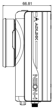
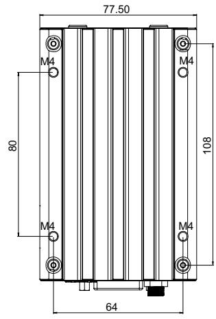
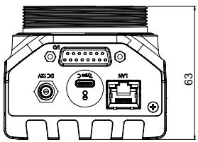
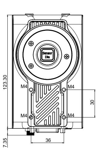
<table><tr><td></td><td>NEON-201B-JT2</td><td>NEON-202B-JT2</td><td>NEON-203B-JT2</td><td>NEON-204B-JT2</td></tr><tr><td>Processor</td><td colspan="4">NVIDIA® JetsonTM TX2</td></tr><tr><td>Display Output</td><td colspan="4">DisplayPort from Type-C, 1920x1080 @ 30fps</td></tr><tr><td>Image Sensor Resolution</td><td>1280x960</td><td>1600x1200</td><td>1920x1080</td><td>2592x1944</td></tr><tr><td>Image Sensor Size</td><td>1/3&quot;</td><td>1/1.8&quot;</td><td>1/3.7&quot;</td><td>1/2.5&quot;</td></tr><tr><td>Frame Rate (fps)</td><td>54</td><td>60</td><td>30</td><td>14</td></tr><tr><td>Shutter</td><td colspan="2">Global</td><td colspan="2">Rolling</td></tr><tr><td>Color/Mono</td><td colspan="4">Color</td></tr><tr><td>Image Sensor Trigger Mode</td><td colspan="4">External trigger (see note below), software trigger, free run</td></tr><tr><td>Digital Input</td><td colspan="4">4x DI, includes 1x sensor trigger</td></tr><tr><td>Digital Output</td><td colspan="4">4x DO, includes 1x strobe out</td></tr><tr><td>UART</td><td colspan="4">TXD, RXD, GND</td></tr><tr><td>Dimensions/Weight</td><td colspan="4">123.3 x 66.81 x 77.5 mm; 700g</td></tr><tr><td>Power Supply</td><td colspan="4">DC power from Type-C connector or DC jack</td></tr><tr><td>USB</td><td colspan="4">1x USB OTG port; 1x USB3 and 1x USB2 from Type-C connector</td></tr></table>

![The image shows a simple icon of a white document with a folded upper-right corner. Horizontal grey lines run across the document, resembling lined paper. A large, bold red checkmark is superimposed over the center of the document.](.neon-2000-jt2-50-1z313-2020-12/84677c815391af07f9597bd8cb1f32173b1c1e366cf4876482a9e1d29d76c0d6.jpg)
NOTE:

Under External Trigger Mode, the sensor exposure time can be based on the preset time in Pylon.

# 1.4 Mechanical Dimensions

This section provides dimensions and related mechanical information for the NEON-2000-JT2.

# 1.4.1 Camera Dimensions
![Sensor Die\nM4\nM4\nM4\n30\n7.35\n36](.neon-2000-jt2-50-1z313-2020-12/8e6e0c9e5d8ee0f1e4041c2cf9fcb33b0b7f0626be1bf2cb7a4d7ee6ef2366db.jpg)

![66.81\nADLINK\nNEON-1](.neon-2000-jt2-50-1z313-2020-12/94356593cf9c7e748c6081f5f611ef02f48cb9d9b566b7881db2624dc7b5869d.jpg)

![77.50\nM4\nM4\n80\n108\nM4\nM4\n64](.neon-2000-jt2-50-1z313-2020-12/a274e1f28e01338b1afcdccec489b91a90cd3bea17a6b555deb516186192052f.jpg)

![Q1\nAS130\n3x80\n8\nMT1\n63](.neon-2000-jt2-50-1z313-2020-12/44db55618e0a7359826bba6fb940152cd89d12fc474333c06ecf5d6648e37d19.jpg)

Dimensions: mm

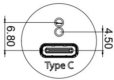
# 1.4.2 USB Type-C Screw Lock Location and Dimensions
![6.80\nType C\n4.50](.neon-2000-jt2-50-1z313-2020-12/a91198fd6c37c8164ff555dc85bbddbd66555e23496de2629403feb206f6c999.jpg)

Dimensions: mm

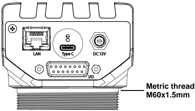
# 1.4.3 LED Light Mounting Thread
![LAN\nType C\nDC 12V\nI/O\nMetric thread\nM60x1.5mm](.neon-2000-jt2-50-1z313-2020-12/f289d3de84ebaafbef7d128d90fff6565071ebfe827d9dbf892e98861d552fab.jpg)

# 2 Connectors and I/O

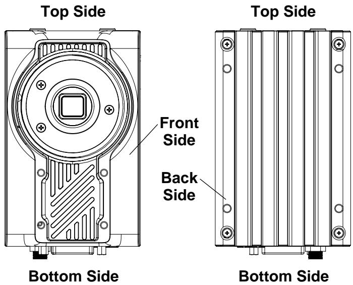
This chapter includes the locations and descriptions of the connectors and I/O found on the NEON-2000-JT2.
![Top Side\nFront Side\nBack Side\nBottom Side\nTop Side\nBottom Side](.neon-2000-jt2-50-1z313-2020-12/22487bcfb695794ff84c1ef26c5c542ac4ea3b7df90393b59f942680f2b7994c.jpg)

Figure 2-1: NEON-2000-JT2 Orientation

# 2.1 Bottom Side I/O and Connector Description
![3\nLAN\n2\nType C\n1\nDC 12V\n4\nI/O](.neon-2000-jt2-50-1z313-2020-12/5c5286bc19e999416916cba5797f2e3087731ee2f08865ca0da60a788a80aa8a.jpg)

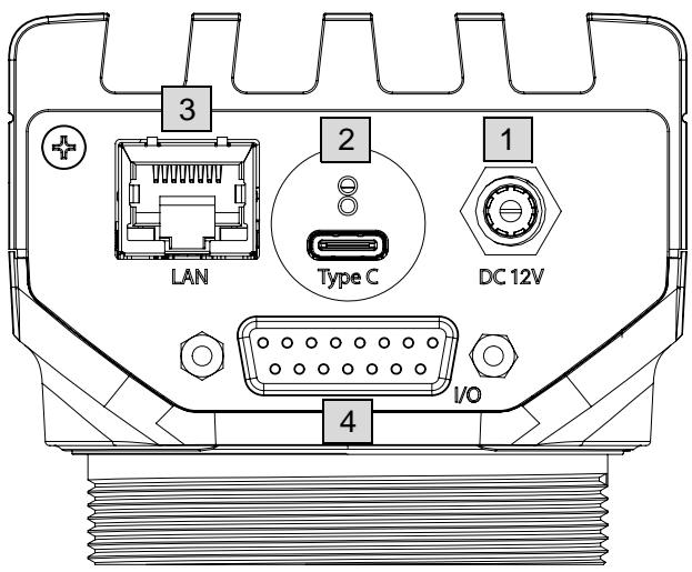
Figure 2-2: Bottom Side I/O and Connectors

<table><tr><td>Item</td><td>Description</td></tr><tr><td>1</td><td>DC Jack for DC input with included ADLINK AC/DC adaptor (P/N 31-62156-1000-A0)Power input: 12V DC at &gt;30 W</td></tr><tr><td>2</td><td>USB Type-C connector w/ screw lockSupports DisplayPort (up to 1080P @ 30 fps)The NEON-2000-JT2 can be powered via this port or the DC jack</td></tr><tr><td>3</td><td>1 GbE LAN at 10/100/1000 Mbit/s</td></tr><tr><td>4</td><td>15-pin D-sub I/O connector for the digital I/O and UART. Use to connect external I/O devices such as sensors, COM and LED/strobe controllers.</td></tr></table>

Table 2-1: Bottom Side I/O and Connectors

# 2.1.1 D-sub I/O Connector

![8\n1\n15\n9](.neon-2000-jt2-50-1z313-2020-12/c0966ebf3f2d64636fd771874dea70cc184740abda1abe7cf5e35f664fb8c284.jpg)

Figure 2-3: D-sub I/O Connector

<table><tr><td>Pin</td><td>Function</td><td>Pin</td><td>Function</td></tr><tr><td>1</td><td>UART - TX</td><td>2</td><td>DI/O GND</td></tr><tr><td>3</td><td>Digital output 0/Strobe output 0 (see note 2)</td><td>4</td><td>Digital output 1</td></tr><tr><td>5</td><td>Digital output 2</td><td>6</td><td>Digital output 3</td></tr><tr><td>7</td><td>UART GND</td><td>8</td><td>Reserved</td></tr><tr><td>9</td><td>UART – RX</td><td>10</td><td>DI/O GND</td></tr><tr><td>11</td><td>Digital input 0/Trigger input 0 (see note 1)</td><td>12</td><td>Digital Input 1</td></tr><tr><td>13</td><td>Digital Input 2</td><td>14</td><td>Digital Input 3</td></tr><tr><td>15</td><td>Reserved</td><td></td><td></td></tr></table>

Table 2-2: D-sub I/O Connector Pin Definitions

![The image displays an icon featuring a white document with a folded top-left corner. Faint horizontal gray lines run across the paper, suggesting a form or list. A large, bold red checkmark is superimposed over the center of the document. The entire graphic is enclosed within a black rectangular border.](.neon-2000-jt2-50-1z313-2020-12/8dcf10229946b293be50ae162164e98d84d565f334107636226855f4e20e7f09.jpg)
NOTE:

1. Pin 11 (Digital input 0/Trigger input 0) is programmable. When configured for trigger input, it is used for hardware triggering of the image sensor. Connect an external sensor signal to pin 11 and set the camera to hardware trigger mode to enable realtime or hardware triggered image capture.
2. Pin 3 (Digital output 0/Strobe output 0) is programmable. When configured for strobe output, it can be connected to an LED light/strobe controller to adjust the timing latency/delay according to the camera connected to pin 11.

<table><tr><td>I/O Category</td><td>Maximum Throughput</td><td colspan="3">Specification</td></tr><tr><td>UART</td><td>-</td><td colspan="3">Baud rate: 9600bps @ 8N1</td></tr><tr><td rowspan="4">Digital Input</td><td rowspan="4">10 KHz</td><td>Common sharing:</td><td colspan="2">1 common for sharing ground</td></tr><tr><td>Input range:</td><td colspan="2">0-5 VDC</td></tr><tr><td>High level threshold:</td><td colspan="2">2-5 VDC</td></tr><tr><td>Low level threshold:</td><td colspan="2">0-0.8 VDC</td></tr><tr><td rowspan="2">Digital Output</td><td rowspan="2">10KHz</td><td rowspan="2">Open-collector</td><td>Input voltage range:</td><td>3.3-30 VDC</td></tr><tr><td>Maximum sink current</td><td>100 mA</td></tr></table>

Table 2-3: D-sub I/O Connector Specification

# 2.2 Top Side I/O and Connector Description

![5\nPower\n6\nStatus\n7\nSD\n8\nMicro USB\n9](.neon-2000-jt2-50-1z313-2020-12/eb722af8feb5c32756cf16852a1f84bc34e30e91eb9458c0e82b75e08aa1b4d2.jpg)

Figure 2-4: Top Side I/O and Connectors

<table><tr><td>Item</td><td>Description</td></tr><tr><td>5</td><td>Power status LED. Lights green when power is connected.</td></tr><tr><td>6</td><td>Operating system status LED. Flashes orange when the system is booting, and lights when the system has booted successfully.</td></tr><tr><td>7</td><td>microSD card slot for additional storage. An optional 32 GB microSD card is available from ADLINK. (P/N 29-F0500-1020)</td></tr><tr><td>8</td><td>Wafer connector. This connector is used to update the NEON-2000-JT2. See “System Flash” on page 39.</td></tr><tr><td>9</td><td>Micro-USB port. This connector is used to update the NEON-2000-JT2. See “System Flash” on page 39.</td></tr></table>

Table 2-4: Top Side I/O and Connectors

# 2.2.1 Wafer Connector

![9\n1\n10\n2](.neon-2000-jt2-50-1z313-2020-12/8972fcf7f7de9a1a0d9c827028779818e54f0bf4028f8a15fee77382effb96be.jpg)

Figure 2-5: Wafer Connector

<table><tr><td>Pin</td><td>Function</td><td>Pin</td><td>Function</td></tr><tr><td>1</td><td>Reserved</td><td>2</td><td>Reserved</td></tr><tr><td>3</td><td>System Reset</td><td>4</td><td>GND</td></tr><tr><td>5</td><td>RECOVERY</td><td>6</td><td>GND</td></tr><tr><td>7</td><td>POWER Button</td><td>8</td><td>GND</td></tr><tr><td>9</td><td>CHARGER PRSNT</td><td>10</td><td>GND</td></tr></table>

Table 2-5: Wafer Connector Pin Definitions

# 2.3 Front Side I/O and Connector Description

![10\n11](.neon-2000-jt2-50-1z313-2020-12/81c0eb220ab4e0e006aad59cb1d9c2015da77efda28b3e6d777bcdb41b02a32a.jpg)

![12\n1\n2\n3\n4\n5\n6\n7\n8\n9\n10\n11\n12\n13\n14\n15\n16\n17\n18\n19\n20\n21\n22\n23\n24\n25\n26\n27\n28\n29\n30\n31\n32\n33\n34\n35\n36\n37\n38\n39\n40\n41\n42\n43\n44\n45\n46\n47\n48\n49\n50\n51\n52\n53\n54\n55\n56\n57\n58\n59\n60\n61\n62\n63\n64\n65\n66\n67\n68\n69\n70\n71\n72\n73\n74\n75\n76\n77\n78\n79\n80](.neon-2000-jt2-50-1z313-2020-12/3b5a2dba7c951b1924a59efc6162e6fb42f486cb825cf604c102bb03c4c9aa0e.jpg)

Figure 2-6: Front Side I/O and Connectors

<table><tr><td>Item</td><td>Description</td></tr><tr><td>10</td><td>C-type lens mount</td></tr><tr><td>11</td><td>Image sensor</td></tr><tr><td>12</td><td>Strobe/LED light mounting thread. See “LED Light Mounting Thread” on page 6.</td></tr></table>

Table 2-6: Front Side I/O and Connectors

This page intentionally left blank.

# 3 Getting Started

# 3.1 Mounting

The NEON-2000-JT2 can be mounted using the mounting screw holes on either the front (A) or back (B) sides.

Le NEON-2000-JT2 peut être monté à l'aide des trous de vis de montage sur les côtés avant (A) ou arrière (B).

![Sensor Die\nA23.30\n30\n36\nA: 4x M\n4x vi](.neon-2000-jt2-50-1z313-2020-12/52f5b5020ceebef22d12881d7cbe4ca5b0e5bf22ebe0c25c01c9471184d44124.jpg)

M4 screws, L=6mm4x vis M4, L=6mm

![64\n80\n108\nB: 4\n4\n64](.neon-2000-jt2-50-1z313-2020-12/d9ae7060b0f1487b8539c6f0d3ea17e47227d52d27d28ed4a3b23f2d7689b0d8.jpg)

x M4 screws, L=6mmx vis M4, L=6mm

Figure 3-1: NEON-2000-JT2 Mounting Holes

# 3.2 Digital I/O Connection Example

External devices such as trigger sensors, LED light controllers or relays can be connected to the NEON-2000-JT2 to implement different applications. This section shows an example of how to connect such devices.

![Camera side\nVDD\n470 ohm\nphotocoupler\ncontrol circuit\nMax 5 V\nDI/O GND](.neon-2000-jt2-50-1z313-2020-12/aefcc9b45f68387ac6771a898382efbe0f064a2fc58a0b4ca9932a1074dab7a8.jpg)

Figure 3-2: Digital Input Schematic Diagram

![Camera side\nPTC\nresettable fuse\nDO 0-3\nMax. 100 mA\nload\ncontrol circuit\nDC\nMax. 30 V\nDI/O GND](.neon-2000-jt2-50-1z313-2020-12/1510450be95f7040a248b96486e03fdac2b67df0d8442418b63309918b0c6b8a.jpg)

Figure 3-3: Digital Output Schematic Diagram

# 3.3 Attaching a Lens

The NEON-2000-JT2 is compatible with C-mount type lenses.

![Transfer Ring\nLens\nWasher](.neon-2000-jt2-50-1z313-2020-12/19c55c168c3b04f2be9fabd6ef6d7d9e2f6d9f2d70259a8618ca316a9dc4ed93.jpg)

Figure 3-4: Lens Attachment Assembly

![The image features a white document icon with a folded top-left corner. Faint grey horizontal lines run across the page, suggesting text, while a large, bold red checkmark is superimposed diagonally over the center.](.neon-2000-jt2-50-1z313-2020-12/3e3038750f9f8cc7510c09fb7fa633544bcb3a17f4016a88dfc0cfaac8539319.jpg)
NOTE:

The transfer ring is installed before shipping. The washer is used only with the NEON-202B-JT2.

# 3.4 Power and Peripheral Connections

The NEON-2000-JT2 DC power source can be either from a USB Type-C adaptor or DC jack. The USB Type-C connector also supports a DisplayPort video signal and USB3, which can be used to connect a keyboard and mouse. The following figures show examples of possible power and peripheral connection configurations.

![Based on the provided flowchart, here are the labeled blocks and their connections:\n\n*   **Keyboard & Mouse** connects via **USB** to **Type C Hub**.\n*   **Type C Hub** connects via **HDMI** to **Monitor**.\n*   **Type C Hub** connects via **Type C** to the **Type C** port on the device graphic at the bottom.\n*   **AC Power** connects to **AC/DC Adapter**.\n*   **AC/DC Adapter** connects to the **DC 12V** port on the device graphic.\n\nThe device graphic at the bottom also contains labels for **LAN** and **IO**.](.neon-2000-jt2-50-1z313-2020-12/77b79066d0f6827bae0ea4d7083f36e876d3f4db242bb2f002f63de2b2cfcb8e.jpg)

![The image shows a white icon resembling a document or sheet of paper with a folded top-right corner and faint horizontal lines. A large, bold red checkmark is overlaid on top of the document.](.neon-2000-jt2-50-1z313-2020-12/937cc7ed7e5a245e0732e325a2ddbad3b5a54e5ca065f2a243d3c95dffc5e160.jpg)
NOTE:

This configuration requires an ADLINK AC/DC power adapter (P/N 31-62156-1000-A0).

Figure 3-5: Separate Power and Peripheral Connections

![Based on the provided image, here is the description of the flowchart and block diagram:\n\n**Labeled Blocks and Illustrations:**\n*   **Keyboard & Mouse** (Top block)\n*   **AC Power** (Left block)\n*   **Type C Adapter/Hub** (Central block)\n*   **Monitor** (Right block)\n*   **Device Illustration** (Bottom section showing ports labeled: **LAN**, **Type C**, **DC 12V**, and **IO**)\n\n**Connections:**\n*   **Power Cord**: Connects **AC Power** to the **Type C Adapter/Hub**.\n*   **USB**: Connects the **Type C Adapter/Hub** to **Keyboard & Mouse**.\n*   **HDMI**: Connects the **Type C Adapter/Hub** to the **Monitor**.\n*   **Type C**: Connects the **Type C Adapter/Hub** down to the port labeled **Type C** on the bottom device illustration.](.neon-2000-jt2-50-1z313-2020-12/9b859d01e00f7a6cc1b2317ed86128c5f7afc46dea43644d120efa198b431889.jpg)

![The image displays a white document icon with horizontal gray lines running across the page. A large, bold red checkmark is superimposed diagonally over the center of the document. The top left corner of the paper is slightly curled.](.neon-2000-jt2-50-1z313-2020-12/6ad0fca98fa5397613445404333281f60af2c0440ef557551c554b978cb02c38.jpg)
NOTE:

This configuration requires an ADLINK USB Type-C hub/adapter (P/N 92-99090-1010).

Figure 3-6: Combined Power and Peripheral Connections

# 3.5 Image Capture and Inference

ADLINK provide sample files for testing the NEON-2000-JT2 image capturing and inference functions. The following steps illustrate how to execute the Classification Sample with the NEON-2000-JT2.

Step 1: Right-click the Capture\_and\_inference\_Sample folder on the desktop and select Open in Terminal.

![Open\nReturn\nOpen In New Tab\nCtrl+Return\nOpen In New Window\nShift+Return\nOpen With Other Application\nCut\nCtrl+X\nCopy\nCtrl+C\nMove to...\nCopy to...\nMove to Trash\nDelete\nResize Icon...\nRename...\nF2\nCompress...\nLocal Network Share\nOpen in Terminal\nSend to...\nRevert to Previous Version...\nProperties\nCtrl+I\nCapture_and_Inference_Sample](.neon-2000-jt2-50-1z313-2020-12/71f5dffd5cb55cfc1a95881f912301575ee5c5fb8089294d22e4f08b597dcb41.jpg)

Step 2: Execute the sample by entering the command ./build/ aarch64/bin/imagenet-camera [Sensor\_width] [Sensor\_height]. Sensor\_width and Sensor\_height are parameters dependent on the camera model and sensor settings. For example, for the NEON-202B-JT2, the command would be: ./ build/aarch64/bin/imagenet-camera 1600 1200.

![nvidia@nvidia-desktop:~/Desktop/Capture_and_Inference_Sample\nla@nvidia-desktop:~/Desktop/Capture_and_Inference_Sample\$ ./build/aarch64/bin/Imagenet-camera 1600 12](.neon-2000-jt2-50-1z313-2020-12/159c53531016c2c58841cd367685b40c2f119b6f44f3c70e99f3f4548a3129fa.jpg)

The Sensor\_width and Sensor\_height settings can also be set via PylonViewer.

![pylon Viewer 64-Bit\nFile View Camera Tools ?\nDevices\nGigE\nUSB\nBasler daA1600-60uc (23148129)\nFeatures (Basler daA1600-60uc (23148129))\nSearch (Ctrl+F)\nFeature	Value\nFavorites\nAdd favorites by right-clicking a feature below.\nBasler daA1600-60uc (23148129)\nAnalog Control\nImage Format Control\nSensor Width	1600\nSensor Height	1200\nWidth Max	1600\nHeight Max	1200\nWidth	1600\nHeight	1200\nOffset X	0\nOffset Y	0\nBinning Horizontal Mode	Sum\nBinning Horizontal	1\nBinning Vertical Mode	Sum\nBinning Vertical	1\nReverse X\nReverse Y\nUser Level:	Guru	Show Unavailable Favorites	 Polling](.neon-2000-jt2-50-1z313-2020-12/cf63cba410535d12852df4417dc3ab94ef89ee45c4d0061bab436289c35d4297.jpg)

Step 3: Captured image and Inference results are displayed with the inference result shown at the left-top corner of the image.

![98.05% mouse, computer mouse\nClass: 0673 - 0.003717 (mouse, co\nmagnet-camera: 98.3716% class\nCamera: OnImagegrabbed frame num\nCamera: WIDTH 1000, Height 1200,\nCamera: buffer address OnTime\nCamera: OnImagegrabbed frame num\nCamera: WIDTH 1000, Height 1200,\nCamera: buffer address OnTime\nClass: 0673 - 0.003761 (mouse, co\nmagnet-camera: 98.6181% class\nCamera: OnImagegrabbed frame num\nCamera: WIDTH 1000, Height 1200,\nCamera: buffer address OnTime\nClass: 0673 - 0.004661 (mouse, co\nmagnet-camera: 98.6460% class\nCamera: OnImagegrabbed frame num\nCamera: WIDTH 1000, Height 1200,\nCamera: buffer address OnTime\nCamera: Width 1000, Height 1200,\nCamera: buffer address OnTime\nClass: 0673 - 0.988171 (mouse, co\nmagnet-camera: 98.8174% class](.neon-2000-jt2-50-1z313-2020-12/414d74a8e3e3cd318eca5b90146e4876e1a7b5f8a5e2ef865ba7b23b368e82e3.jpg)

# 3.5.1 Inference Concepts and Sample

This section illustrates the main concepts of inference with sample files and also provides a link to examples from NVIDIA. The default path of the sample is /home/adlink/Desktop/

Capture\_and\_ Inference\_Sample.

Take special notice of the following important files:

X System requirements and sample build-up procedures ../Capture\_and\_Inference\_Sample /README.md
X Pre-training model for image classification ../Capture\_and\_Inference\_Sample/data/networks
X Sample code ../Capture\_and\_Inference\_Sample/examples/imagenetcamera
X Capturing images with a Basler camera ../Capture\_and\_Inference\_Sample/utils/camera/indCamera
X Execution file ../Capture\_and\_Inference\_Sample/build/aarch64/bin/imagenet-camera

To learn more about image sensors, samples and documents are included in /opt/pylon5. For more samples relating to image inference, NVIDIA provides examples at https://github.com/dusty-nv/ jetson-inference.

# 3.5.2 Sample Inference Steps

Use these steps to set up a streaming camera and to display and classify an image inference.

Step 1: Create a camera

ADLINK provides indcamera.cpp and indcamera.h which package several PYLON APIs for developers to create custom applications for the NEON-2000-JT2.

Step 2: Create an ImageNet

Create an inference model before using it. This sample takes ImageNet for example.

Step 3: Start streaming

In this sample, the NEON-2000-JT2 is in free run mode and frames are passed one at a time. Make sure the pixel format of the camera output is set to RGB mode, configured by /opt/pylon5/ bin/PylonViewerApp: Feature > Basler [Product Name] > Image Format Control > Pixel Format > RGB8.

Step 4: Classify the image

The image source can be defined as either from the NEON-2000- JT2 or storage media. The following commands will result in errors if the NEON-2000-JT2 sensor is still connected to PylonViewer-App. If an error occurs, disconnect the camera by clicking Close Camera in PylonViewerApp:

```txt
./build/aarch64/bin/imagenet-camera [input_width]
[input_height]

./build/aarch64/bin/imagenet-console [input_image]
[output_image]
```

Step 5: Update the display

Draw frames and inference result by OpenGL.

# 3.6 Use Pylon to capture and adjust the sensor

This section describes how to use the Basler Pylon utility to capture an image, set the sensor, and load/save the sensor settings.

# 3.6.1 Capture an Image via Pylon

The following steps illustrate how to capture images using the Basler PylonViewerApp.

Step 1: Click Files.

![Ubuntu Desktop\nFiles Web](.neon-2000-jt2-50-1z313-2020-12/5782fce1b187850c220a06263f8686487063d9d0192d87854428dfbfe9967d27.jpg)

Step 2: Go to /opt/pylon5/bin and double-click PylonViewerApp, or, select the PylonViewerApp in the launcher.
![bin\nRecent\nHome\nDesktop\nDocuments\nDownloads\nMusic\nPictures\nVideos\nTrash\nNetwork\nComputer\nConnect to Server\nlibQt5XcbQpa.so\nlibQt5XcbQpa.so.5\nlibQt5XcbQpa.so.5.6\nlibQt5XcbQpa.so.5.6.2\nlibQt5Xml.so\nlibQt5Xml.so.5\nlibQt5Xml.so.5.6\nlibQt5Xml.so.5.6.2\npylon-config\nPylonFirmwareUpdater\npylon-setup-env.sh\npylon-start-with-logging\nPylonViewerApp\nStartPylonViewerWithLogging.sh\n'PylonViewerApp' selected (833.4 kB)](.neon-2000-jt2-50-1z313-2020-12/dd76cf060370c4fd2d8d7fadf5ffa50b69fbd5b3be520a54197b98ba6a7cbab0.jpg)

Step 3: Double-click Basler daA1600-60c to open the camera.
![pylon Viewer 64-Bit\nFile View Camera Tools ?\nDevices\nGigE\nUSB\nBasler diaA1600-60uc (22745174)\nTip: Double-click a camera to open it. ✓ Auto-Scan\nFeatures\nSelect any open camera in the Devices pane to display its features.](.neon-2000-jt2-50-1z313-2020-12/05f4dfd4fa61a90e8bbef3266ea1d652ba50d09522f1895f45b38847fab7fbaa.jpg)

![pylon Viewer 64-Bit\nFile View Camera Tools ?\nDevices\nGigE\nUSB\nBasler daA1600-60uc (22745174)\nFeatures (Basler daA1600-60uc (22745174))\nSearch (Ctrl+F)\nFeature	Value\nFavorites\nAdd favorites by right-clicking a feature below.\nBasler daA1600-60uc (22745174)\nTransport Layer\nStream Parameters\nImage Format Conversion](.neon-2000-jt2-50-1z313-2020-12/0c9a6ba75b04a8aa396ccfe149577e9cd7069cbddcf57ed6798ff36b4bb99af5.jpg)

![The image displays a white piece of lined paper with a folded upper-left corner. A large red checkmark is drawn diagonally across the document, extending from the bottom left to the top right.](.neon-2000-jt2-50-1z313-2020-12/1e726cc7ae24af6e149450d4faec5584162fdc02576cc26e70612c4855676f67.jpg)
NOTE:

Basler daA1600-60c is the specific sensor for the NEON-202B-JT2 used in this example. As sensor names are model-specific, be sure to select the correct sensor based on the specific NEON-2000-JT2 used.

Step 4: Click Continuous Shot to begin capturing images.
![pylon Viewer 64-Bit\nFile View Camera Tools ?\nFeatures (Basler daA1600-60uc (22487449))\nSearch (Ctrl+F)\nFeature	Value\nFavorites\nAdd favorites by right-clicking a feature below.\nBasler daA1600-60uc (22487449)\nTransport Layer\nStream Parameters\nImage Format Conversion](.neon-2000-jt2-50-1z313-2020-12/f25738d0187680a1b092d9600b1fe66b654ff51a830bba0a028be1ea5da11070.jpg)

![pylonViewer 64-bit\nFile View Camera Tools ?\nDevices\nGrpt\nUSB\nBasler daA1600-68uc (22745174)\nFeatures (Basler daA1600-68uc (22745174))\nFeature Value\nFavorites\nAuto Scan\nBasler daA1600-68uc (22745174)\nTransport Layer\nStream Parameters\nImage Format Conversion\nUser Level: Guru Show Unavailable Favorites Pingling\nBasier daA1600-68uc (22745174)\nADLINK\nNEON-T\n41.7 fps (360.3 MHz) Images: 7.6KB, Errors: 0 1600 x 1200 50 %\nMessage Log\nLevel Time Source Message\nInformation 2018-12-19 03:29:29.230 Basier daA1600-68uc (22745174)\nInformation 2018-12-19 03:29:02.587 Basier daA1600-68uc (22745174)\nInformation 2018-12-19 03:28:58.676 Basier daA1600-68uc (22745174)\nInformation 2018-12-19 03:28:58.319 python Viewer Continuous shot on 'Basier daA1600-68uc (22745174)' has been started.\n'Basier daA1600-68uc (22745174)' has been opened.\n'Basier daA1600-68uc (22745174)' has been detected.\npython Viewer 5.0.9.10389 64-bit has been started.](.neon-2000-jt2-50-1z313-2020-12/8b5637a8b33f9e704b6d9c111f47df1730322eb0aed0f571da04eab87722d8b6.jpg)

# 3.6.2 Image Sensor Adjustment via Pylon

The default NEON-2000-JT2 sensor settings may not be suitable for all applications. This section illustrates how to customize the sensor settings.

# 3.6.2.1 Use Pylon utility to load saved sensor configuration files

Step 1: Click Files.

![Ubuntu Desktop\nFiles Web](.neon-2000-jt2-50-1z313-2020-12/328097b0eac9fe9531884b6dabd17a946c8f4cb2b5d39418960ad1920b772ee7.jpg)

Step 2: Go to /opt/pylon5/bin and double-click PylonViewerApp, or, select the PylonViewerApp in the launcher.

![bin\nRecent\nHome\nDesktop\nDocuments\nDownloads\nMusic\nPictures\nVideos\nTrash\nNetwork\nComputer\nConnect to Server\nlibQt5XcbQpa.so\nlibQt5XcbQpa.so.5\nlibQt5XcbQpa.so.5.6\nlibQt5XcbQpa.so.5.6.2\nlibQt5Xml.so\nlibQt5Xml.so.5\nlibQt5Xml.so.5.6\nlibQt5Xml.so.5.6.2\npylon-config\nPylonFirmwareUpdater\npylon-setup-env.sh\npylon-start-with-logging\nPylonViewerApp\nStartPylonViewerWithLogging.sh\n'PylonViewerApp' selected (833.4 kB)](.neon-2000-jt2-50-1z313-2020-12/ef03861a8a9b5788f110bbaa476e75d2df7df3e7b2148407f0389adce5f30f3c.jpg)

Step 3: Double-click Basler daA1600-60c to open the camera.
![pylon Viewer 64-Bit\nFile View Camera Tools ?\nDevices\nGigE\nUSB\nBasler diaA1600-60uc (22745174)\nTip: Double-click a camera to open it. ✓ Auto-Scan\nFeatures\nSelect any open camera in the Devices pane to display its features.](.neon-2000-jt2-50-1z313-2020-12/4c2175a089a3debaad5e13fa68c76e16213b017621181ddb58eae191880c223b.jpg)

![pylon Viewer 64-Bit\nFile View Camera Tools ?\nDevices\nGigE\nUSB\nBasler daA1600-60uc (22745174)\nFeatures (Basler daA1600-60uc (22745174))\nSearch (Ctrl+F)\nFeature	Value\nFavorites\nAdd favorites by right-clicking a feature below.\nBasler daA1600-60uc (22745174)\nTransport Layer\nStream Parameters\nImage Format Conversion](.neon-2000-jt2-50-1z313-2020-12/2d53f8fe73c76445b9bb2fe1f93ce5d6cb7d5ea6da463807b5124f9eeb56021f.jpg)

![The image displays a graphic icon featuring a white document or piece of paper with a folded top-right corner. Faint horizontal lines run across the paper, suggesting text. Overlaid on the document is a large, bold red checkmark that spans diagonally from the bottom left to the top right.](.neon-2000-jt2-50-1z313-2020-12/f57308fb470c6597f5499c239306cf7a60b6d414c52ab9ca734be99fcc613344.jpg)
NOTE:

Basler daA1600-60c is the specific sensor for the NEON-202B-JT2 used in this example. As sensor names are model-specific, be sure to select the correct sensor based on the specific NEON-2000-JT2 used.

Step 4: Files with image sensor settings can be loaded by selecting Load Features… and choosing the appropriate .pfs file.

![pylon Viewer 64-Bit\nFile View\nCamera Tools ?\nOpen Ctrl+O\nClose Ctrl+L\nSingle Shot F6\nContinuous Shot F7\nStop F8\nAutomatic Image Adjustment\nLoad Features...\nSaye Features...\nFile Access...\nAdd Remote GigE Camera... F12](.neon-2000-jt2-50-1z313-2020-12/66a9b78a24b138a67d0d8abbb1e882a98cba4670b4cd5874625fd2d29caa5007.jpg)

![Load File\nLook in: /home/adlink\nComputer\nadlink\nName	Size	Type	Date Modified\nDesktop	Folder	15 Jan ...5:27:01\nDocuments	Folder	13 Jan ...6:22:03\nDownloads	Folder	13 Jan ...6:22:03\ngenicam_xml_cache	Folder	14 Jan ...3:12:03\nMusic	Folder	13 Jan ...6:22:03\nPictures	Folder	5 Mar ...02:17\nPublic	Folder	13 Jan ...6:22:03\nTemplates	Folder	13 Jan ...6:22:03\nVideos	Folder	13 Jan ...6:22:03\nVisionWorks-SFM-0.90-Samples	Folder	13 Jan ...6:52:13\ndaA1280-54uc_demo.pfs	2 KB pfs File	10 Jan ...9:30:19\ndaA1600-60uc_demo.pfs	2 KB pfs File	10 Jan ...9:30:19\ndaA1920-30uc_demo.pfs	3 KB pfs File	19 Feb ...6:23:16\ndaA2500-14uc_demo.pfs	2 KB pfs File	10 Jan ...9:30:19\nFile name: daA1920-30uc_demo.pfs\nFiles of type: Pylon Feature Stream (*.pfs)\nOpen\nCancel](.neon-2000-jt2-50-1z313-2020-12/d96e04a6c9b2d479c5b642d4aefa23f45b637ca9f4e2384b4a6057be9455e0d0.jpg)

Step 5: If the file loads successfully, the sensor’s settings should be modified. For example:

![Gain Auto\nOff\nExposure Auto\nOff\nLight Source Preset\nOff\nBalance White Auto\nOff\nColor Space Mode\nRGB](.neon-2000-jt2-50-1z313-2020-12/80c09408ad602104e15d03b7314b835d3417c504f6e17b603f3332a4217744d1.jpg)

The modified settings can also be viewed under Features in pylon Viewer.

![pylon Viewer 64-Bit\nFile View Camera Tools ?\nDevices\nGigE\n✓ USB\nBasler daA1600-60uc (22745174)\nAuto-Scan\nFeatures (Basler daA1600-60uc (22745174))\nSearch (Ctrl+F)\nFeature	Value\n▶ Favorites\n▼ Basler daA1600-60uc (22745174)\n▼ Analog Control\nGain Selector	All\nGain (dB)	0.0\nGain Auto	Off\nAuto Gain Lower Limit ...	0.0\nAuto Gain Upper Limit ...	24.014275\nBlack Level Selector	All\nBlack Level (DN)	0.0\nGamma	1.0\nColor Space Mode	RGB\n▶ Image Format Control\n▼ Acquisition Control\nSensor Shutter Mode	Global\nOverlap Mode	On\nExposure Time (ug)	30000.0\nUser Level:	Guru	✓ Show Unavailable Favorites	✓ Polling](.neon-2000-jt2-50-1z313-2020-12/afae6fb18bc523a9c28265834f93c79bbbdf4f20241289459020646b6c2ec5af.jpg)

Step 6: Click Continuous Shot to have the camera capture images with the loaded sensor settings.
![pylon Viewer 64-Bit\nFile View Camera Tools ?\nDevices\nGigE\nUSB\nBasler daA1600-60uc (22745174)\nAuto-Scan](.neon-2000-jt2-50-1z313-2020-12/3a66bb9767d9d3ea2d3d41679f00298d000c169bdbe795e71bc680f28f7710dc.jpg)

![pylon Viewer 64-Bit\nFile View Camera Tools\nDevices\nOpt\nUSB\nBasler daA1600-60uc (22745174)\nFeatures (Basler daA1600-60uc (22745174))\nFeature Value\nFavorites\nAdd Searches by right-clicking a features system.\nBasler daA1600-60uc (22745174)\nTransport Layer\nStream Parameters\nImage Format Conversion\nBasler daA1600-60uc (22745174)\nADLINK\nNEON T\n41.7 fps (160.3 Mbps) Images: 7.68K Errors: 0 1600 x 1200 50 %](.neon-2000-jt2-50-1z313-2020-12/11613764bdb59bc8d4cb09521d9eee61d55e7a816c3803a659dad3c4d0da673f.jpg)

# 3.6.2.2 Use Pylon to adjust the sensor

Step 1: Click Files.

![Ubuntu Desktop\nFiles Web](.neon-2000-jt2-50-1z313-2020-12/847eabdd776a158c5eabdf4197600db2e909f0fd387559feaab1fb33ff3ff4ec.jpg)

Step 2: Go to /opt/pylon5/bin and double-click PylonViewerApp, or, select the PylonViewerApp in the launcher.

![bin\nRecent\nHome\nDesktop\nDocuments\nDownloads\nMusic\nPictures\nVideos\nTrash\nNetwork\nComputer\nConnect to Server\nlibQt5XcbQpa.so\nlibQt5XcbQpa.so.5\nlibQt5XcbQpa.so.5.6\nlibQt5XcbQpa.so.5.6.2\nlibQt5Xml.so\nlibQt5Xml.so.5\nlibQt5Xml.so.5.6\nlibQt5Xml.so.5.6.2\npylon-config\nPylonFirmwareUpdater\npylon-setup-env.sh\npylon-start-with-logging\nPylonViewerApp\nStartPylonViewerWithLogging.sh\n'PylonViewerApp' selected (833.4 kB)](.neon-2000-jt2-50-1z313-2020-12/49da78e9d7ce963338644dfa2c5a229501ee22a2a5bf774bdae88dce97d0396f.jpg)

Step 3: Double-click Basler daA1600-60c to open the camera.
![pylon Viewer 64-Bit\nFile View Camera Tools ?\nDevices\nGigE\n▼ USB\nBasler daA1600-60uc (22745174)\nFeatures (Basler daA1600-60uc (22745174))\nSearch (Ctrl+F)\nFeature	Value\n▼ Favorites\nAdd favorites by right-clicking a feature below.\n► Basler daA1600-60uc (22745174)\n► Transport Layer\n► Stream Parameters\n► Image Format Conversion](.neon-2000-jt2-50-1z313-2020-12/d96f90d1e11f9b03b7e5e4b0c385d3389ce579ed3c5f6493ec3273d9c732cf5e.jpg)

![The image displays a document icon. It features a white page with a folded top-right corner and faint gray horizontal lines representing text. A large, bold red checkmark is superimposed over the center of the page.](.neon-2000-jt2-50-1z313-2020-12/ba672afddf7b4b0785955d2c1453aebaa255ce1faf03aaaa803b311cbf806a80.jpg)
NOTE:

Basler daA1600-60c is the specific sensor for the NEON-202B-JT2 used in this example. As sensor names are model-specific, be sure to select the correct sensor based on the specific NEON-2000-JT2 used.

Step 4: To save the modified settings to a file, select Camera > Save Features... from the main menu.
![pylon Viewer 64-Bit\nFile View Camera Tools ?\nDevices\nGigE\nUSB\nBasler daA1600-60uc (22745174)\nAuto-Scan\nFeatures (Basler daA1600-60uc (22745174))\nSearch (Ctrl+F)\nFeature	Value\nFavorites\nBasler daA1600-60uc (22745174)\nAnalog Control\nGain Selector	All\nGain (dB)	0.0\nGain Auto	Off\nAuto Gain Lower Limit ...	0.0\nAuto Gain Upper Limit ...	24.014275\nBlack Level Selector	All\nBlack Level (DN)	0.0\nGamma	1.0\nColor Space Mode	RGB\nImage Format Control\nAcquisition Control\nSensor Shutter Mode	Global\nOverlap Mode	On\nExposure Time (us)	20000.0\nUser Level:	Guru	Show Unavailable Favorites	 Polling](.neon-2000-jt2-50-1z313-2020-12/3dbb352f0e59026d6f2697a6be3b2091071fe83df7c20b74e572af9b3b1b0265.jpg)

# 3.6.3 Use APIs to adjust the image sensor

After opening the device, add the PylonFeaturePersistenceLoad function to load features that will adjust the image accordingly.

For example:

```matlab
PylonDeviceOpen( hDev, PYLONC_ACCESS_MODE_CONTROL
    | PYLONC_ACCESS_MODE_STREAM );
PylonDeviceGetNodeMap( hDev, &hMap);
PylonFeaturePersistenceLoad( hMap, "daA1600-
    60uc_adjust image quality.pfs", 1 );
```

```sql
GENAPIC_RESULT PylonFeaturePersistenceLoad ( NODEMAP_HANDLE hMap,
    const char *
    _Bool pFileName,
    verify
)
```

Loadsthefeaturesfromafileand storesit tothenodetree.

# Parameters

[in]hMap Nodemap handle.
[in]pFileName Name of thefile containing the node map values.
[in]verifylfverify==true(default)allnodevalueswillbevalidated

# Returns

If thefunction succeeds,the return value isGENAPI\_E\_OK.

Ifthefunction fails,thereturn value willbeany oferror codesdescribed inthe section Error Codes.

Loadsthe features fromafileand stores it tothenodetree.

```txt
GENAPIC_RESULT PylonDeviceOpen ( PYLON_DEVICE_HANDLE hDev, int accessMode )
```

Open adevice.

# Parameters

[in]hDev Device handle

[in]accessMode Intended accessmode.You canpassone or more of theflags specified below.

# Returns

Ifthefunction succeeds,thereturn valueis GENAPI\_E\_OK.

IfthefunctionflstheretunvauewillbeanyoferrorcodesdescribedinthesectionrrorCodes

Thisfunctionopensadevice.AdevicemustbeopenedbeforeanyperationscanbeperformedonitTheaccessModeargumentcanbe used torestrict the type ofaccess allowed by thedevice.Thefollowing accessmodesareavailable

·PYLONC\_ACCESS\_MODE\_CONTROL-Allows toreadorwritecameraparameterstoconfigurethecamera.
·PYLONC\_ACCESs\_MoDE\_STREAM-Alowstoread imagedatafromthecamera'streamgrabberobject.
PYLONC\_ACCESs\_MoDE\_EVENT-Allowstoreadeventdatafromthecamera'sstreamgrabberobject.
·PYLONC\_ACCESsMDEEXCLusIVE-AllowsexclusiveaccessWhenthisflagisspecifiednootherapplicationmayaccessthe camera.
·PYLONC\_ACCEss\_MoDE\_MONIToR-AllowsonlyreadaccessThisflagcannotbecombinedwithanyotherflags.Itistypicallyused inMulticast/Broadcast applications with GigE cameras.

Youcanpassoneormoreflags.Ifyoupassmorethanoneflag youcancombinethemusing theoroperator.

```txt
GENAPIC_RESULT PylonDeviceGetNodeMap (PYLON_DEVICE_HANDLE hDev, NODEMAP_HANDLE * phMap)
```

Returntheparameter nodemap for adevice.

# Parameters

```txt
[in] hDev Device handle
[out] phMap Result pointer
```

# Returns

```txt
If the function succeeds, the return value is GENAPI_E_OK.
If the function fails, the return value will be any of error codes described in the section Error Codes.
```

ThisfunctionretusahandleforthenodemapofadeviceIfthedevicedoesnotsupportanodemapaninvalidhandleisetuned

This page intentionally left blank.

# 4 Software Upgrade

Each NEON-2000-JT2 is shipped with Ubuntu and Jetpck preinstalled. ADLINK builds custom flash files to upgrade the NEON-2000-JT2 based on NVIDIA’s release schedule.

# Important Notice

NVIDIA official operating system releases for the Jetson TX2 DEV kit CANNOT be used on the NEON-2000-JT2. Be sure to upgrade the NEON-2000-JT2 with an operating system or flash file ONLY from ADLINK.

DO NOT use the NVIDIA SDK manager to upgrade the NEON-2000-JT2.

# 4.1 System Flash

This section describes the equipment and procedures required to upgrade the NEON-2000-JT2.

# 4.1.1 Equipment for flashing the system

The following table lists the required tools for upgrading the NEON-2000-JT2.

<table><tr><td>Item</td><td>Description</td><td>Note</td></tr><tr><td>1</td><td>1x Host PC</td><td>► Required minimum specification: Intel® CoreTM i3 CPU, 4 GB DDR and 128 GB (or above) SSD/HDD.► Requires Ubuntu Desktop 16.04 or 18.04 installed.</td></tr><tr><td>2</td><td>1x Micro-USB to Type-A USB cable</td><td>► Micro-USB connected to NEON-2000-JT2 and Type-A connected to Host PC.► Use USB3 compliant cable for the best performance</td></tr><tr><td>3</td><td>System Flash Cable</td><td>&lt;img src="images/745c2243b36857cbb58f9e751047b27029fb504deaba8c58d2e831639ec179f0.jpg"/&gt;ADLINK P/N 30-01635-0000-A0</td></tr><tr><td>4</td><td>2x Jumpers</td><td>ADLINK P/N 25-10073-1020</td></tr></table>

![The image displays a white document icon featuring a folded top-right corner and faint horizontal lines. A large red checkmark is superimposed over the document, and the entire graphic is enclosed within a thin black square border.](.neon-2000-jt2-50-1z313-2020-12/7fad7d1cad4522a32150c40b7e6bc938ad6b97a7c775df9c7978ed0990ba7f34.jpg)
NOTE:

Either item 3 or 4 can be used for flashing based on user preference.

# 4.1.2 System flashing procedure

When upgrading the system, use the female wafer connector on the NEON-2000-JT2 top side.

![H-NOEN\nAC/UXK\nTop Side](.neon-2000-jt2-50-1z313-2020-12/e79853471e0b198a6429423eda74fa5c7baac14a86feef8b353880f075af6b4b.jpg)

![Power Status\nSD\n#9 #1\n#10 #2\nMicro USB](.neon-2000-jt2-50-1z313-2020-12/31de118f472cdfc674cbc3b4680a785af5ba61adf1f3691aac3c056a445b2130.jpg)

<table><tr><td>Pin</td><td>Function</td><td>Pin</td><td>Function</td></tr><tr><td>1</td><td>Reserved</td><td>2</td><td>Reserved</td></tr><tr><td>3</td><td>System Reset</td><td>4</td><td>GND</td></tr><tr><td>5</td><td>RECOVERY</td><td>6</td><td>GND</td></tr><tr><td>7</td><td>POWER Button</td><td>8</td><td>GND</td></tr><tr><td>9</td><td>CHARGER PRSNT</td><td>10</td><td>GND</td></tr></table>

Table 4-1: Wafer Connector Pin Definitions

Follow these steps flash the NEON-2000-JT2.

Step 1: Request the correct image file from ADLINK and save it to the Host PC.

Step 2: Power on the NEON-2000-JT2 and wait until the Status LED lights orange, but is not flashing.

Step 3: Connect the NEON-2000-JT2 to the Host PC with the Micro-USB to USB Type-A cable.

Step 4: Enter Recovery Mode either by using a jumper or the system flash cable.

Step 5: Short pins 5 and 6 on the wafer connector and wait until the Status LED is flashing.

Pins 5 and 6 can be shorted either by using the jumper, or connecting the system flash cable, then pressing and holding the black button.

Step 6: Short pins 3 and 4 for two seconds, then release.

Pins 3 and 4 can be shorted either by using the jumper, or connecting the system flash cable, then pressing and holding the red button for two seconds before releasing it. The black button can be released after the red button is released.

Step 7: Execute the lsusb command on the Host PC. If NVIDIA Corp. is in the resulting list, the NEON-2000-JT2 has successfully entered recovery mode.

![adlink@adlink-MXC6400: ~\nFile Edit View Search Terminal Help\nHOST PC\nadlink@adlink-MXC6400:~\$ lsusb\nBus 002 Device 001: ID 1d6b:0003 Linux Foundation 3.0 root hub\nBus 001 Device 006: ID 0955:7020 Nvidia Corp.\nBus 001 Device 005: ID 046d:c31c Logitech, Inc. Keyboard K120\nBus 001 Device 004: ID 045e:00cb Microsoft Corp. Basic Optical Mouse v2.0\nBus 001 Device 001: ID 1d6b:0002 Linux Foundation 2.0 root hub\nBus 004 Device 001: ID 1d6b:0003 Linux Foundation 3.0 root hub\nBus 003 Device 002: ID 064f:2af9 WIBU-Systems AG\nBus 003 Device 001: ID 1d6b:0002 Linux Foundation 2.0 root hub\nadlink@adlink-MXC6400:~\$](.neon-2000-jt2-50-1z313-2020-12/faddb6bd2fe7f27ebf130fce6401dae2f925f3a91821ab5d7c7e85c2b9cc0ba9.jpg)

Step 8: Navigate to the directory containing the flash file and execute the flash script to begin flashing the NEON-2000-JT2.

cd Linux\_for\_Tegra.NEON.32.2\_20190828/bootloader sudo ./multi\_tegra\_flash.sh

![adlink@adlink-MXC6400:~/Linux_for_Tegra.NEON.32.2_20190828/bootloader\nFile Edit View Search Terminal Help\nadlink@adlink-MXC6400:~\$ cd Linux_for_Tegra.NEON.32.2_20190828/bootloader/\nadlink@adlink-MXC6400:~/Linux_for_Tegra.NEON.32.2_20190828/bootloader\$ sudo ./multi_tegra_flash.sh\nStart flashing; PID=5135\nStart flashing device: 1-6, PID: 5180\nOngoing processes: 5180\nOngoing processes: 5180\nOngoing processes: 5180\nOngoing processes: 5180\nHOST PC](.neon-2000-jt2-50-1z313-2020-12/8b3c8f8cfbb67909e95a9f32a6e2baf99b52d26ea8c2286da0ee04cca79d6950.jpg)

![The image displays an icon of a white document with faint horizontal gray lines and a folded top-left corner. A large, bold red checkmark is superimposed over the center of the paper.](.neon-2000-jt2-50-1z313-2020-12/1d489b89d8887dfbfae32b14c389d2eff286f8b419d6463aa38215f672adb2fc.jpg)
NOTE:

The name of the directory and flash file in the example are for illustration only. Directory and flash file names will vary according to your system configuration and specific flash file used.

Step 9: System flash complete. The flash process takes about twelve minutes if the Micro-USB to Type-A USB cable and Host PC are both USB3 compliant.

This page intentionally left blank.

# Important Safety Instructions

For user safety, please read and follow all instructions, Warnings, Cautions, and Notes marked in this manual and on the associated device before handling/operating the device, to avoid injury or damage.

X Read these safety instructions carefully
X Keep the User’s Manual for future reference
Read the Specifications section of this manual for detailed information on the recommended operating environment
Operating temperature: $\mathtt { 3 5 ^ { \circ } C }$ with USB Type C Adaptor/Hub or $4 0 \%$ with the adapter supply.
When installing/mounting or uninstalling/removing device; or when removal of a chassis cover is required for user servicing:

Z Turn off power and unplug any power cords/cables
Z Reinstall all chassis covers before restoring power

X To avoid electrical shock and/or damage to device:

Z Keep device away from water or liquid sources
Z Keep device away from high heat or humidity
Z Keep device properly ventilated (do not block or coverventilation openings)
Z Always use recommended voltage and power source settings
Z Always install and operate device near an easily accessible electrical outlet
Z Secure the power cord (do not place any object on/over the power cord)
Z Only install/attach and operate device on stable surfaces and/or recommended mountings

X If the device will not be used for long periods of time, turn off and unplug from its power source

Never attempt to repair the device, which should only be serviced by qualified technical personnel using suitable tools

X A Lithium-type battery may be provided for uninterrupted backup or emergency power.

![A yellow triangular warning sign with a black exclamation point in the center. Below the triangle is the text 'CAUTION!' in black capital letters.](.neon-2000-jt2-50-1z313-2020-12/0d8bb38844f1cbf4edd3a497d2f6df989b15ca43d019b6bb69bc04d8097180a5.jpg)

Risk of explosion if battery is replaced with one of an incorrect type; please dispose of used batteries appropriately.

X The device must be serviced by authorized technicians when:

Z The power cord or plug is damaged
Z Liquid has entered the device interior
Z The device has been exposed to high humidity and/or moisture
Z The device is not functioning or does not function according to the User’s Manual
Z The device has been dropped and/or damaged and/or shows obvious signs of breakage

Disconnect the power supply cord before loosening the thumbscrews and always fasten the thumbscrews with a screwdriver before starting the system up

X It is recommended that the device be installed only in a server room or computer room where access is:

Z Restricted to qualified service personnel or users familiar with restrictions applied to the location, reasons therefor, and any precautions required
Z Only afforded by the use of a tool or lock and key, or other means of security, and controlled by the authority responsible for the location

![Yellow triangular warning sign with black smoke symbol indicating hot weather](.neon-2000-jt2-50-1z313-2020-12/b26994753b21a6cd61dbfd3509b2fdb7e750ac57948a6b1d6f77d031330ff641.jpg)

# BURN HAZARD

Touching this surface could result in bodily injury. To reduce risk, allow the surface to cool before touching.

# Consignes de Sécurité Importante

S'il vous plaît prêter attention stricte à tous les avertissements et mises en garde figurant sur l'appareil, pour éviter des blessures ou des dommages.

X Lisez attentivement ces consignes de sécurité.
X Conservez le manuel de l'utilisateur pour pouvoir le consulter ultérieurement.
Lisez la section Spécifications de ce manuel pour des informations détaillées sur l'environnement d'exploitation recommandé.
Température de fonctionnement: 35 ° C avec adaptateur / concentrateur USB Type C ou 40 ° C avec l'adaptateur.
Lors de l'installation / du montage ou de la désinstallation / suppression du périphérique; ou lorsque le retrait d'un capot de châssis est requis pour l'entretien par l'utilisateur:
Z Coupez l'alimentation et débranchez tous les cordons / câbles d'alimentation
Z Réinstallez tous les couvercles de châssis avant de rétablir l'alimentation
X Pour éviter les chocs électriques et / ou les dommages à l'appareil:
Z Gardez l'appareil éloigné de l'eau ou des sources de liquide
Z Gardez l'appareil loin de la chaleur ou de l'humidité élevée
Z Gardez l'appareil correctement ventilé (ne bloquez pas et ne couvrez pas les ouvertures de ventilation)
Z Utilisez toujours les paramètres de tension et de source d'alimentation recommandés
Z Installez et utilisez toujours l'appareil à proximité d'une prise électrique facilement accessible
Z Fixez le cordon d'alimentation (ne placez aucun objet sur / par-dessus le cordon d'alimentation)
Z Installez / fixez et utilisez l'appareil uniquement sur des surfaces stables et / ou des supports recommandés

X Si l'appareil n'est pas utilisé pendant de longues périodes, éteignez-le et débranchez-le de sa source d'alimentation

X N'essayez jamais de réparer l'appareil, qui ne doit être entretenu que par du personnel technique qualifié à l'aide d'outils appropriés.

X Une batterie de type lithium peut être fournie pour une alimentation de secours ou une alimentation de secours ininterrompue.

![The image features a yellow triangular warning sign with a black border and a black exclamation point in the center. Below the triangle, the word 'CAUTION:' is printed in black capital letters.](.neon-2000-jt2-50-1z313-2020-12/50390603c2b90db269f51622de5697221049ef6447dfcb6a25a6868cac183dd1.jpg)

Risque d’explosion si la pile est remplacée par une autre de type incorrect. Veuillez jeter les piles usagées de façon appropriée.

X L'appareil doit être réparé par des techniciens autorisés lorsque:

Z Le cordon d'alimentation ou la fiche est endommagé
Z Du liquide a pénétré à l'intérieur de l'appareil
Z L'appareil a été exposé à une humidité élevée et / ou à l'humidité
Z L'appareil ne fonctionne pas ou ne fonctionne pas selon le manuel de l'utilisateur
Z L'appareil est tombé et / ou endommagé et / ou montre des signes évidents de casse

Débranchez le cordon d'alimentation avant de desserrer les vis moletées et fixez toujours les vis moletées avec un tournevis avant de démarrer le système X Il est recommandé d'installer l'appareil uniquement dans une salle de serveurs ou une salle informatique où l'accès est:

Z Réservé au personnel de service qualifié ou aux utilisateurs familiers avec les restrictions appliquées à l'emplacement, les raisons de celles-ci et les précautions nécessaires
Z Seulement permis par l'utilisation d'un outil ou d'une serrure et d'une clé, ou d'autres moyens de sécurité, et contrôlé par l'autorité responsable de l'emplacement

![Yellow triangular warning sign with black smoke symbol indicating hot weather](.neon-2000-jt2-50-1z313-2020-12/4bb3d3c0d5e60b97a578f23551aee85bbbbdb416e15ac8b04d9b5fa638a42d20.jpg)

# RISQUE DE BRÛLURES

Ne touchez pas cette surface, cela pourrait entraîner des blessures.

Pour éviter tout danger, laissez la surface refroidir avant de la toucher.

# Getting Service

Ask an Expert: http://askanexpert.adlinktech.com

# ADLINK Technology, Inc.

9F, No.166 Jian Yi Road, Zhonghe District

New Taipei City 235, Taiwan

Tel: +886-2-8226-5877

Fax: +886-2-8226-5717

Email: service@adlinktech.com

# Ampro ADLINK Technology, Inc.

5215 Hellyer Avenue, #110

San Jose, CA 95138, USA

Tel: +1-408-360-0200

Toll Free: +1-800-966-5200 (USA only)

+1-408-360-0222

Email: info@adlinktech.com

# ADLINK Technology (China) Co., Ltd.

300 Fang Chun Rd., Zhangjiang Hi-Tech Park

Pudong New Area, Shanghai, 201203 China

Tel: +86-21-5132-8988

Fax: +86-21-5132-3588

Email: market@adlinktech.com

# ADLINK Technology GmbH

Hans-Thoma-Strasse 11

D-68163 Mannheim, Germany

Tel: +49-621-43214-0

Fax: +49-621 43214-30

Email: emea@adlinktech.com

Please visit the Contact page at www.adlinktech.com for information on how to contact the ADLINK regional office nearest you:
[🔗 Link to the original document](.neon-2000-jt2-50-1z313-2020-12/neon-2000-jt2-50-1z313-2020-12.pdf)