# PCI-7856

Master-Slave Distributed Motion and I/O Master Controller

User's Manual

Manual Revision: 2.00

Revision Date: August 4, 2009

Part Number: 50-11163-1000

![Circular black-and-white recycling symbol with three white arrows forming a triangle (no text or symbols)](.pci-7856-50-11163-1000-200/8f14e2cdbb88ef9498c07919fe100aa83d57b11b2156ac5a34d312544ca315ba.jpg)

Recycled Paper

# Table of Contents

# Table of Contents...... iii

# List of Figures ...... v

# List of Tables...... vii

# 1 Introduction ...... 1

1.1 Specifications.... 3
1.2 Supported Software 4

# 2 Installation 5

2.1 Package Contents 5
2.2 PCI-7856 Outline Drawing 6
2.3 Software Driver Installation.... 7
2.3.1 Troubleshooting 7
2.4 Signal Connection.... 8
2.4.1 PCI-7856 Connection with HSL and MNET Slave Modules . 8
2.4.2 RJ45 Pin Assignment and LED Indicator....9

# 3 Motionnet Master-Slave Motion System 11

3.1 MNET System Specifications 13
3.1.1 Wiring Cable 14
3.1.2 MNET System Communication.... 15
3.2 MNET Motion Modules 17
3.2.1 Single Axis Motion Modules.... 18

# 4 HSL Slave Modules 25

4.1 HSL Slave I/O Module 26
4.1.1 Discrete I/O Module 26
4.1.2 Analog I/O Module 27
4.2 General Specifications 28

4.2.1 Digital I/O Module 28
4.2.2 Analog I/O Module 29
4.2.3 DIP Switch Setting 30
4.2.4 Wiring Diagram 31
4.2.5 Terminal Base Motion Control Module....38
4.2.6 HSL-HUB/Repeater 44
4.2.7 Managing Slave Index in an HSL Network 48

# 5 MotionCreatorPro 2 .... 53

5.1 Execute MotionCreatorPro 2.... 54
5.2 About MotionCreatorPro 2 54
5.3 MotionCreatorPro 2 Form Introducing .... 55
5.3.1 Main Window 55
5.3.2 HSL Distributed I/O Manager....58
5.3.3 Motionnet Distributed Motion Manager 60
5.4 Return Error Code.... 69

# 6 Scan Time Table....71

6.1 Full Duplex Mode.... 71

# 7 HSL-HUB/Repeater Information.... 73

7.1 Transfer Rates 73
7.2 Scan time table 73

# List of Figures

Figure 1-1: PCI-7856 Block Diagram 2

Figure 2-1: PCI-7856 Mechanical Drawing 6

Figure 2-2: LED Indicators on the PCI-7856....10

Figure 3-1: Overview of an MNET Distributed Motion Control System .... 12

Figure 3-2: MNET-4XMO-(C) Mechanical Diagram 19

Figure 3-3: Outline of the MNET-J3 Assembly with MR-J3 Servo Driver....20

Figure 3-4: Outline of MNET-MIA Assembly with a MINAS A4 Servo Driver....21

Figure 3-5: Outline of MNET-S23 Assembly with a Sigma II, III & V Servo Driver 22

Figure 4-1: HSL System Configuration 45

This page intentionally left blank.

# List of Tables

Table 3-1: MNET Specifications ...... 13
Table 3-2: MNET Motion Module Series....17
Table 4-1: HSL Discrete I/O Module Series....26
Table 4-2: HSL Discrete I/O Module Selection Guide....26
Table 4-3: HSL Analog I/O Module Series....27
Table 4-4: HSL Analog I/O Module Selection Guide....27
Table 4-5: Digital I/O Module 28
Table 4-6: Analog I/O Module 29

This page intentionally left blank.

# Preface

# Copyright 2009 ADLINK TECHNOLOGY INC.

This document contains proprietary information protected by copyright. All rights are reserved. No part of this manual may be reproduced by any mechanical, electronic, or other means in any form without prior written permission of the manufacturer.

# Disclaimer

The information in this document is subject to change without prior notice in order to improve reliability, design, and function and does not represent a commitment on the part of the manufacturer.

In no event will the manufacturer be liable for direct, indirect, special, incidental, or consequential damages arising out of the use or inability to use the product or documentation, even if advised of the possibility of such damages.

# Trademarks

Borland® C/C++ and Delphi® are registered trademarks of the Borland Software Corporation. Intel® is a registered trademark of Intel Corporation. LabVIEW™ is a trademark of National Instruments Corporation. Linux® and the Linux® Logo are registered trademarks of Linus Torvalds. MATLAB® and the MATLAB Logo are registered trademarks of The MathWorks, Inc. Microsoft®, MS-DOS®, Windows® 95, Windows® 98, Windows NT®, Windows® 2000, Windows® 2003 Server®, Windows® XP, Windows Vista®, ActiveX®, Visual Studio®, Visual Basic®, Visual C#®, and Visual C++® are registered trademarks of Microsoft Corporation. PCI™, CompactPCI®, and PCI Express®, are registered trademarks of the Peripheral Component Interconnect Special Interest Group (PCI-SIG). PXI™ is a trademark of the PXI systems Alliance. VEE™ is a trademark of Agilent.

Product names mentioned herein are used for identification purposes only and may be trademarks and/or registered trademarks of their respective companies.

# Getting Service

Contact us should you require any service or assistance.

# ADLINK Technology Inc.

Address: 9F, No.166 Jian Yi Road, Chungho City, Taipei County 235, Taiwan
台北縣中和市建一路 166 號 9 樓

Tel: +886-2-8226-5877

Fax: +886-2-8226-5717

Email: service@adlinktech.com

# Ampro ADLINK Technology Inc.

Address: 5215 Hellyer Avenue, #110, San Jose, CA 95138, USA

Tel: +1-408-360-0200

Toll Free: +1-800-966-5200 (USA only)

Fax: +1-408-360-0222

Email: info@adlinktech.com

# ADLINK Technology Beijing

Address: 北京市海淀区上地东路 1 号盈创动力大厦 E 座 801 室 (100085)
Rm. 801, Power Creative E, No. 1, B/D
Shang Di East Rd., Beijing 100085, China

Tel: +86-10-5885-8666

Fax: +86-10-5885-8625

Email: market@adlinktech.com

# ADLINK Technology Shanghai

Address: 上海市漕河泾高科技开发区钦江路 333 号 39 幢 4 层 (200233)

Tel: +86-21-6495-5210

Fax: +86-21-5450-0414

Email: market@adlinktech.com

# ADLINK Technology Shenzhen

Address: 深圳市南山区科技园南区高新南七道 数字技术园
A1 栋 2 楼 C 区 (518057)
2F, C Block, Bld. A1, Cyber-Tech Zone,
Gao Xin Ave. Sec 7, High-Tech Industrial Park S.,
Shenzhen, 518054 China

Tel: +86-755-2643-4858

Fax: +86-755-2664-6353

Email: market@adlinktech.com

# ADLINK Technology Inc. (German Liaison Office)

Address: Nord Carree 3, 40477 Duesseldorf, Germany

Tel: +49-211-495-5552

Fax: +49-211-495-5557

Email: emea@adlinktech.com

# ADLINK (French Liaison Office)

Address: 15 rue Emile Baudot, 91300 MASSY Cedex, France

Tel: +33 (0) 1 60 12 35 66

Fax: +33 (0) 1 60 12 35 66

Email: france@adlinktech.com

# ADLINK Technology Japan Corporation

Address: 151-007 2 東京都渋谷区幡ヶ谷

1-1-2 朝日生命幡ヶ谷ビル 8F

Asahiseimei Hatagaya Bldg. 8F

1-1-2 Hatagaya, Shibuya-ku, Tokyo 151-0072, Japan

Tel: +81-3-4455-3722

Fax: +81-3-5333-6040

Email: japan@adlinktech.com

# ADLINK Technology Inc. (Korean Liaison Office)

Address:서울시 서초구 서초동 15 06-25 한도 B/D 2 층

2F, Hando B/D, 1506-25, Seocho-Dong,

Seocho-Gu, Seoul, 137-070, Korea

Tel: +82-2-2057-0565

Fax: +82-2-2057-0563

Email: korea@adlinktech.com

# ADLINK Technology Singapore Pte Ltd.

Address: 84 Genting Lane #07-02A, Cityneon Design Centre,

Singapore 349584

Tel: +65-6844-2261

Fax: +65-6844-2263

Email: singapore@adlinktech.com

# ADLINK Technology Singapore Pte Ltd. (Indian Liaison Office)

Address: No. 1357, "Anupama", Sri Aurobindo Marg, 9th Cross,

JP Nagar Phase I, Bangalore - 560078, India

Tel: +91-80-65605817

Fax: +91-80-22443548

Email: india@adlinktech.com

This page intentionally left blank.

# 1 Introduction

Considering the advancement of the industrial machine automation field, designers not only use centralized control systems but also need a distributed solution to develop more complex machine applications. Distributed solutions provide many benefits such as lower maintenance, reduced wiring and a vast number of modules that are easy to integrate. Motionnet and HSL technologies are innovative distributed motion and I/O technology that enable time-deterministic scanning of thousands of I/O points in milliseconds using master-slave architecture. The Motionnet bus further improves distributed motion control capability by providing control axes up to 256 axes and minimal command execution time for single axis control.

The PCI-7856 is a PCI interface card which offers two ports for Motionnet and HSL systems for distributed motion and I/O in machine automation applications.

HSL technology allows thousands of I/O points to be scanned at the millisecond-level in real time by using mater-slave architecture. Commercial Ethernet cables with RJ45 connector are used for simplified setup of the HSL slaves modules as close as possible to sensor devices which results in a dramatic reduction of wiring. System integrators can benefit from HSL network because it integrates discrete I/O and analog I/O modules. This local network features rapid response, real-time scanning.

A Motionnet system (referred to as "MNET") is a distributed motion solution for machine systems. MNET is an innovative distributed motion technology which provides distributed motion axis control of up to 256 axes for any servo / stepper motor controlled using mater-slave architecture. This not only provides general purpose 4-axes motion control, but also allows specific 64 of single axis motion control module to be scanned in millisecond-level in real time.

# MNET and HSL features:

▶ Flexible, comprehensive, extendable distributed motion and I/O solution based on PC architecture or embedded platform
▶ Convenient wiring for remote distributed motion & I/O modules, including multiple-axes motion control module, single axis motion control module, discrete I/Os and analog I/Os
▶ Space saving, reduced wiring and easier maintenance for cost saving
▶ Time-deterministic, fast scanning with hundreds of discrete I/O points (up to 2,016 points)
▶ Real-time and fast scanning to realize high-speed and high-response motion control up to 256 axes support.

The PCI-7856 block diagram is as follows.
![Based on the provided image, here is the accurate description of the blocks and connections:\n\n**Labeled Blocks:**\n*   PCI Bridge\n*   CPLD\n*   Motionnet Master Controller\n*   HSL Master Controller\n*   FRAM\n*   MNET Transceiver IF Circuit\n*   HRJ45\n*   MRJ45\n*   PCI BUS\n*   Motionnet Topology\n*   HSL Topology\n\n**Connections:**\n*   **PCI Bridge** has unidirectional arrows pointing to **CPLD**, **Motionnet Master Controller**, **HSL Master Controller**, and **FRAM**.\n*   **PCI Bridge** has a bidirectional (double-headed) arrow pointing down to the **PCI BUS**.\n*   **Motionnet Master Controller** has a bidirectional arrow pointing to **MNET Transceiver IF Circuit**.\n*   **MNET Transceiver IF Circuit** has a bidirectional arrow pointing to **MRJ45**.\n*   **HSL Master Controller** has a bidirectional arrow pointing to **HSL Transceiver IF Circuit**.\n*   **HSL Transceiver IF Circuit** has a bidirectional arrow pointing to **HRJ45**.\n*   The text **Motionnet Topology** is positioned above the top-right connection path.\n*   The text **HSL Topology** is positioned below the bottom-right connection path.](.pci-7856-50-11163-1000-200/cbd3524bf6ab21894ee4aa325075ec08c8f41bb0fd66ec86547585d7478c4e49.jpg)

Figure 1-1: PCI-7856 Block Diagram

# 1.1 Specifications

# PCI Bus

▶ PCI local bus specification Rev. 2.1-compliant

# Master Controller

▶ Dedicated Motion Controller
▶ Motionnet ASIC master control (80 MHz external clock)
▶ Dedicated I/O Controller
▷ HSL ASIC master control (48 MHz External Clock)

# Interface

▶ Motionnet
▷ RS-485 with transformer isolation
▶ Half duplex communication
2.5/5/10/20 Mbps transmission rate can be set by software (20 Mbps default)
▶ HSL
▷ RS-485 with transformer isolation
▷ Full duplex communication
3/6/12 Mbps transmission rate can be set by software (6 Mbps default)

# Connector

▶ RJ45 connector x 4 (MRJ45 connector for Motionnet, HRJ45 connector for HSL)

# Interrupt

▶ Status read back
▶ Timer

# LED Indicato

▶ Link status (Red for Motionnet Link status, Green for HSL Link status)

# Dimensions

▶ 122 (L) x 107 (W) mm

# Operating Temperature

▶ 0 to 60°C

# Storage Temperature

▶ -20 to 80°C

# Power Consumption

▶ +3.3 V @ 1.2 A (typical)

▶ +5 V @ 1.5 A (typical)

# 1.2 Supported Software

# Program Library

ADLINK provides Windows WDM drivers and DLL function libraries for the PCI-7856. These function libraries are shipped with the board and they support Windows 2000/XP/Vista.

# 2 Installation

This chapter describes how to install the PCI-7856. Please follow the steps below:

▶ Check what you have
▶ Check the PCB (Section 2.2, page 10)
▶ Install the software driver (Section 2.3, page 11)
▶ Understanding the I/O signal connections (Section 2.4, page 11)

# 2.1 Package Contents

In addition to this User's Guide, the package also includes the following items:

PCI-7856: Distributed Motion and I/O Master Board x1
▶ Installation CD x1

If any of these items are missing or damaged, contact the dealer from whom you purchased the product. Save the shipping materials and carton to ship or store the product in the future.

Signal connections of all I/O's are described in this chapter. Refer to the contents of this chapter before wiring any cables between the PCI-7856 and any slave module.

# 2.2 PCI-7856 Outline Drawing

![MNET\nHSL\n(126.4)\n106.7\n100.33\n121.69\n119.91\nLEDGR1\nMRJ45\nHRJ45\nSW1](.pci-7856-50-11163-1000-200/ecd349e9f2a9d704eeeccb53978739a7ae9b65e23660fd673e8a69fdbd685f4f.jpg)

Figure 2-1: PCI-7856 Mechanical Drawing

▶ MRJ45 Connector: Motionnet connection port.
▶ HRJ45 Connector: HSL connection port.
▶ SW1: Card identification switch

In addition to this User's Guide, the package also includes the following items:

PCI-7856: Distributed Motion & I/O Master board x1
▶ All-In-One CD x1

If any of these items are missing or damaged, contact the dealer from whom you purchased the product. Save the shipping materials and carton to ship or store the product in the future.

# 2.3 Software Driver Installation

Using the All-In-One CD with PCI-7856 package and execute the following steps:

1. Auto-run the ADLINK All-In-One CD.
2. Follow the installation steps of the installer.
3. After installation is completed, restart your Windows operating system.

Note: The latest software can be downloaded from the ADLINK website: www.adlinktech.com.

# 2.3.1 Troubleshooting

If the system doesn't boot or if any erratic behavior of the PCI board is experienced, it is most likely caused by an interrupt conflict. The solution, once determined it is not a simple oversight, is to consult the BIOS documentation that comes with your system. Check the control panel of the Windows system if the card is listed by the system. If not, check the PCI settings in the BIOS or use another PCI slot.

# 2.4 Signal Connection

Signal connections of all I/O's are described in this section. Refer to the contents of this chapter before wiring any cables between the PCI-7856 and any slave module.

This section contains the following sections:

▶ Section 2.4.1: PCI-7856 connection with HSL and MNET slave modules
▶ Section 2.4.2: RJ45 Pin assignments and LED indication

# 2.4.1 PCI-7856 Connection with HSL and MNET Slave Modules

Wiring for MNET Motion Slave Modules
![MRJ45\nMNET Slave Modules\nEthernet Cable](.pci-7856-50-11163-1000-200/d045f85a59490a6fa64f384e2c028ea5c7962da76358ac95744ea470939289b3.jpg)

Wiring for HSL I/O Slave Modules
![Based on the image provided, here is an accurate description of the flowchart:\n\n**Labeled Blocks and Components:**\n*   **Left Side:** A circuit board featuring a connector highlighted by a red dashed box. This connector is labeled **'HRJ45'** in orange text.\n*   **Right Side:** Three identical 3D representations of electronic modules (resembling DIN-rail mounted devices with buttons). Above these modules is a horizontal double-headed arrow labeled **'HSL Slave Modules'**.\n*   **Bottom Label:** The text **'Ethernet Cable'** appears in orange on the bottom right.\n\n**Connections:**\n*   A **yellow line** originates from the **'HRJ45'** connector on the circuit board and connects to the first module on the left.\n*   **Orange lines** daisy-chain the three modules together horizontally.\n*   An ellipsis (**'...'**) follows the third module, indicating that the chain continues.](.pci-7856-50-11163-1000-200/2a02bdd939ceb1c44a6b4274f4cbd874c26449dae079991a7642c669d56c1711.jpg)

Ethernet Cable (CAT5e cable recommended)
![CAT5 CABLE\nCAT5 CABLE](.pci-7856-50-11163-1000-200/c8cbb8a637126840d6d786d5c6f4afe0cf2ded2e0ab65cb84edc7eebcc14effc.jpg)

# 2.4.2 RJ45 Pin Assignment and LED Indicator

The Motionnet master is the key component in charge of communicating with slave motion and I/O modules. The master sets commands to control slave motion controller or obtain the motion status from slave modules. The PCI-7856 provides two ports of Motionnet master connection for more flexibility wiring. The pin assignment of the MRJ45 connector on the PCI-7856 is listed as below:

![Two identical schematic diagrams of a connector or socket with horizontal bar patterns, no text or symbols present.](.pci-7856-50-11163-1000-200/1b749c5b6b8d880621f3cc1da51992821a35201e73a98a114d7716c32470fea7.jpg)

<table><tr><td>Pin No.</td><td>Pinout</td></tr><tr><td>1</td><td>NC</td></tr><tr><td>2</td><td>NC</td></tr><tr><td>3</td><td>NC</td></tr><tr><td>4</td><td>Data-</td></tr><tr><td>5</td><td>Data+</td></tr><tr><td>6</td><td>NC</td></tr><tr><td>7</td><td>NC</td></tr><tr><td>8</td><td>NC</td></tr></table>

The HSL master is the key component in charge of communicating with slave I/O modules. The master sets output values to and gathers input information from slaves. PCI-7856 provides two ports for HSL master connections for more flexibility wiring. The pin assignment of the HRJ45 connector on the PCI-7856 is as listed below:

![Two identical schematic diagrams of a connector or socket with parallel slots, no text or symbols present.](.pci-7856-50-11163-1000-200/625b2a2d79da88c02745f5e6a3c72175f6b3f39470bf494c6b2b7ddfe8e02e5d.jpg)

<table><tr><td>Pin No.</td><td>Pinout</td></tr><tr><td>1</td><td>NC</td></tr><tr><td>2</td><td>NC</td></tr><tr><td>3</td><td>RX+</td></tr><tr><td>4</td><td>TX-</td></tr><tr><td>5</td><td>TX+</td></tr><tr><td>6</td><td>RX-</td></tr><tr><td>7</td><td>NC</td></tr><tr><td>8</td><td>NC</td></tr></table>

The LED indicator on PCI-7856 provides Motionnet and HSL communication status. A red LED indicates Motionnet status and a green LED indicates HSL status. Before initialization of the PCI-7856, the red LED and green LED will be off. LEDs will be blinking at a 1 HZ frequency after initialization of PCI-7856. Once the PCI-7856 connects to HSL slave modules, the green LED will be on until the scan stops and once the PCI-7856 stops the HSL scan, the green LED will continue blinking at 1 HZ. Once the PCI-7856 connects to MNET slave modules, the red LED be on until the scan stops or a communication error occurs, and once the PCI-7856 stops the Motionnet scan, the red LED will continue blinking at 1 HZ.

![HSL Scan LED\nMotionnet Scan LED](.pci-7856-50-11163-1000-200/f90e77bd6986bc3cffca1dcb50ff5ea9fb3abdde9881f1b25dc8b39d5361fac1.jpg)

Figure 2-2: LED Indicators on the PCI-7856

# 3 Motionnet Master-Slave Motion System

Motionnet is an ultra-high-speed serial communication system proposed by NPM (Nippon Pulse Motor) with strong performance with MNET serial connection application. The maximum transfer speed is up to 20Mbps. The PCI-7856 is equipped with one MNET port to offer up to 256 axis control via serial connections. With an ADLINK MNET solution, we not only offer single axis configuration but also provide 4-axis control with interpolation functions. The individual devices can control Mitsubishi J3, Yaskawa Sigma series, and Panasonic A4 series servo drives. The controller can be used for executing continuous operations at constant speeds, performing linear acceleration/deceleration and S-curve acceleration/deceleration, carrying out preset positioning operations, and zero return operations, etc. In addition, a 4-axis motion controller can also support linear/circular interpolation functions. For connection distance, the cable length can be extended up to 100 m using an ordinary CAT5e LAN cable while connecting 64 axes at 20Mbps. ADLINK MNET solution highlights the easy-to-use motion control feature. All function library designs comply with ADLINK PCI series motion controller and MNET bus motion controller. ADLINK MNET solution not only offers single axis connection suitable for multiple PTP (point-to-point) movement applications but also provides 4-axis motion controller with linear and circular interpolation functions.

![The diagram illustrates a 'Multi-drop Connection' labeled 'MNET Bus Via CAT5/5e Cable,' depicted by a blue line originating from the **PCI-7856** circuit board. This single connection branches out to link the following devices:\n\n*   **Mitsubishi MR-J3 Series**\n*   **Panasonic A4 Series**\n*   **Yaskawa Sigma II, III Series**\n*   **MNET-4XMO-(C)** (labeled below as '(4-axes Motion Controller)')](.pci-7856-50-11163-1000-200/dedbdfc2e317e06768dc322d385a325089fa57ff814ccf7afb85c308db7ee006.jpg)

Figure 3-1: Overview of an MNET Distributed Motion Control System

# 3.1 MNET System Specifications

Functions of MNET system can be classified as serial communications and motion control.

<table><tr><td>Item</td><td>Specifications</td></tr><tr><td>Total serial communication line length</td><td>▶ Maximum of 100 m(At a data transfer speed of 20 Mbps with 32 devices connected)▶ Maximum of 50 m(At a data transfer speed of 20 Mbps with 64 devices connected)▶ Maximum of 100 m(At a data transfer speed of 10 Mbps with 64 devices connected, using our recommended cables)</td></tr><tr><td>Serial communication interface</td><td>Pulse transformer and RS-485 specification line transceiver</td></tr><tr><td>Serial communication protocol</td><td>Our proprietary protocol</td></tr><tr><td>Serial communication</td><td>NRZ signed</td></tr><tr><td>Serial communication method</td><td>Half-duplex communication</td></tr><tr><td>Connection method</td><td>Multi-drop connection using a LAN cable (CAT5/CAT5e STP/S-STP)</td></tr><tr><td>Serial data transfer speed</td><td>20 Mbps/10 Mbps/5 Mbps/2.5 MbpsProgrammable speed setting</td></tr><tr><td>Maximum No. of MNET modules</td><td>64 (Total axes shall be 64 if you connected all single axis modules, otherwise the total axes shall be 256 axes if all modules belong to MNET-4XMO)</td></tr></table>

Table 3-1: MNET Specifications

# 3.1.1 Wiring Cable

This system guarantees enhanced quality for high-speed communication, and is designed to be connected with LAN cables suitable for 100BASE-T and 1000BASE-T. These cables have well-known specifications, are cheap and easily obtained. Therefore, we do not include these items in our product lines and do not supply them. To select cables, make sure they meet the following specifications.

# Wiring standards

▶ TIA/EIA-568-B
▶ Category 5 (CAT5)
▶ Enhanced Category 5 (CAT5e)
▶ Category 6 (CAT6)

UTP (UnshieldedTwistedPair) cables or STP (ShieldedTwistedPair) cables that meet the specifications above. For an environment with excessive electromagnetic noise, use a shielded cable (STP).

Observe the following when connecting your system.

# 1. Total serial line length

This system employs a multi-drop connection method. The maximum total extension distance of the line varies, depending on the data transfer speed and the number of local boards that are connected.

Max. 100 m (Transfer speed, 20 Mbps with 32 modules connected)
▷ Max. 50 m (Transfer speed, 20 Mbps with 64 modules connected)
▷ Max. 100 m (Transfer speed, 10 Mbps with connecting 64 modules connected)

2. Minimum cable length
The shortest cable must be at least 60 cm long.
3. Do not mix cables of different types and model in the same serial line.
4. Keep the total serial line length as short as possible.
5. If you are using shielded cables, do not connect the shield on both ends to the FG terminals.
Connecting only one end of the shield on each cable will improve noise immunity.

# 3.1.2 MNET System Communication

An MNET system communication block diagram is shown below.

![The flowchart displays four rectangular blocks arranged horizontally, connected sequentially by thick red double-headed arrows. From left to right, the labeled blocks and connections are:\n\n1.  **Host**: A yellow block.\n2.  **Motionnet Bus**: A green block connected to 'Host' via a red bidirectional arrow.\n3.  **MNET Single modules**: A blue block connected to 'Motionnet Bus' via a red bidirectional arrow.\n4.  **Motion Amp.**: A pink block connected to 'MNET Single modules' via a red bidirectional arrow.](.pci-7856-50-11163-1000-200/51cbb29b6ddd044ec509c95e492bff7c9d9e3629e19f0887785135f259d84acb.jpg)

![The image displays a linear horizontal flowchart consisting of four colored rectangular blocks followed by a large red arrow.\n\n**Labeled Blocks (from left to right):**\n1.  **Command Launching** (Yellow background)\n2.  **Command Delivering** (Green background)\n3.  **Command Dispatching** (Blue background)\n4.  **Command Executing** (Pink/Salmon background)\n\n**Connections:**\nThe blocks are arranged sequentially side-by-side. A large red arrow points to the right, originating from the right edge of the 'Command Executing' block, indicating the final direction of the process.](.pci-7856-50-11163-1000-200/3a5dd6b33bba7fdb8fa61772147222fc0c37ac62537bd439a8ff3cc9a40edaa9.jpg)

# Command Launching

Within the MNET system, remote modules communicate with each other using MNET network packets. Users do not have to understand what the content of the packet is. Instead, several API functions are provided for controlling this module. The API functions are very easy to understand and to use.

The APIs can analyze the parameters from user commands and pack them as MNET network packets. The packets are then passed to the remote modules. The remote modules will interpret the packets and execute the commands correctly. Before launching the packet, all the commands issued by users are written into the RAM and transferred on the MNET network.

Consequently, the RAM is the bridge between the MNET master controller and the host PC. The access time of RAM for one packet is about 600 ns. It is quiet fast on host PC. Furthermore, the delivery time of one command on network depends on the number of modules and operating clock rate. Besides the basically

RAM usage, users are able to write data into a FIFO in the central device, and issue a send command using the same method. This communication will be sent and received automatically by interrupting the cyclic communication. A complete command delivering time depends on the number of MNET packets. One packet command can be delivered in one MNET scan (cycle) time.

# Command Delivery

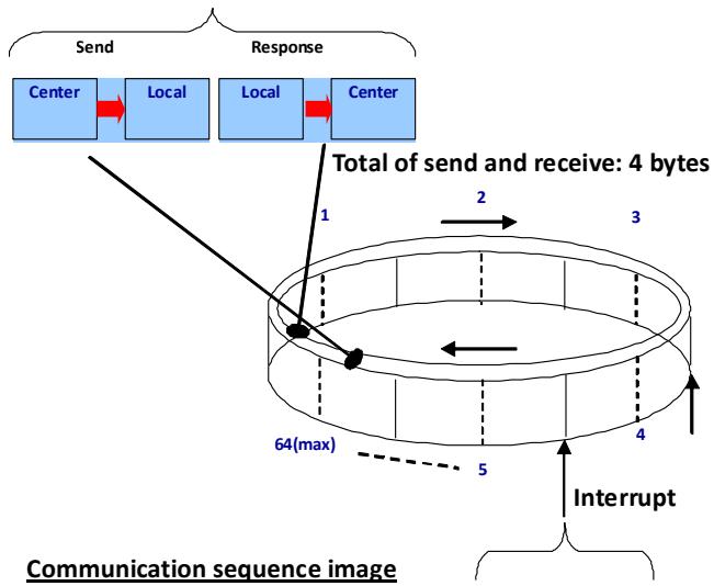
For command delivery procedures which are transferred, in a cyclic communication, the time allowed for communication by a single module is fixed. However, in a data communication, the communication time will vary, depending on how the communication is controlled by the user's program and the time needed to access the PCI-7856. We will skip these elements and simply calculate the basic data communication time in this section.

Cyclic communication
![The image displays a 'Communication sequence image' diagram featuring a top block diagram connected to a 3D ring buffer.\n\n**Top Block Diagram:**\n*   There are two pairs of blue rectangular blocks arranged horizontally.\n*   The first pair is grouped by a bracket labeled '**Send**'. It contains a block '**Center**' connected by a red arrow pointing right to a block '**Local**'.\n*   The second pair is grouped by a bracket labeled '**Response**'. It contains a block '**Local**' connected by a red arrow pointing right to a block '**Center**'.\n\n**Connections to Ring Buffer:**\n*   A black line extends from the first '**Center**' block downwards to a black dot on the left side of the ring buffer.\n*   A black line extends from the second '**Local**' block downwards to a black dot on the right side of the ring buffer. This connection is near a vertical label '**1**'.\n\n**Ring Buffer and Labels:**\n*   The central element is a 3D cylindrical ring buffer.\n*   Text above the ring reads '**Total of send and receive: 4 bytes**'.\n*   Around the rim of the ring, there are numerical labels: '**1**' (near the top left connection), '**2**' (near the top right), '**3**' (far right), and '**4**' (bottom right).\n*   Inside the ring, there is an arrow pointing left. On the top rim, there is an arrow labeled '**2**' pointing right. On the far right side, an arrow points upward.\n*   At the bottom, there is a dashed line labeled '**5**' and text '**64(max)**'.\n*   At the bottom right, there is text '**Interrupt**'.\n*   At the very bottom left, the title '**Communication sequence image**' is underlined.](.pci-7856-50-11163-1000-200/b1867711cbcebf8c7c77b3265927a1be53db4754e5831bc6872ddf6470646e35.jpg)

Data communication
(Send, Receive)

# 3.2 MNET Motion Modules

MNET motion slave module is a wire-saving solution. ADLINK offers three specific types of modules for connecting to Mitsubishi J3 servos, Panasonic A4 servos and Yaskawa Sigma II, III and V servos. Each module is easy and convenient to plug into the servo drivers. All of the servos can be connected serially through the recommended cable, greatly reducing wiring requirements.

<table><tr><td>Series</td><td>Model</td><td>Servo Driver</td><td>Axis No.</td><td>Mechanical I/O</td></tr><tr><td rowspan="3">MNET Single Axis Motion Modules</td><td>MNET- MIA</td><td>Panasonic A4</td><td>1</td><td>PEL, MEL, ORG, SD, EMG</td></tr><tr><td>MNET- J3</td><td>Mitsubishi MR-J3</td><td>1</td><td>PEL, MEL, ORG, SD, EMG</td></tr><tr><td>MNET- S23</td><td>Yaskawa Sigma II, III</td><td>1</td><td>PEL, MEL, ORG, SD, EMG</td></tr><tr><td rowspan="2">MNET 4-axes Motion Modules</td><td>MNET-4XMO</td><td>General Purposed</td><td>4</td><td>PEL, MEL, ORG, SD, EMG</td></tr><tr><td>MNET-4XMO-C</td><td>General Purposed</td><td>4</td><td>PEL, MEL, ORG, SD, EMG, TRG</td></tr></table>

# Table 3-2: MNET Motion Module Series

Not only are specific single axis control modules supported, but also 4-axes control modules namely “MNET-4XMO” and “MNET-4XMO-C”. Both offer the fundamental motion functions such as point-to-point, zero-position searching, programmable acceleration/ deceleration, T/S curve speed profile and so on. Besides the MNET-4XMO-C supports high-speed position comparison, trigger output function and point table for continuous contouring application, please refer to the user guide of MNET-4XMO for more details.

# 3.2.1 Single Axis Motion Modules

ADLINK offers three different types motion module which was used for three specific servos.

1. The MNET-J3 can control a servomotor when I/O signals from a Mitsubishi's MR-J3 series servo driver CN1 are routed directly to this connector, CN4.
2. The MNET-MIA can control a servomotor when I/O signals from a Panasonic's (Matsushita's) servo amplifier MINAS A4 series (pulse command supporting type) servo amplifier CNI/F or CNX5 are routed directly to this connector, CN4.
3. The MNET-M341-S23 controls Yasukawa ΣII, ΣIII and ΣV series servo pack (pulse train supporting types) by docking all command and feedback signals to the CN1 connector of the servo driver.

These modules can control continuous operations of a servomotor with a variety of speed patterns (constant speed, linear acceleration/deceleration, S-curve acceleration/deceleration, as well as a preset positioning operation, and a zero return operation) using serial communications.

Since these modules can be connected directly to the mechanical I/O signals from a servo driver, they do not need the special servo driver cable that is required for a conventional motion control module. Therefore, these modules will save you many hours in designing and wiring your system. The motion module brings many advantages such as simplified wiring, shortened wiring runs, and it eliminates problems caused by faulty wiring. It also offers high noise immunity and takes full advantage of high-speed signal lines to handle command pulses. This module is so compact that it does not need any extra space left for wiring.

If you want to control a servo or stepper motor and it is not described above or you need more advanced motion function like linear / circular interpolation motion (but not PTP motion). ADLINK also provides the 4-axes motion control modules for complicated applications. By using the specific or general purposed D-Sub cables and therefore you can connect the servo drivers directly which include Mitsubishi J2S, Panasonic MINAS A4, Yaskawa Sigma II, III and V series and Delta ASDA A2 series.

![74.9\n69\nCN1\nCN4\nCN3\nCN2\nCN1\nS3\nIO1F1\nIO1F2\nJP7\nJP3\nHS1\nHS2\nJP6\nJP5\nEMG\nJ8\nS1\n1 2 3 4 5 6\nON\nON\nS2\nON\n12\n16 2.3\n16 5.3](.pci-7856-50-11163-1000-200/d16621add161b22c60cc1cb2950d5668f3d87ca72f54d683b829beafc31ec1a5.jpg)

Figure 3-2: MNET-4XMO-(C) Mechanical Diagram

![The image displays technical line drawings of a **Mitsubishi J3 Servo** drive, featuring multiple views with dimensional annotations in millimeters (**Unit: mm**).\n\n*   **Top Section:** On the left is a front view of the drive's ports. To the right is a side profile with a horizontal dimension of **(68.5)**. The text **Mitsubishi J3 Servo** is printed next to the side view.\n*   **Middle Section:** Shows a detailed view of connectors labeled **CN2** and **CN1**. Horizontal dimensions are **52.4** and **44**, and a vertical dimension is **16.3**.\n*   **Bottom Section:** Features a side profile on the left and a rear view with mounting holes on the right. Vertical dimensions include **(3)** at the top, **64.3** for the main body height, and **(2,2)** at the bottom feet. The text **Unit: mm** appears on the far right.](.pci-7856-50-11163-1000-200/1c09a1a82d4db5ecc3bca4dc42d85702a847141d26f620ea4f90475b8db3e47b.jpg)
Figure 3-3: Outline of the MNET-J3 Assembly with MR-J3 Servo Driver

![Panasonic\nM\nS\nD\nS\nKM\nNV\nN\nP\nR\nP\nR\nP\nR\nP\nR\nP\nR\nP\nR\nP\nR\nP\nR\nP\nR\nP\nR\nP\nR\nP\nR\nP\nR\nP\nR\nP\nR\nP\nR\nP\nR\nP\nR\nP\nR\nP\nR\nP\nR\nP\nR\nP\nR\nP\nR\nP\nR\nP\nP\nR\nP\nR\nP\nR\nP\nR\nP\nR\nP\nR\nP\nR\nP\nR\nP\nR\nP\nR\nP\nR\nP\nR\nP\nR\nP\nR\nP\nR\nP\nR\nP\nR\nP\nR\nP\nR\nP\nR\nP\nR\nP\nR\nP\nR](.pci-7856-50-11163-1000-200/9aab1095b84fdbb937b48fa07b07035c1f829fb029a498924421d42ea680d06f.jpg)

![(62.6)\nSPEFIC\nADBEY35\nSEL\nTR\nSM\nSPFIC\nSLP\nQ](.pci-7856-50-11163-1000-200/97ed58c4dccc570c2fa0a1d4287a5bb7a6063753785aff1c783578bbc9a6cd10.jpg)

![52.4\n44\n16.3](.pci-7856-50-11163-1000-200/f1bd698f21a3c1bf8a50caf68c064eb2dad9e3ab667d551892799d1ba210b33c.jpg)

![Pure mechanical assembly diagram without any text, numbers, or symbols](.pci-7856-50-11163-1000-200/ead76d4752d315bbca06e1104953f76721f7a0f74a67db32507d1b9add450575.jpg)

![(3)\n64.3\n(2.2)](.pci-7856-50-11163-1000-200/e8cab7be88460770d4cfa6e474e5467530798fde43510060660be49cfe7171ce.jpg)

Figure 3-4: Outline of MNET-MIA Assembly with a MINAS A4 Servo Driver

![The image is a technical engineering drawing of a YASHAWA SERVOPACK device, displaying four views with dimensional annotations.\n\n**Top Left (Front View):**\n- Top left corner: 'YASHAWA'.\n- Below logo: 'SERVOPACK'.\n- Below that: A blank label box.\n- Terminal block labels (top to bottom): 'CHARGE', 'L1', 'L2', 'L1C', 'L2C', 'B1/', 'B2', 'U', 'V', 'W'.\n- Symbols: A warning triangle next to 'CHARGE'. Ground symbol and positive (+) symbols near the bottom terminals.\n- Connectors: Two D-sub connectors labeled 'CN1' and 'CN2'. Two rectangular connectors at the bottom.\n\n**Top Right (Side View):**\n- Dimension at top: '(62,5)'.\n- Shows mounting holes (hex nuts).\n- Switch area labels: 'SW1', 'ADDR', 'SCL ON'.\n- Side profile with rectangular cutouts.\n\n**Middle (Bottom View):**\n- Horizontal dimensions: '52.4' and inner dimension '44'.\n- Vertical dimension on right: '16.3'.\n- Connectors aligned horizontally with labels 'CN3', 'CN2', 'CN1'.\n\n**Bottom Right (Rear View):**\n- Vertical dimension: '64.3'.\n- Small top dimension: '(3)'.\n- Small bottom dimension: '(2.2)'.\n- Switch area labels: 'SW1', 'ADDR', 'SCL ON'.\n- Four mounting holes (hex nuts) in the corners.\n\n**Bottom Left (Side Profile):**\n- Shows the side profile of the device.](.pci-7856-50-11163-1000-200/000011c9bd30547570a32d96b30e2a160fb2e7c05c1d1a79536c11806b178289.jpg)
Figure 3-5: Outline of MNET-S23 Assembly with a Sigma II, III & V Servo Driver

# 4 HSL Slave Modules

The HSL is a master-slave network system, which features an innovative distributed architecture that modularizes the communication, I/O functions and signal termination. ADLINK provides slave I/O modules and terminal base to meet your particular applications requirement including discrete I/O, analog I/O, and motion control. As for motion control module, please refer to the HSL-4XMO user manuals.

Slave I/O Module: There are three groups of the slave I/O module with individual dimensions. The slave I/O module gives the terminal base different I/O capability. To identify each slave I/O module in a HSL network, a module type electronic data sheet is inherent in the module itself. And the slave I/O module located by address ID, which is selectable by a 6-bit DIP-switch. Depending on different I/O supported, every slave I/O module may consume 1 or 2 address ID. Since the greatest ID number in a HSL master is 63 (6 bit and '0' reserved for master), there are at most 63 slave I/O modules in one HSL master.

Terminal Base: The job of terminal base (TB) is offering an easy wiring media. Both power and signal wiring go from terminal base into the slave I/O modules. Also, the RJ-45 connector used to link the masters to all the slave I/O modules on it. With the help of TB, the slave I/O modules are hot swappable without interfering with other modules in the same HSL network.

U series: In addition to Terminal Base products, ADLINK also offers the slave modules which were named U-series. U-series slave modules offer I/O signal wiring on module top directly. It is more compact size than Terminal Base slave modules, moreover, it offers several kinds of I/O interface to perform signal linking.

HUB/Repeater: HSL-HUB/Repeater provides customers sub-system idea for different topology use.

Wiring Cable: The communication wiring cables among the HSL master and I/O modules are standard 100 Base/TX with RJ-45 connectors. There are exactly the same as commercial Ethernet cables.

# 4.1 HSL Slave I/O Module

# 4.1.1 Discrete I/O Module

ADLINK provides three series: DB, M and U series.

▶ DB: Daughter board form factor
▶ M: Daughter board form factor with aluminum cover
▶ U: Low-profile design

These series are listed as follows:

<table><tr><td>Series</td><td>Model</td><td>Discrete Input</td><td>Discrete Output</td><td>Relay Output</td><td>Slave Index Occupation</td></tr><tr><td rowspan="3">DB</td><td>DBHSL-DI32-DB-N/P</td><td>32</td><td></td><td></td><td>2 (Consecutive from odd number)</td></tr><tr><td>HSL-DO32-DB-N/P</td><td></td><td>32</td><td></td><td>2 (Consecutive from odd number)</td></tr><tr><td>HSL-DI16DO16-DB-N/P</td><td>16</td><td>16</td><td></td><td>1</td></tr><tr><td rowspan="4">M</td><td>HSL-DI32-M-N/P</td><td>32</td><td></td><td></td><td>2 (Consecutive from odd number)</td></tr><tr><td>HSL-DO32-M-N/P</td><td></td><td>32</td><td></td><td>2 (Consecutive from odd number)</td></tr><tr><td>HSL-DI16DO16-M-NN/NP/PN//PP</td><td>16</td><td>16</td><td></td><td>1</td></tr><tr><td>HSL-R8DI16-M-N/P</td><td>16</td><td></td><td>8</td><td>1</td></tr><tr><td rowspan="2">U</td><td>HSL-DI16DO16-US/UJ-NN/NP/PN/PP</td><td>16</td><td>16</td><td></td><td>1</td></tr><tr><td>HSL-DI16-UL</td><td>16</td><td></td><td></td><td>1</td></tr></table>

Table 4-1: HSL Discrete I/O Module Series

The selection guide is as follows:

![HSL - DI□DO□ - □ - XY](.pci-7856-50-11163-1000-200/cfce885cfe942317212303ba643ba39ed48ad3de8e8083266b648af8fc1185db.jpg)

# Discrete I/O Type:

▶ DI16DO16: 16 discrete inputs and 16 discrete outputs
▶ DI32: 32 discrete inputs
▶ DO32: 32 discrete outputs
▶ R8DI16: 8 relay outputs and 16 discrete inputs

# Series:

▶ DB: Daughter board form factor
▶ M: Daughter board with aluminum cover
▶ U: U Series
▶ DB: Daughter board form factor

# Signal Type:

▶ X: Input Signal Type: NPN sinking and PNP sourcing support
▶ Y: Output Signal Type: NPN sinking and PNP sourcing support

Table 4-2: HSL Discrete I/O Module Selection Guide

# 4.1.2 Analog I/O Module

ADLINK provides an M series as follows.

<table><tr><td>Series</td><td>Model</td><td>Analog Input</td><td>Analog Output</td><td>Slave Index Occupation</td></tr><tr><td>M</td><td>HSL-AI16AO2-M-VV</td><td>16</td><td>2</td><td>2 (Leap number)</td></tr><tr><td></td><td>HSL-AI16AO2-M-AV</td><td>16</td><td>2</td><td>2 (Leap number)</td></tr><tr><td>U</td><td>HSL-AO4</td><td></td><td>4</td><td>2</td></tr></table>

Table 4-3: HSL Analog I/O Module Series

The selection guide is as follows.

![The image displays a product selection guide or part numbering system flowchart.\n\n**Top Row Blocks (connected by hyphens):**\n*   **HSL**\n*   **AI□AO□** (where □ represents a checkbox/square)\n*   **□** (a single checkbox/square)\n*   **XY**\n\n**Detailed Columns below the blocks:**\n\n**Column 1 (under AI□AO□):**\n*   **Discrete I/O Type:**\n*   ► AI16AO16: 16 analog inputs and 2 analog out- puts\n\n**Column 2 (under □):**\n*   **Series:**\n*   ► M: Daugther board with aluminum cover\n\n**Column 3 (under XY):**\n*   **Signal Type:**\n*   ► X: Input signal type, V means voltage and A means current.\n*   ► Y: Output signal type, V means volt- age.](.pci-7856-50-11163-1000-200/8fbac441dd088e5837aac3c6ed048698de897c592e266a94fd55031540914b4d.jpg)

Table 4-4: HSL Analog I/O Module Selection Guide

# 4.2 General Specifications

# 4.2.1 Digital I/O Module

<table><tr><td rowspan="8">Discrete Input</td><td>Photo couple isolation</td><td colspan="2">2500 VRMS</td></tr><tr><td>Input impedance</td><td colspan="2">4.7 kΩ</td></tr><tr><td>Input Voltage</td><td colspan="2">+24 V*</td></tr><tr><td rowspan="2">Input Current</td><td>For NPN(1)</td><td>-10 mA</td></tr><tr><td>For PNP(2)</td><td>+10 mA</td></tr><tr><td rowspan="2">Operation Voltage (@ 24 VDC Power Supply)</td><td>For NPN(1)</td><td>ON: 11.4 VDC(Max.)OFF: 14.3 VDC (Min.)</td></tr><tr><td>For PNP(2)</td><td>ON: 12.6 VDC(Min.)OFF: 9.8 VDC (Max.)</td></tr><tr><td>Response Time</td><td colspan="2">ON: 8.8 μs (Typical)OFF: 42 μs (Typical)</td></tr><tr><td rowspan="4">Discrete Output</td><td rowspan="2">Switch capacity</td><td>For NPN(3)</td><td>All channels: -50 mA/ch at 24 VDC</td></tr><tr><td>For PNP(4)</td><td>All channels: +50 mA/ch at 24 VDC</td></tr><tr><td rowspan="2">Response Time</td><td colspan="2">ON to OFF: 68 μs</td></tr><tr><td colspan="2">OFF to ON: 1.1 μs</td></tr><tr><td rowspan="5">Relay</td><td>Relay Type</td><td colspan="2">SPST, normally open, non-latching</td></tr><tr><td>Rating</td><td colspan="2">30 VDC/2 A, 250 VAC/2 A</td></tr><tr><td>Switching Frequency</td><td colspan="2">20 times/minute at rating load</td></tr><tr><td rowspan="2">Response Time</td><td colspan="2">ON to OFF: 3 μs (Max.)</td></tr><tr><td colspan="2">OFF to ON: 6 μs (Max.)</td></tr></table>

Table 4-5: Digital I/O Module

(1): NPN sinking type sensor input module
(2): PNP sourcing type sensor input modules
(3): NPN sinking type sensor output module
(4): PNP sourcing type sensor output modules
(5): U-series single channels: -90 mA at 24 V $_{DC}$

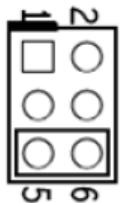
\*Note: The HSL-DI16-UL supports 5 V, 12 V and 24 V, selected by jumper for each channel:

▶ JDI0 - JDI15 (input voltage setting)
![1\n2\n5 6](.pci-7856-50-11163-1000-200/5fbd4e6d5c9a664b72340ee7dd69c3006522fa5bbf0d6dbf292d812b3a445e71.jpg)

5 V

12 V

24 V (default)

# 4.2.2 Analog I/O Module

<table><tr><td rowspan="5">Analog Input</td><td>A/D Resolution</td><td>16-bit (14-bit guaranteed)</td></tr><tr><td rowspan="2">Input Range</td><td>For VV type: ±10 V, ±5, ±2.5, ±1.25 V</td></tr><tr><td>For AV type: 20 mA, 10 mA, 5 mA</td></tr><tr><td>A/D Conversion</td><td>10 μs</td></tr><tr><td>Signal Type</td><td>16-CH Single Ended; 8-CH Differential</td></tr><tr><td rowspan="2">Analog Output</td><td>D/A Resolution</td><td>16-bit</td></tr><tr><td>DA Settling Time</td><td>10 μs</td></tr></table>

Table 4-6: Analog I/O Module

# 4.2.3 DIP Switch Setting

![ON\n1 2 3 4 5 6](.pci-7856-50-11163-1000-200/def35686809b11f8e8b584e19a8285e294e9869fe0abe8e5011abe2732befcd3.jpg)

ON = 1

100000 address 1

010000 address 2

... ...

011111 address 62

111111 address 63

OFF = 0

# Please note the following:

1. The address (or slave index) '0' is reserved.
2. HSL-DI32-M, HSL-DO32-M, HSL-DI32-DB, and HSL-DO32-DB need two consecutive addresses that start from an odd number. For example, if the DIP switch is set as 3, it would occupy slave index 3 and 4.
3. HSL-AI16AO2-M-VV/AV needs two leap addresses at full duplex mode. For example, if the DIP switch is 2, this module will occupy 2 and 4.

# 4.2.4 Wiring Diagram

-N NPN Sinking type sensor Input

![Circuit\nv+\nIN\nG\n4.7kΩ\nLED\nInternal Circuits](.pci-7856-50-11163-1000-200/0e88bc60c43120f7e57b0480e55859b58ee65be310806d22148a2793a1509475.jpg)

-N Dry Contact Input

![v+\nIN\nG\n4.7kΩ\nLED\nInternal Circuits](.pci-7856-50-11163-1000-200/f86a54f4c9d4f675c7ecb24d5facfcf1f9590d4fedc13ef54ab57e84d4b15e90.jpg)

-P PNP Sourcing type sensor Input
![Circuit\nV+\nIN\nG\n4.7kΩ\nLED\nInternal Circuits](.pci-7856-50-11163-1000-200/4fed54895563cbe8ec074340b76ef33f422a4d22385fec7d652220642c6f06db.jpg)

-P Wet Contact Input
![v+\nIN\n4.7kΩ\nG\nLED\nInternal\nCircuits](.pci-7856-50-11163-1000-200/c315973ced8504468e10093d52dc535c73c4368c42f7983d632d4b51889424ac.jpg)

-N NPN Sinking Output
![LED\nInternal\nCircuits\nV+\nLoad\nOut\nG](.pci-7856-50-11163-1000-200/a46ac525e07eeb4e856e9b268e7f657172b695c74cef84a612baa47485fb2acb.jpg)

-P PNP Sourcing Output
![LED\nInternal\nCircuits\nV+\nOut\nLoad\nG](.pci-7856-50-11163-1000-200/77b9d8049c63f57569d145199a2814bfb6f3202fe98b38ec0e3a985214eb2a7a.jpg)

-R Relay Output
![The diagram displays a block diagram for a Solid State Relay (SSR) system.\n\n**Labeled Blocks:**\n*   **LED**: Depicted as a diode symbol with arrows pointing outward.\n*   **Internal Circuit**: A rectangular block.\n*   **SSR**: A rectangular block.\n*   **NO.n**: A terminal label.\n*   **COM.n**: A terminal label.\n*   **Load**: A resistor symbol.\n\n**Connections:**\n*   The **LED** is connected across the top portion of the **Internal Circuit** block.\n*   The **Internal Circuit** block is connected to the **SSR** block.\n*   The **SSR** block outputs two lines labeled **NO.n** and **COM.n**.\n*   The **NO.n** line connects to the left side of the **Load** resistor.\n*   The right side of the **Load** resistor connects to a battery symbol.\n*   The negative terminal of the battery symbol connects to the line labeled **COM.n**.\n*   An AC source symbol (circle with a tilde) is connected via a dotted line to the **COM.n** line.](.pci-7856-50-11163-1000-200/7090e355904ba20980793e1b3d20b24e5fabb85b283f2c2c2013d9560544da44.jpg)

-Analog Input (Differential Voltage Input)
![Based on the provided image, here is the accurate description of the flowchart/block diagram:\n\n**Labeled Blocks and Elements:**\n*   **Text:** 'Differential Signal Source' (top left)\n*   **Symbol:** AC Voltage Source (circle with a sine wave)\n*   **Symbol:** DC Voltage Source (battery symbol)\n*   **Text:** '(30V' (next to the DC source)\n*   **Symbol:** Ground (triangle pointing down)\n*   **Text:** 'AGND' (below the ground symbol)\n*   **Text:** 'IN(+)' (inside the dashed box)\n*   **Text:** 'IN(-)' (inside the dashed box)\n*   **Text:** 'ADC' (inside the rectangular block)\n*   **Visual Element:** A dashed rectangular box enclosing the input terminals and the ADC block.\n\n**Connections:**\n*   The top wire from the AC Voltage Source connects to the **IN(+)** terminal.\n*   The bottom wire from the AC Voltage Source connects to the **IN(-)** terminal.\n*   The bottom wire from the AC Voltage Source also connects to the positive terminal of the DC Voltage Source.\n*   The negative terminal of the DC Voltage Source connects to the **AGND** ground symbol.\n*   Arrows connect the **IN(+)** terminal and the **IN(-)** terminal to the **ADC** block.](.pci-7856-50-11163-1000-200/622e17a460ab00428879c32d74cc07e8d7474de5ff62bf674336c72825fbad27.jpg)

-Analog Input (Single-End Voltage Input)
![Based on the provided diagram, here is the description:\n\n**Labels:**\n*   'Ground Signal Source'\n*   'IN(+)'\n*   'AGND'\n*   'ADC'\n\n**Connections:**\n*   An AC source symbol (circle with a sine wave) is connected to a ground symbol (triangle pointing down).\n*   The top terminal of the source connects via an arrow to the input labeled **IN(+)**.\n*   The bottom terminal of the source connects via an arrow to the input labeled **AGND**.\n*   Both **IN(+)** and **AGND** are enclosed within a dotted rectangular box.\n*   Arrows extend from **IN(+)** and **AGND** into a rounded rectangular block labeled **ADC**.](.pci-7856-50-11163-1000-200/0da8cd51d32679168c589220ea0d923fc3945a25e2f92c61e54f39fe526dfb00.jpg)

# -Analog Input (Current Measure)

![This diagram depicts an analog-to-digital conversion setup. On the left, a **Current Source** (symbolized by a circle with an upward arrow) is connected in parallel with a resistor labeled **R**. Text below the resistor specifies **R=125 Ohm** and **%1 accuracy**.\n\nTwo arrows connect this parallel combination to an input stage inside a dashed boundary. The top input terminal is labeled **IN(+)** and the bottom terminal is labeled **IN(-)**. Finally, two arrows connect these input terminals to a large block on the right labeled **ADC**.](.pci-7856-50-11163-1000-200/04d175e1b791782805f37458e28a9a28ad9cd2b53008afdceb2a4a00f95124ee.jpg)

# Dimensions

\- DB: Daughter board form factor (100 mm X 78.2 mm)

![100\n94\nØ3.2 49L\n75\n78.2\n2.26\n4.2\n2.5\n46.43\n28\n9\n4\n82\n97](.pci-7856-50-11163-1000-200/dec73fe7c3642ec15f0c1497f5698cd0eb1d2ca11f941437c3a8d5b091a2ac2a.jpg)

\- M: Daughter board with aluminum cover (125 mm X 80 mm)

![125\n22.4\n108\n80\n116\n0.7\n13.4](.pci-7856-50-11163-1000-200/34b5b100e23584f92b0ff3ca0b4df7c06eedbb9caad57db6a8941a02c79b2926.jpg)

- U-series slave I/O module (71.8 mm X 138 mm)
![This image is a technical engineering drawing showing two orthographic views of an electronic device.\n\n**Top View:**\nThe upper section depicts the top surface of the device.\n*   **Dimensions:** Vertical measurements on the left are labeled '71.8' and '69'. Horizontal measurements at the bottom are labeled '135' and '138'.\n*   **Components:** Along the top and bottom edges are long rectangular connectors with multiple pin rows. In the center is a dense grid of text labels arranged in two rows, containing identifiers such as 'L100', 'L101', 'L102', 'L103', 'L104', 'L105', 'L106' on the top row and 'L107', 'L108', 'L109', 'L110', 'L111', 'L112', 'L113' on the bottom row. To the right, there are smaller connector blocks and a large rectangular outline with small squares inside. Near the bottom right, there are square components with circular details.\n\n**Bottom View:**\nThe lower section depicts the bottom surface of the device.\n*   **Dimensions:** A vertical measurement on the left is labeled '52.7'.\n*   **Components:** On the left and right edges are vertical mounting brackets. In the center is a large shape with two upward protrusions. To the right are two rectangular outlines resembling ports (possibly USB or Ethernet). Along the bottom edge, there are four circular holes, likely for mounting screws.](.pci-7856-50-11163-1000-200/60f671bad3296fb92b943c0ff4aae57d3b76599764c3bb47182991a1239868c7.jpg)

# 4.2.5 Terminal Base Motion Control Module

The terminal bases include:

▶ HSL-TB32-U-DIN
▶ HSL-TB64-DIN
▶ HSL-TB32-M-DIN
▶ HSL-TB32-MD

# Features

▶ Field I/O wiring connection for HSL I/O modules
▶ Screw or spring terminal for easy field wiring
▶ Power and ground included for each signal channel
▶ Interlocking design for rugged installation
▶ Power LED indicator
▶ DIN rail mounting
▶ Onboard Terminator resistor

# General Description

<table><tr><td></td><td>Model Name</td><td>Description</td><td>Module Support</td></tr><tr><td rowspan="2">DB Series</td><td>HSL-TB32-U</td><td>(1) 32 channels direct connected terminal base(2) One DB slot</td><td>All HSL DB-series modules</td></tr><tr><td>HSL-TB64</td><td>(1) 64 channels direct connected terminal base(2) Two DB slots</td><td>All HSL DB-series modules</td></tr><tr><td rowspan="2">M Series</td><td>HSL-TB32-M</td><td rowspan="2">32 channels direct connected terminal base for HSL M-series module</td><td rowspan="2">All HSL M-series modules</td></tr><tr><td>HSL-TB32-MD</td></tr></table>

# Jumper Settings

Since HSL is a serial transmission system, a terminator should be placed at the end of cable. Each TB has a jumper selectable terminator on board. Only the last module have to enable the terminator.

Not the last module (Default)
![5 3 1\nOFF ON\n6 4 2](.pci-7856-50-11163-1000-200/926125e3aa97fe0ebb9ea5f56809266955823f1a9fc9039729f992e1eb542836.jpg)

The last module
![5 3 1\nOFF ON\n6 4 2](.pci-7856-50-11163-1000-200/a32bc77a25a8bc2bff97e786cfb34f333349bcd2ee7b012557a35ea3d1508e61.jpg)

# HSL-TB32-MD Jumper Setting

JP1,2 (External Power Option)
![1 2 3\n1 2 3](.pci-7856-50-11163-1000-200/d9228626292f0709b50f1fe1f35d6d9b2639d944b2d726e330ba866f7f9af722.jpg)

1, 2 short: Different Power (Default)
2, 3 short: Common Power

JP3 (Tx Terminal Resistor)
![ON\n3\n2\n1\nOFF](.pci-7856-50-11163-1000-200/74726695504321df9d3636710bdf860508cca03902db386601e4e57389c8db05.jpg)

OFF is default setting

JP4 (Rx Terminal Resistor)
![ON\n3\n2\n1\nOFF](.pci-7856-50-11163-1000-200/03ca880eeeaf1e308120b785fdf712ed3fbf51fc011bcb346a0c5c746afbe76d.jpg)

OFF is default setting

JP5 (Fuse Option)
![1 2 3\nON OFF](.pci-7856-50-11163-1000-200/c723d23786141601bea0db0fab7adc9e29262333bb39b618712693c575ac420d.jpg)

1, 2 short: With Fuse
2, 3 short: Without Fuse (Default)

# Dimensions

-DB with HSL-TB32-U-DIN (126x120.1x107.3) mm

![10K\n10K](.pci-7856-50-11163-1000-200/31d6d5e816d43117c07c97dd487389e875d2d6063b62f06dbc25cc22509b420a.jpg)

![Pure mechanical diagram showing a spring-loaded frame with no text or symbols](.pci-7856-50-11163-1000-200/82687526ced8ebe0c75ff56ac6e78247967bc7d1feb10944ebce936d4040eb65.jpg)

![R7.5\n40.4](.pci-7856-50-11163-1000-200/11a277bf7ac0b5449563375233865e9312555a0d9999d79dcb388efdca5aac36.jpg)

![168.7\n128.7](.pci-7856-50-11163-1000-200/250018a4580e273e33bfaeea7b6b4b712014c91df9cfa7f7fe7ced87cb869a1d.jpg)

![Technical line drawing of a mechanical assembly with spring-loaded components and a 1024mm dimension label (no text or symbols beyond measurement)](.pci-7856-50-11163-1000-200/8ffe58d8404edfb1f48da0d91096d93c87b2edc5a6832ba0db12919ead6dfbc1.jpg)

![8.0 x 1.7\n6.5](.pci-7856-50-11163-1000-200/bfd055bc3c805ccbb2d34dabee08264b8ececc7785992f038d891cb81d1dd243.jpg)

-DB with HSL-TB64-DIN (168.7x120.1x107.3) mm

![168.7\n128.7](.pci-7856-50-11163-1000-200/ec9880702767ed1b915e6c04383affec7267ed814d8af804e6973b11bce8316c.jpg)

![Technical line drawing of a mechanical assembly with spring and base plate (no text or symbols)](.pci-7856-50-11163-1000-200/68c3fb201ee3e3ffd94566531a7f8398181dc3f3bd252bec5b6b3084efb4d126.jpg)

![8.5\n6.7](.pci-7856-50-11163-1000-200/5ce01db8e0e3dfe4827736c301de3bee8fbfd4a7fe7259d4e193dff09c476d48.jpg)

-M module with HSL-TB32-M-DIN (128.5x85.5x108) mm

![128.9\n80.4](.pci-7856-50-11163-1000-200/6bde13ba2438b54abec51846bc17ed6cf67a61a2d0fcef87f6132d0691d82eb5.jpg)

![Pure technical line drawing of a mechanical assembly without any text, numbers, or symbols](.pci-7856-50-11163-1000-200/736c54652afb102d0f709a8bb0fee7e6402c70b900b1bb65de70229864bb8937.jpg)

![Technical line drawing of a mechanical component with dimension annotations (no readable text or symbols)](.pci-7856-50-11163-1000-200/fce499e9752eabc00112ecdcb1a4c459a1b175b09755a0f45bee094113b0095f.jpg)

-HSL-TB32-MD (129x107) mm
![167\n129](.pci-7856-50-11163-1000-200/4972d277c06153d862f336143a70b8567d239259c3bea1be492e412222c32382.jpg)

# 4.2.6 HSL-HUB/Repeater

HSL-HUB/Repeater including:

▶ HSL-HUB
▶ HSL-Repeater

# Feature

- Linking style: Master to HUB, HUB to HUB, HUB to Slave
▶ Support T bracing connection / Star connection (Subsystem Concept)
▶ Support Max. 2.4km by 7 HSL-HUB/Repeater modules
▶ One input port with 3 output segment ports
▶ Jumper selectable transmission speed : 3/6/12 Mbps
▶ Full and half duplex transmission mode are jumper selectable
▶ RJ45 phone jack for easy installation
▶ 24 VDC input

General Description
![The diagram presents a comparison of two configurations, arranged vertically.\n\n**Top Section:**\n*   **Label:** 'Without HSL-HUB'\n*   **Blocks:** 'Master Controller' (pointing to a white box) and 'Add One More' (an orange box pointing to a gap between modules).\n*   **Labels:** 'A' and 'B' (associated with purple dashed arrows).\n*   **Connections:** Blue pipes connect a grid of white rectangular modules. Purple dashed arrows labeled 'A' and 'B' point towards the interface between the modules.\n\n**Bottom Section:**\n*   **Label:** 'With HSL-HUB'\n*   **Blocks:** 'Master Controller' (pointing to a white box) and 'Add One More' (an orange box pointing to a gap between modules).\n*   **Graphic:** A blue starburst shape containing the text 'Excellent'.\n*   **Connections:** Copper-colored pipes connect a grid of white rectangular modules. A red dashed line connects the text 'With HSL-HUB' to the 'Excellent' starburst.](.pci-7856-50-11163-1000-200/4a7bcec01ccb11fc5336f5f0837ec0e86d1059f02a61d87ced2335b83c26e315.jpg)

Figure 4-1: HSL System Configuration

# Jumper Settings

FD / HD setting: JP\*(0-3), JFH1

Full Duplex (default)
![FA HD\nJP\nFD HD\nJFH1](.pci-7856-50-11163-1000-200/fa3c9eb895690ba9f85497d8f7dc8d71a6de615ffe7199c906e720037701ecac.jpg)

Half Duplex
![FD HD\nJP\nJFH1 FD HD](.pci-7856-50-11163-1000-200/c1106a2631b93cf05d3fe7ec62910b9ebb6c098e9ed6c1cdeab0ae6f7c1b6129.jpg)

3 M / 6 M / 12 M setting JBPS1

![Abstract geometric pattern with black squares and white outlines (no text or symbols)](.pci-7856-50-11163-1000-200/8406640a4119aac0b2f4222659ca7b32003c932c22851c0de364a0aba6d8a5ae.jpg)

6 M (default)

<table><tr><td>1 – 3 &amp; 2 – 4</td><td>12 M</td></tr><tr><td>1 – 3 &amp; 4 – 6</td><td>6 M (default)</td></tr><tr><td>3 – 5 &amp; 2 – 4</td><td>3 M</td></tr><tr><td>3 – 5 &amp; 4 – 6</td><td>EXC</td></tr></table>

# Dimensions

HSL-HUB
![72\n80](.pci-7856-50-11163-1000-200/a72c5af81d8c2a50e8b09353be04d130517e25765195c980abb60e2d156d2f5e.jpg)

HSL-Repeaters
![72\n48](.pci-7856-50-11163-1000-200/8760151d97db4491bc388cef2b1a5664ed3d1adcf5ae6145e72e1870f388cf54.jpg)

# 4.2.7 Managing Slave Index in an HSL Network

# Before you proceed

Before powering on the slave modules, users have to adjust the DIP switch. For this step, please refer to Section 4.2.3 to know how to do this. Please specifically note the following.

1. One master controller can connect up to 63 slave indexes.
2. The more compact slave address in HSL network, the much more efficient the HSL system can work.
3. Discrete I/O and relay module rule

<table><tr><td>Module</td><td>Slave Index Occupation</td><td>Transmission Mode</td><td>Transmission Speed</td></tr><tr><td>HSL-DI16DO16-M-NN/NP/PN/PP</td><td rowspan="3">1 (Any address)</td><td rowspan="7">Full Duplex (Fixed)</td><td rowspan="7">6 Mbps (Fixed)</td></tr><tr><td>HSL-DI16DO16-DB-NN/NP/PN/PP</td></tr><tr><td>HSL-R8DI16-M-N/P</td></tr><tr><td>HSL-DI32-M-N/P</td><td rowspan="4">2 (Consecutive from odd number)</td></tr><tr><td>HSL-DI32-DB-N/P</td></tr><tr><td>HSL-DO32-M-N/P</td></tr><tr><td>HSL-DO32-DB-N/P</td></tr></table>

4. Observe the analog I/O and thermocouple module rule.

<table><tr><td>Module</td><td>Slave Index Occupation</td><td>Transmission Mode</td><td>Transmission Speed</td></tr><tr><td>HSL-AI16AO2-M-VV</td><td rowspan="3">2 (Leap number)</td><td rowspan="3">Full Duplex (Fixed)</td><td rowspan="3">3/6/12 Mbps Selectable</td></tr><tr><td>HSL-AI16AO2-M-AV</td></tr><tr><td>HSL-AO4-U</td></tr></table>

5. Special Rule: If you will install only one HSL-AI16AO2-M-VV or HSLAI16AO2-M-AV and the DIP switch is set to 1 (HSL-AI16AO2-M-VV/AV only supports full duplex mode), the occupied indexes will be 1 and 3. You must assign the parameter "MOD\_No" of APS\_set\_field\_bus\_slave\_param() as 4 to ensure correct communication.

# Examples

The following examples are provided for user reference. All modules used are set in full duplex mode.

# Example 1

Provided you installed two HSL-DI16DO16-UD, two HSL-DI32-MN, and an HSL-AI16AO2-VV with all slave modules in full duplex mode, you can have two conditions as follows:

Condition 1 HSL-AI16AO2-VV×1 is in 6 Mbps.

ADLINK suggests users can have the slave index configuration as follows.

<table><tr><td>Item</td><td>DIP Switch</td><td>Index Occupation in HSL</td></tr><tr><td>HSL-DI32-M-N #1</td><td>1</td><td>1, 2</td></tr><tr><td>HSL-DI32-M-N #2</td><td>3</td><td>3, 4</td></tr><tr><td>HSL-AI16AO2-VV</td><td>5</td><td>5, 7</td></tr><tr><td>HSL-DI16DO16-UD #1</td><td>6</td><td>6</td></tr><tr><td>HSL-DI16DO16-UD #2</td><td>8</td><td>8</td></tr></table>

This is an example of a compact composition. The scan time needs 30.33 $\mu$ s x 8 at 6 Mbps, full duplex mode. Users can connect the modules with one master controller.

Condition 2 HSL-AI16AO2-VV×1 operates at 12 Mbps.

We recommended that you use the provided slave index configuration.

<table><tr><td>Item</td><td>DIP Switch</td><td>Index Occupation in HSL</td></tr><tr><td>HSL-DI32-M-N #1</td><td>1</td><td>1, 2</td></tr><tr><td>HSL-DI32-M-N #2</td><td>3</td><td>3, 4</td></tr><tr><td>HSL-DI16DO16-UD #1</td><td>5</td><td>5</td></tr><tr><td>HSL-DI16DO16-UD #2</td><td>6</td><td>6</td></tr></table>

There is another example of a compact composition. The scan time needs 30.33 $\mu$ s x 6 at 6 Mbps, full duplex mode. You may connect these modules with one master controller. The HSL-AI16AO2-M-VV module connects to another master controller. The DIP switch of HSL-AI6AO2-M-VV is assigned as 1.

HSL-D16DO2-UL ×2, HSL-DI32-UD × 2

HSL-AI16AO2-M-VV

6 Mbps
![Four red double-headed arrows are stacked vertically.](.pci-7856-50-11163-1000-200/908e14e443d3a6ba55d48c1491a0c2dac2dc1c9c1080661edbd0454cab5826a9.jpg)
12 Mbps

![This image displays a vertical green printed circuit board, likely a PCIe card, featuring gold contact pins along the bottom edge. On the left side, two network ports are visible. In the center, there are two large black square chips surrounded by smaller components. Three white labels are clearly visible on the board with the text: 'SUN', 'P/N 483-0880 A', and 'QDR 10G Ethernet Adapter'.](.pci-7856-50-11163-1000-200/53fdfc7ef507a59282e0bed07c141aec25d8ef654b081ee30a7b7adcb64c2672.jpg)

Consequently, the cycle time of the first master controller is 30.33 $\mu$ s x 6 and the cycle time of the second master controller is 45.5 $\mu$ s at 12 Mbps, full duplex mode.

# Example 2

Provided you installed two HSL-DI16DO16-UJ, one HSLDI16DO16-M-NN, two HSL-DO32-M-N and one HSL-AI16AO2-VV with all slave modules in full duplex mode, you can have the following conditions:

Condition 1 The HSL-AI16AO2-VV module operates in 6 Mbps.

We recommended that you use the provided slave index configuration.

<table><tr><td>Item</td><td>DIP Switch</td><td>Index Occupation in HSL</td></tr><tr><td>HSL-DO32-M-N #1</td><td>1</td><td>1, 2</td></tr><tr><td>HSL-DO32-M-N #2</td><td>3</td><td>3, 4</td></tr><tr><td>HSL-AI16AO2M-VV</td><td>5</td><td>5, 6</td></tr><tr><td>HSL-DI16DO16-UJ #1</td><td>7</td><td>7</td></tr><tr><td>HSL-DI16DO16-UJ #2</td><td>8</td><td>8</td></tr><tr><td>HSL-DI16DO16-M-NN</td><td>9</td><td>9</td></tr></table>

The scan time needs 30.33 $\mu$ x 17 at 6 Mbps, full duplex mode.

You can connect these modules with one master controller.

Condition 2 An HSL-AI16AO2-VV module operates at 12 Mbps.

We recommended that you use the provided slave index configuration.

<table><tr><td>Group 1</td><td>DIP Switch</td><td>Index Occupation in HSL</td></tr><tr><td>HSL-DO32-M-N #1</td><td>1</td><td>1, 2</td></tr><tr><td>HSL-DO32-M-N #2</td><td>3</td><td>3, 4</td></tr><tr><td>HSL-DI16-UJ #1</td><td>5</td><td>5</td></tr><tr><td>HSL-DI16-UJ #2</td><td>6</td><td>6</td></tr><tr><td>HSL-DI16DO16-M-NN</td><td>7</td><td>7</td></tr></table>

The scan time needs 30.33 $\mu$ s x 7. You may connect these modules with one master controller. The HSL-AI16AO2-M-VV module connects to another master controller. The management table below is for reference.

<table><tr><td>Group 2</td><td>DIP Switch</td><td>Index Occupation in HSL</td></tr><tr><td>HSL-AI16AO2-M-VV</td><td>1</td><td>1, 2</td></tr></table>

Refer to the illustration below.

<table><tr><td>Group 1</td></tr><tr><td>Group 2</td></tr></table>

![The image displays the text '6 Mbps' at the top. Below it are two red double-headed arrows pointing in opposite directions, stacked vertically.](.pci-7856-50-11163-1000-200/20f260f447bed07b1b20fbf898aad641a13191b6c69273fce0772a9b0ccd0ace.jpg)

![The image displays a green circuit board populated with various electronic components, including integrated circuits and connectors. Visible text includes:\n- 'Adaptec' (logo)\n- 'RAID' (in red)\n- 'Adapter' (in blue)\n- 'ADAPTEC' (on a white label at the top right)\n- '500' (on two vertical labels on the left edge)](.pci-7856-50-11163-1000-200/ef192e208d56f35696d71e8ad508425ee57f3009dadc439ac697316ba3812020.jpg)
12 Mbps

The cycle time of the first master controller is 30.33 $\mu$ s x 7, while the cycle time of second master controller is 15.17 $\mu$ s x 11 at 12 Mbps, full duplex mode.

# 5 MotionCreatorPro 2

After installing the hardware, it is necessary to correctly configure all cards and double check the system before running. This chapter gives guidelines for establishing a control system and manually testing the PCI-7856 to verify correct operation. The software provides a simple yet powerful means to setup, configure, test, and debug a motion control system that uses PCI-7856.

Note that MCP2 is only available for Windows 2000, XP and Vista with a screen resolution higher than 1024x768. Recommended screen resolution is 1024x768. It cannot be executed under the DOS environment.

# 5.1 Execute MotionCreatorPro 2

After installing the software drivers for the PCI-7856 in Windows, the MCP2 program can be located at &lt;chosen path&gt;\MCP2.exe. Double click this file to run the program.

# 5.2 About MotionCreatorPro 2

Before running MotionCreatorPro2, the following should noted.

1. MotionCreatorPro2 is a program written by BCB 6.0, and is available only for Windows with a screen resolution higher than 1024x768. It cannot be run under DOS.
2. There are a couple files necessary for this program.

▷ MCP2.mdb records parameters and graphics

▶ MCPro2.ini records initial setting

3. MCP2 is a high integration program that is supports many ADLINK motion control cards. Multiple cards can be used in one system.

# 5.3 MotionCreatorPro 2 Form Introducing

# 5.3.1 Main Window

The main menu appears after running MotionCreatorPro 2. Refer to the following illustrations for a description of the available functions: File\Exit: Close and then exit this program.

![ADLINK\nPC3-7856\nCard No 8\nHSL BusNo 8\n(0D1) HSL-D032\n(0D15) HSL-D16D016\n(0D32) HSL-D16R008\nMNET BusNo1\n(0D8) MNET-0XMO\n● AxisNo - 1588 ServoOff\n● AxisNo - 1581 ServoOff\n● AxisNo - 1582 ServoOff\n● AxisNo - 1583 ServoOff\n(0D1) MNET-0XMO-C\n● AxisNo - 1584 ServoOff\n● AxisNo - 1585 ServoOff\n● AxisNo - 1586 ServoOff\n● AxisNo - 1587 ServoOff\nADLINK\nTECHNOLOGY INC.\nBoard ID: 0\nAPS Library: 90710\nDriver: 906231\nCPLD: 3\nCarrier Board: 0\nB\nC](.pci-7856-50-11163-1000-200/96b24ac741a7f05c6305dfd5f442fdbb5c490afbd88d0596154aa74bd0bbf65e.jpg)

A. Icons for operation modes. Some will be active when a filed bus / motion item in the tree view was selected and some will be active when an axis item is selected.

▶ Functions Button: Use these buttons to select function you want test.

▷ Configuration

<table><tr><td>Button</td><td>Function</td><td>Description</td></tr><tr><td>&lt;img src="images/957f4eb0b9783973232b54cd7560cc72c9648c2b96f32fc250804a6fc7f35468.jpg"/&gt;</td><td>Axis/Board Configuration</td><td>Configure axis or board parameter.</td></tr></table>

# ▶ Movement

<table><tr><td>Button</td><td>Function</td><td>Description</td></tr><tr><td>&lt;img src="images/25e897870e62d32e1bfc15d9875618379ede2d3da084e0b3f560363974caf776.jpg"/&gt;</td><td>Single Movement</td><td>Single Axis movement (PTP), include absolute and relative function.</td></tr><tr><td>&lt;img src="images/0fe857cd1c044737600059338a4c48d36827b9ed84248bc9ac709ef3c4c2ddea.jpg"/&gt;</td><td>Home Return Movement</td><td>Home return movement.</td></tr><tr><td>&lt;img src="images/09e4f3f7b2339b8f7739052114453d9f38017a9cb6dfa5ab01d688536d3b3574.jpg"/&gt;</td><td>Interpolation</td><td>Interpolation function.</td></tr><tr><td>&lt;img src="images/61cda6bf63f683e14a5ef008488902f34014fd04ea87b1e7c195297b91981e08.jpg"/&gt;</td><td>Sampling</td><td>Sampling function, it can select source and drew its profile.</td></tr><tr><td>&lt;img src="images/72806610d7c8b4951c942e3ce36ef3079b384d021845628428a64c54636cea9b.jpg"/&gt;</td><td>2D Movement</td><td>Execute 2D motion movement</td></tr></table>

# Field Bus

<table><tr><td>Button</td><td>Function</td><td>Description</td></tr><tr><td>&lt;img src="images/08b2a06a8924fba5b7626b3c01143bbc071833c5d79317cd585c01a9707a57be.jpg"/&gt;</td><td>Field Bus Connect</td><td>Connect Motionnet / HSL module. Please select baud rate at button right side and connect.</td></tr><tr><td>&lt;img src="images/323d2091df1a02c0ed664aba7f957d9d482ba9566e2b0b902eb596225d6066c3.jpg"/&gt;</td><td>Field Bus Disconnect</td><td>Disconnect Motionnet / HSL module.</td></tr><tr><td>&lt;img src="images/e624738282bdd7852e92c5060473e289cb8b8a9499bad96b6f9449ac0aeee1df.jpg"/&gt;</td><td>Field Bus Module Test</td><td>If connect correctly, select module and use this to do module test.</td></tr></table>

B. All automation products found by MotionCreatorPro2. The tree view can displayed both motion axes and field bus I/O.

<table><tr><td>ICON</td><td>Function</td><td>Description</td></tr><tr><td>(Yellow)</td><td>Warning</td><td>Servo Warning</td></tr><tr><td>(Red)</td><td>Alarm</td><td>Servo Alarm</td></tr><tr><td>(Black)</td><td>Normal (Servo OFF)</td><td>No Error and servo off</td></tr><tr><td>(Green)</td><td>Normal (Servo ON)</td><td>No Error and servo on</td></tr></table>

C. Board information about software, firmware and hardware version.

# 5.3.2 HSL Distributed I/O Manager

This page can be used to test the HSL system and slave modules. After executing the I/O management page, the main operation window shown below will appear. You can select the module for testing in the tree list of left window. The corresponding ID will also appear with each module. For example, the following figure shows the management pane for the HSL-AI16AO2-VV module. Analog input information is presented in this window and you can use the sliding bar to control the analog output.

![A18A02_VV PCI-3000 Module ID = 5\nA1\nB\nC\nD\nA2\nA3\nA4\nA5\nA6\nA7\nA8\nA9\nA10\nA11\nA12\nA13\nA14\nA15\nA16\nA17\nA18\nA19\nA20\nA21\nA22\nA23\nA24\nA25\nA26\nA27\nA28\nA29\nA30\nA31\nA32\nA33\nA34\nA35\nA36\nA37\nA38\nA39\nA40\nA41\nA42\nA43\nA44\nA45\nA46\nA47\nA48\nA49\nA50\nA51\nA52\nA53\nA54\nA55\nA56\nA57\nA58\nA59\nA60\nA61\nA62\nA63\nA64\nA65\nA66\nA67\nA68\nA69\nA70\nA71\nA72\nA73\nA74\nA75\nA76\nA77\nA78\nA79\nA80\nA81\nA82\nA83\nA84\nA85\nA86\nA87\nA88\nA89\nA90\nA91\nA92\nA93\nA94\nStore Status Quality:\nFINE BAD DISCONNECT](.pci-7856-50-11163-1000-200/20b4089fb290ce874e4aa80811edf7dbd015ea4553f482c24ff3a81d6f98cd85.jpg)

# Operation Instructions:

A. Tree view of whole HSL and Motionnet modules
B. Analog input presentation
C. Analog output control panel
D. Check the communication status of each module.

![MedicalCranioFos2\nFile Edit Options Properties About\nPC3-7856\nCard No 8\nHSL BusNo 0\n(01) HSL-0032\n(015) HSL-DI4D016\n(032) HSL-DI4R08\nMNET BusNo1\n(08) MNET-0XMO\nAxisNo = 1580 ServoOff\nAxisNo = 1581 ServoOff\nAxisNo = 1582 ServoOff\nAxisNo = 1583 ServoOff\n(01) MNET-0XMO-C\nAxisNo = 1584 ServoOff\nAxisNo = 1585 ServoOff\nAxisNo = 1586 ServoOff\nAxisNo = 1587 ServoOff\nDO\n15 14 13 12 11 10 9 8 7 6 5 4 3 2 1 0\n31 30 29 28 27 26 25 24 23 22 21 20 19 18 17 16\nStore Status Quality\nFINE BAD DISCONNECT\nDO\n15 14 13 12 11 10 9 8 7 6 5 4 3 2 1 0\n31 30 29 28 27 26 25 24 23 22 21 20 19 18 17 16\nStore Status Quality\nFINE BAD DISCONNECT\nB\nC\nA](.pci-7856-50-11163-1000-200/1b8846de66335c3b91ff5944db94c397095d801b37364ecb9a5820a59c5d8dda.jpg)

# Operation Instructions:

A. Tree view of whole HSL and Motionnet modules
B. Digital input presentation and digital output control
C. Check the communication status of each module.

# 5.3.3 Motionnet Distributed Motion Manager

The Motionnet manager offers motion operations that include single axis operation, homing return operation, axis parameter setting, etc.

# Parameters Management

![Auto Tension MNET PL3-706 Cx80s-0\nAuto Configuration\nAxisNo1500\nAxisNo1501\nAxisNo1502\nAxisNo1503\nB\nA\nSet To Card\nLoad From Card\nSave To File\nLoad From File\nC\nPC3-7856\nCard No 0\nHSL ButoNo 0\n(01) HSL-D032\n(015) HSL-D16D016\n(032) HSL-D16F888\nMNET BusNo1\n(03) MNET-4XMO\nAxisNo = 1588 ServoOff\nAxisNo = 1581 ServoOff\nAxisNo = 1582 ServoOff\nAxisNo = 1583 ServoOff\n(01) MNET-4XMO-C\nAxisNo = 1584 ServoOff\nAxisNo = 1585 ServoOff\nAxisNo = 1586 ServoOff\nAxisNo = 1587 ServoOff](.pci-7856-50-11163-1000-200/b2282cf3d536ff788f26977fa571d0f92fb145ad23bdec14b264d2a0baded64f.jpg)

# Operation Instructions:

A. Parameter type display
B. Parameter values of all axes
C. Parameter management button for load/save parameters to flash or users' file. You must use set to card to make this table active.

Operation hints: Click the mouse right button, users can apply all parameters to other axes.

# Single Movement

![PCI-7856 MNET ID = 0 AxisNo 1500\nCommand: 0\nPosition: 0\nCmd Vel: 0\nFBK Vel: 0\nErr Pos: 0\nTargetPos: 0\nSet Pos: 0\nMaxVel: 500000\nABS MOVE\nPosition 1 Position 2\n1000000 0\nREL MOVE\nForward Backward\n0 0\nVEL MOVE\nForward Backward\n0 0\nSpeed Profile Preview\nPreview\nInterrupt List\nB Repeat Mode STOP\nDelayTime: 10 C\nD PPS PDW PMV CIP LIP SMV HM NSTP DIR DEC ACC VM CSTP\nPAPB GTM GDCES STPDA SMELS SPELS ECES MELS PELS WANS ALMS EMGS SVONS ASTP JOG\nABSL TLC SMEL SPEL ZSP WARN RDY SVON INP EZ EMG ORG MEL PEL ALM](.pci-7856-50-11163-1000-200/69cfac5537ada198bcce57912b1cc1355ac8a832898c835ba37dfa76e7935811.jpg)

# Operation Instructions:

A. Command, feedback, error and target position information. Command and feedback speed information. The minimum speed value may limit by speed calculation cycle time for low speed display.
B. Optional operation setting and button. The repeat mode check box can be used in relative and absolute mode. The axes will move between two positions or forward/backward distance cyclically. You can set the delay time between each move in unit of mini-second. The minimum value is 1ms. The stop button is for relative, absolute and velocity modes.

C. Operation buttons and setting for 3 modes. You can switch operation between relative, absolute and velocity modes. The parameters of each mode must be set before operations such as position 1 and 2, forward/backward distance and forward/backward velocity. Remember to set MaxVel before executing relative and absolute mode. When using jog mode, the other three modes will be disabled.

D. Motion status, I/O status and interrupt status display area.

# Home Return

![PCI-7856 MNET ID = 25 AxisNo 1600\nHome EZA: 0\nHome Offset: 100\nHomeVM: 10000\nHomeVO: 152\nSelect Mode: 0\nHome Direction: Positive\nCommand: 0\nFeedback: 0\nStart Stop Set Param To Card Load Param From Card\nE PPS PDW PMV CIP LIP SMV HM NSTP DIR DEC ACC VM CSTP\nPAPB GTM GDCES STPOA SMELS SPELS ECES MELS PELS WANS ALMS EMGS SVONS ASTP JOG\nABSL TLC SMEL SPEL ZSP WARN RDY SVON INP EZ EMG ORG MEL PEL ALM\nHome Search Mode=0 ORG → Down → Stop : Start Point VS: Start Velocity VM:Max Velocity\nORG SD EL\nCase 1 (SD-inactive) Reset\nCase 2 (SD-inactive) Reset\nCase 3 (SD-inactive) Reset\nCase 1 (SD-active) Reset\nCase 2 (SD-active) Reset\nCase 3 (SD-active) Reset\nORG Offset ORG Offset\nORG Offset ORG Offset\nORG Offset ORG Offset\nORG Offset ORG Offset](.pci-7856-50-11163-1000-200/85834f1ccb741a7d691e32827fd61bed7a96ec56c85239093b24070997d129d4.jpg)

# Operation instructions:

A. Speed parameter of homing profile, please refer to the figure of area F.
B. Modes setting of homing function, you can select one of items in pull down menu
C. Command and position information when homing. After the home is done, the command counter will be reset to zero at the edge of ORG ON when VA speed.
D. Operation button for start homing or stop/abort homing function
E. Motion and I/O status when homing
F. The timing chart of homing function

# Interpolation

![Interpolation MNET PCI-7856 CardNo =0\nLinear | 2D Arc |\nLinear Speed : 0\nSelect Axis No\nPosition\nAxis X AxisNo 1500\n0\nAxis Y AxisNo 1501\n0\nAxis Z None\n0\nAxis U None\n0\nAbs Move\nStart\nStop\nCommand X Command Y Command Z Command U\n0 0 0 0\nFeedback X Feedback Y Feedback Z Feedback U Reset\n0 0 0 0](.pci-7856-50-11163-1000-200/d6f44f982c7f1215138e33b5081f43e0a6e0a1e077867329ce4a4c0f80211fb4.jpg)

![Interpolation MNET PCI-7856 CardNo =0\nLinear 2D Arc\nDirection : Cw\nArc Speed : 0\nStart\nCenter X 0\nCenter Y 0\nArc Angle\n0\nNone\nX\nCommand X Command Y Command Z Command U\n0 0 0 0\nFeedback X Feedback Y Feedback Z Feedback U Reset\n0 0 0 0](.pci-7856-50-11163-1000-200/216650edfd8019b2b54576cf99b91430b8cd72701a19de5e6df2a04f503e7a06.jpg)

# Operation Instructions:

A. Interpolation axes selection and operation parameter settings including center position in ARC mode or target position in Linear mode. The arc angle parameter can be larger than 360.
B. Absolute or relative interpolation mode selection. In ARC mode, it relates to the center position. In Linear mode, it relates to the target position.
C. Command and position information. In Arc mode, only two will be active.

# Dedicated Motion I/O status

You are easily able to monitor or configure motion input and output channel well.

![MNET_4XMO PCI-7856 Module ID = 0\nMEL1\nORG1\nPEL1\nMEL2\nORG2\nPEL2\nMEL3\nORG3\nPEL3\nI24V\nMEL\nORG\nPEL\nDI\nDO\nCMP+/DI\nCMP-/DO\nIGND\nMEL4\nORG4\nPEL4\nLIVE](.pci-7856-50-11163-1000-200/c08820d2d15f574603c6d4cd3056408b187b088395074806cbb5e684556913a0.jpg)

# NVRAM Write/Read Window

The PCI-7856 equipped with 32 KB of NVRAM. By using the write/read window, you can access and store the data in this non-violated memory directly.

![PCI-7856 Operation Page CardNo = 0\nNV RAM\naddress	Offset 0	Offset 2	Offset 4	Offset 6\n0x0000	0000	0000	0000	0000\n0x0008	0000	0000	0000	0000\n0x0010	0000	0000	0000	0000\n0x0018	0000	0000	0000	0000\n0x0020	0000	0000	0000	0000\n0x0028	0000	0000	0000	0000\n0x0030	0000	0000	0000	0000\n0x0038	0000	0000	0000	0000\n0x0040	0000	0000	0000	0000\nRead All	Write All	Go to Address	Fill Memory](.pci-7856-50-11163-1000-200/22f44c599029755731dd58dbc9bbefe79e0d39e6f98968d9390ac50a4190035d.jpg)

# 5.4 Return Error Code

The meaning of error codes are described below:

▶ (-1) Operation System type mismatched
▶ (-2) Open device driver failed - Create driver interface failed
▶ (-3) System memory insufficient
▶ (-4) Cards not be initialized
▶ (-5) Cards not found (No card in your system)
▶ (-6) Duplicate cards ID
▶ (-7) Cards have been initialed
▶ (-8) Cards' interrupt events not enabled or not be initialized
▶ (-9) Function time out
▶ (-10) Function input parameters are invalid
▶ (-11) Set data to EEPROM failed
▶ (-12) Get data from EEPROM failed
▶ (-13) Function is not available in this step, The device is not support this function or Internal process failed
▶ (-14) Firmware error, please reboot the system
▶ (-15) Previous command is in process
▶ (-16) Duplicate Axis ID
▶ (-17) Slave module not found
▶ (-18) System ModuleNo insufficient
▶ (-51) Set data to SRAM failed
▶ (-52) Get data from SRAM failed
(-1000) No such INT number, or WIN32\_API error, contact ADLINK's FAE staff

# 6 Scan Time Table

# 6.1 Full Duplex Mode

<table><tr><td>Slave Index No</td><td>Cycle Time under 2.5 Mbps</td><td>Cycle Time under 5.0 Mbps</td><td>Cycle Time under 10 Mbps</td><td>Cycle Time under 20 Mbps</td></tr><tr><td>Base Unit</td><td>60.67 μs</td><td>30.33 μs</td><td>15.17 μs</td><td>15.17 μs</td></tr><tr><td>&lt; 3(*)</td><td>182.00 μs</td><td>91.00 μs</td><td>45.50 μs</td><td>45.50 μs</td></tr><tr><td>5</td><td>303.33 μs</td><td>151.67 μs</td><td>75.83 μs</td><td>75.83 μs</td></tr><tr><td>10</td><td>606.67 μs</td><td>303.33 μs</td><td>151.67 μs</td><td>151.67 μs</td></tr><tr><td>20</td><td>1.213 ms</td><td>606.67 μs</td><td>303.33 μs</td><td>303.33 μs</td></tr><tr><td>30</td><td>1.820 ms</td><td>910.00 μs</td><td>455.00 μs</td><td>455.00 μs</td></tr><tr><td>40</td><td>2.427 ms</td><td>1.213 ms</td><td>606.67 μs</td><td>606.67 μs</td></tr><tr><td>50</td><td>3.033 ms</td><td>1.516 ms</td><td>758.33 μs</td><td>758.33 μs</td></tr><tr><td>60</td><td>3.640 ms</td><td>1.820 ms</td><td>910.00 μs</td><td>910.00 μs</td></tr><tr><td>63</td><td>3.822 ms</td><td>1.911 ms</td><td>955.50 μs</td><td>955.50 μs</td></tr></table>

(\*) means the minimum scan time for full duplex mode at different transmission speed.

# 7 HSL-HUB/Repeater Information

# 7.1 Transfer Rates

Tranfer rates recommended total extension distance and the number of inserted HSL-HUB/Repeater

<table><tr><td>Transmission Rate</td><td colspan="8">Number of Inserted Hubs (Repeater)</td></tr><tr><td></td><td>Basic Configuration</td><td>1</td><td>2</td><td>3</td><td>4</td><td>5</td><td>6</td><td>7</td></tr><tr><td>3 Mbps</td><td>300 m</td><td>600 m</td><td>900 m</td><td>1.2 km</td><td>1.5 km</td><td>1.8 km</td><td>2.1 km</td><td>2.4 km</td></tr><tr><td>6 Mbps</td><td>200 m</td><td>400 m</td><td>600 m</td><td>800 m</td><td>1 km</td><td>1.2 km</td><td>1.4 km</td><td>1.6 km</td></tr><tr><td>12 Mbps</td><td>100 m</td><td>200 m</td><td>300 m</td><td>400 m</td><td>500 m</td><td>600 m</td><td>700 m</td><td>800 m</td></tr></table>

# 7.2 Scan time table

Full duplex / 12 Mbps

<table><tr><td rowspan="2">Number of inserted Hubs (Repeater)</td><td colspan="3">Slave Index Number</td></tr><tr><td>3 (Min.)</td><td>30</td><td>63 (Max.)</td></tr><tr><td>Basic Configuration (0)</td><td>45.50 μs</td><td>455.00 μs</td><td>955.50 μs</td></tr><tr><td>1</td><td>82.00 μs</td><td>820.00 μs</td><td>1722.00 μs</td></tr><tr><td>2</td><td>118.00 μs</td><td>1180.00 μs</td><td>2478.00 μs</td></tr><tr><td>3</td><td>154.00 μs</td><td>1540.00 μs</td><td>3234.00 μs</td></tr><tr><td>4</td><td>190.00 μs</td><td>1900.00 μs</td><td>3990.00 μs</td></tr><tr><td>5</td><td>226.00 μs</td><td>2260.00 μs</td><td>4746.00 μs</td></tr><tr><td>6</td><td>262.00 μs</td><td>2620.00 μs</td><td>5502.00 μs</td></tr><tr><td>7</td><td>298.00 μs</td><td>2980.00 μs</td><td>6258.00 μs</td></tr></table>

Full duplex / 6Mbps

<table><tr><td rowspan="2">Number of inserted Hubs (Repeater)</td><td colspan="3">Slave Index Number</td></tr><tr><td>3 (Min.)</td><td>30</td><td>63 (Max.)</td></tr><tr><td>Basic Configuration (0)</td><td>91.00 μs</td><td>910.00 μs</td><td>1911.00 μs</td></tr><tr><td>1</td><td>164.00 μs</td><td>1640.00 μs</td><td>3444.00 μs</td></tr><tr><td>2</td><td>236.00 μs</td><td>2360.00 μs</td><td>4956.00 μs</td></tr><tr><td>3</td><td>308.00 μs</td><td>3080.00 μs</td><td>6468.00 μs</td></tr><tr><td>4</td><td>380.00 μs</td><td>3800.00 μs</td><td>7980.00 μs</td></tr><tr><td>5</td><td>452.00 μs</td><td>4520.00 μs</td><td>9492.00 μs</td></tr><tr><td>6</td><td>524.00 μs</td><td>5240.00 μs</td><td>11004.00 μs</td></tr><tr><td>7</td><td>596.00 μs</td><td>5960.00 μs</td><td>12516.00 μs</td></tr></table>

Full duplex / 3Mbps

<table><tr><td rowspan="2">Number of inserted Hubs (Repeater)</td><td colspan="3">Slave Index Number</td></tr><tr><td>3 (Min.)</td><td>30</td><td>63(Max.)</td></tr><tr><td>Basic Configuration (0)</td><td>182.00 μs</td><td>1820.00 μs</td><td>3822.00 μs</td></tr><tr><td>1</td><td>328.00 μs</td><td>3280.00 μs</td><td>6888.00 μs</td></tr><tr><td>2</td><td>472.00 μs</td><td>4720.00 μs</td><td>9912.00 μs</td></tr><tr><td>3</td><td>616.00 μs</td><td>6160.00 μs</td><td>12936.00 μs</td></tr><tr><td>4</td><td>760.00 μs</td><td>7600.00 μs</td><td>15960.00 μs</td></tr><tr><td>5</td><td>904.00 μs</td><td>9040.00 μs</td><td>18984.00 μs</td></tr><tr><td>6</td><td>1048.00 μs</td><td>10480.00 μs</td><td>22008.00 μs</td></tr><tr><td>7</td><td>1192.00 μs</td><td>11920.00 μs</td><td>25032.00 μs</td></tr></table>
[🔗 Link to the original document](.pci-7856-50-11163-1000-200/pci-7856-50-11163-1000-200.pdf)
