# PCI-8158

High Density & Advanced

8-Axis Servo / Stepper

Motion Control Card

User's Manual

Manual Rev. 2.00

Revision Date: August 5, 2006

Part No: 50-11139-1000

![The image shows a black circle containing the white universal recycling symbol, which consists of three curved arrows arranged in a triangular loop, each pointing clockwise towards the next.](.pci-8158-manual-10/7105ac6400227fd3e3e751fd14688d6d1176a24d45cb9c9f9c63d99528ce0a7f.jpg)
Recycled Paper

Copyright 2006 ADLINK TECHNOLOGY INC.

All Rights Reserved.

The information in this document is subject to change without prior notice in order to improve reliability, design, and function and does not represent a commitment on the part of the manufacturer.

In no event will the manufacturer be liable for direct, indirect, special, incidental, or consequential damages arising out of the use or inability to use the product or documentation, even if advised of the possibility of such damages.

This document contains proprietary information protected by copyright. All rights are reserved. No part of this manual may be reproduced by any mechanical, electronic, or other means in any form without prior written permission of the manufacturer.

# Trademarks

NuDAQ, NuIPC, DAQBench are registered trademarks of ADLINK TECHNOLOGY INC.

Product names mentioned herein are used for identification purposes only and may be trademarks and/or registered trademarks of their respective companies.

# Getting Service from ADLINK

Customer Satisfaction is top priority for ADLINK Technology Inc. Please contact us should you require any service or assistance.

# ADLINK TECHNOLOGY INC.

Web Site: http://www.adlinktech.com

Sales & Service: Service@adlinktech.com

TEL: +886-2-82265877

FAX: +886-2-82265717

Address: 9F, No. 166, Jian Yi Road, Chungho City,

Taipei, 235 Taiwan

Please email or FAX this completed service form for prompt and satisfactory service.

<table><tr><td colspan="2">Company Information</td></tr><tr><td>Company/Organization</td><td></td></tr><tr><td>Contact Person</td><td></td></tr><tr><td>E-mail Address</td><td></td></tr><tr><td>Address</td><td></td></tr><tr><td>Country</td><td></td></tr><tr><td>TEL</td><td>FAX:</td></tr><tr><td>Web Site</td><td></td></tr><tr><td colspan="2">Product Information</td></tr><tr><td>Product Model</td><td></td></tr><tr><td>Environment</td><td>OS:M/B: CPU:Chipset: BIOS:</td></tr></table>

Please give a detailed description of the problem(s):

# Table of Contents

# Table of Contents...... i

# List of Tables...... v

# List of Figures ...... vi

# 1 Introduction ...... 1

1.1 Features.... 5
1.2 Specifications.... 6
1.3 Supported Software 8
Programming Library 8
MotionCreatorPro 8
1.4 Available Terminal Board 8

# 2 Installation 9

2.1 Package Contents 9
2.2 PCI-8158 Outline Drawing 10
2.3 PCI-8158 Hardware Installation.... 10
Hardware configuration 10
PCI slot selection 11
Installation Procedures 11
Troubleshooting 11

2.4 Software Driver Installation.... 12
2.5 P1/P2 Pin Assignments: Main Connector.... 13
2.6 K1/K2 Pin Assignments: Simultaneous Start/Stop 14
2.7 J1 to J16 Jumper Settings for Pulse Output 15
2.8 S1 Switch Settings for Card Index 16
2.9 P3 Manual Pulse.... 17

# 3 Signal Connections.... 19

3.1 Pulse Output Signals OUT and DIR 20
3.2 Encoder Feedback Signals EA, EB and EZ.... 23
Connection to Line Driver Output 25
Connection to Open Collector Output 25

3.3 Origin Signal ORG 27

3.4 End-Limit Signals PEL and MEL 28

3.5 In-position Signal INP 29

3.6 Alarm Signal ALM 30

3.7 Deviation Counter Clear Signal ERC 31
3.8 General-purpose Signal SVON 32
3.9 General-purpose Signal RDY 33
3.10 Multi-Functional output pin: DO/CMP 34
3.11 Multi-Functional input pin: DI/LTC/SD/PCS/CLR/EMG..... 35
3.12 Pulse Input Signals PA and PB (PCI-8158) 36
3.13 Simultaneously Start/Stop Signals STA and STP 37

# 4 Operation Theory.... 41

4.1 Classifications of Motion Controller.... 41

Voltage type motion control Interface 41
Pulse type motion control Interface 42
Network type motion control Interface 42
Software real-time motion control kernel 42
DSP based motion control kernel 43
ASIC based motion control kernel 43
Compare Table of all motion control types 44
PCI-8158's motion controller type 44

4.2 Motion Control Modes 45

Coordinate system 45
Absolute and relative position move 46
Trapezoidal speed profile 47
S-curve and Bell-curve speed profile 47
Velocity mode 49
One axis position mode 50
Two axes linear interpolation position mode .... 51
Two axes circular interpolation mode 52
Continuous motion 53
Home Return Mode 55
Home Search Function 63
Manual Pulse Function 64
Simultaneous Start Function 64
Speed Override Function 65
Position Override Function 65

4.3 The motor driver interface.... 66

Pulse Command Output Interface 66
Pulse feedback input interface 68
In position signal 70
Servo alarm signal 71
Error clear signal 71

Servo ON/OFF switch 71

Servo Ready Signal 72

Servo alarm reset switch 72

# 4.4 Mechanical switch interface 72

Original or home signal 73

End-Limit switch signal 73

Slow down switch 73

Positioning Start switch 73

Counter Clear switch 74

Counter Latch switch 74

Emergency stop input 74

# 4.5 The Counters 74

Command position counter 75

Feedback position counter 75

Command and Feedback error counter 75

General purpose counter 76

Target position recorder 76

# 4.6 The Comparators.... 77

Soft end-limit comparators 77

Command and feedback error counter comparators .... 77

General comparator 77

Trigger comparator 78

# 4.7 Other Motion Functions 78

Backlash compensation and slip corrections 79

Vibration restriction function 79

Speed profile calculation function 79

# 4.8 Interrupt Control.... 80

# 4.9 Multiple Card Operation 84

# 5 MotionCreatorPro.... 85

5.1 Execute MotionCreatorPro 85

5.2 About MotionCreatorPro 86

# 5.3 MotionCreatorPro Form Introducing 87

Main Menu 87

Select Menu 88

Card Information Menu 89

Configuration Menu 90

Single Axis Operation Menu 95

Two-Axis Operation Menu 102

2D\_Motion Menu 105

Help Menu 111

# 6 Function Library.... 113

6.1 List of Functions.... 114

6.2 C/C++ Programming Library 122

6.3 System & Initialization.... 123

6.4 Pulse Input/Output Configuration.... 127

6.5 Velocity mode motion.... 130

6.6 Single Axis Position Mode 134

6.7 Linear Interpolated Motion 138

6.8 Circular Interpolation Motion 149

6.9 Home Return Mode.... 159

6.10 Manual Pulser Motion 162

6.11 Motion Status.... 165

6.12 Motion Interface I/O 167

6.13 Interrupt Control 175

6.14 Position Control and Counters 179

6.15 Position Compare and Latch.... 184

6.16 Continuous motion.... 189

6.17 Multiple Axes Simultaneous Operation 191

6.18 General-purpose DIO.... 194

6.19 Soft Limit 196

6.20 Backlash Compensation / Vibration Suppression.... 198

6.21 Speed Profile Calculation.... 200

6.22 Return Code.... 204

# 7 Connection Example 207

7.1 General Description of Wiring 207

7.2 Terminal Board User Guide 207

# Warranty Policy 209

# List of Tables

Table 1-1: Available Terminal Boards 8

Table 2-1: P1/P2 Pin Assignments 13

Table 2-2: K1/K2 Pin Assignments 14

Table 2-3: J1 to J16 Jumper Settings 15

Table 2-4: S1 Switch Settings 16

Table 2-5: P3 Manual Pulse 17

Table 3-1: Pulse Output Signals OUT (P1) 20

Table 3-2: Pulse Output Signals OUT (P2) 21

Table 3-3: Output Signal 22

Table 4-1: Motion Interrupt Source Bit Settings 81

Table 4-2: Error Interrupt return codes 82

Table 4-3: GPIO Interrupt Source Bit Settings 83

# List of Figures

Figure 1-1: Block Diagram of the PCI-8158 2

Figure 1-2: Flow chart for building an application 4

Figure 2-1: PCB Layout of the PCI-8158 10

# 1 Introduction

The PCI-8158 is an advanced & high-density 8-axis motion controller card with a PCI interface. It can generate high frequency pulses (6.55MHz) to drive stepper or servomotors. As a motion controller, it can provide 8-axis linear and circular interpolation and continuous interpolation for continuous velocity. Changing position/speed on the fly is also available with a single axis operation.

Multiple PCI-8158 cards can be used in one system. Incremental encoder interfaces on all eight axes provide the ability to correct positioning errors generated by inaccurate mechanical transmissions.

The PCI-8158 is a brand new design. The carrier board has 8-axis pulse train output control channels. For additional functions, such as high-speed triggering or distributed I/O control, users can add on daughter boards depending on requirements. The board has a position compare function. For line scan applications, a motion controller is needed to generate high speed triggering pulse and gain the high resolution images. In this situation, adopt a DB-8150 to extend the function on PCI-8158. Not only designed for motion control, the sensors and actuator are also key elements in machine automation. Usually, I/O is needed to integrate the sensors and actuators in the controller. ADLINK also provides another way to connect these devices – distributed I/O. A daughter board can be used to achieve distributed I/O with the PCI-8158. This configuration can save the wiring effort and physical controller size, and is also cost-effective.

Figure 1-1 shows the functional block diagram of the PCI-8158 card. Motion control functions include trapezoidal and S-curve acceleration/deceleration, linear and circular interpolation between two axes and continuous motion positioning, and 13 home return modes. All these functions and complex computations are performed internally by the ASIC, saving CPU loading.

The PCI-8158 also offers three user-friendly functions.

# 1. Card Index Setting:

PCI-8158 can assign the card index with the DIP switch setting. The value is within 0 to 15. It is useful for machine makers to recognize the card index if the entire control system is very large.

# 2. Emergency Input

The emergency input pin can let users wire the emergency bottom to trigger this board to stop sending pulse output once there is any emergency situation.

# 3. Software's Security Protection

For security protection design, users can set the 16-bit value into EEPROM. Your interface program can use this EEPROM to secure the software and hardware in order to prevent plagiarist.

![**Blocks:**\n*   PCI Bus\n*   ROM\n*   CPLD\n*   PLX9052\n*   CardID S1\n*   ASIC\n*   PA/PB P3\n*   STA/STP K1&2\n*   DC/DC\n*   VDD\n*   +24V\n*   Digital I/O Isolation\n*   SCSI 100 P1\n*   SCSI 100 P2\n\n**Connections:**\n*   **PCI Bus** connects bidirectionally to **PLX9052**.\n*   **PLX9052** connects bidirectionally to **ROM** (left) and **CPLD** (right).\n*   **CPLD** connects bidirectionally to **CardID S1**.\n*   **PLX9052** connects bidirectionally to **ASIC**.\n*   **ASIC** connects bidirectionally to **PA/PB P3** and **STA/STP K1&2**. The text **VCC** is located between these connection lines.\n*   **ASIC** connects bidirectionally to **Digital I/O Isolation**.\n*   **DC/DC** connects to **Digital I/O Isolation** via an arrow labeled **VDD** pointing downward. An arrow labeled **+24V** points upward toward the **DC/DC** block.\n*   **SCSI 100 P1** and **SCSI 100 P2** appear at the bottom without visible connecting lines.](.pci-8158-manual-10/9e9a9592d602654575616a822cd89644f6a8e13d3cc98a5d6faeaa0cee46a20e.jpg)

Figure 1-1: Block Diagram of the PCI-8158

MotionCreatorPro is a Windows-based application development software package included with the PCI-8158. MotionCreatorPro is useful for debugging a motion control system during the design phase of a project. An on-screen display lists all installed axes information and I/O signal status of the PCI-8158.

Windows programming libraries are also provided for C++ compiler and Visual Basic. Sample programs are provided to illustrate the operations of the functions.

Figure 1-2 illustrates a flow chart of the recommended process in using this manual in developing an application. Refer to the related chapters for details of each step.
![Based on the provided image, here is the accurate and concise description of the flowchart:\n\n**Labeled Blocks:**\n1.  **Rectangle:** 'Hardware Installation Jumper Setting Wiring' (Side label: *Chapter 2 & 3*)\n2.  **Rectangle:** 'Using *MotionCreatorPro* to Configure a System' (Side label: *Chapter 5*)\n3.  **Rectangle:** 'Using *MotionCreatorPro* to Verify Operations' (Side label: *Chapter 4 & 5*)\n4.  **Rectangle:** 'Using the Function Libraries to Develop Applications' (Side label: *Chapter 4 & 6*)\n5.  **Diamond:** 'System is OK?'\n6.  **Circle:** 'END'\n\n**Connections:**\n*   An arrow points downward from the first block ('Hardware Installation...') to the second block ('Using *MotionCreatorPro* to Configure a System').\n*   An arrow points downward from the second block to the third block ('Using *MotionCreatorPro* to Verify Operations').\n*   An arrow points downward from the third block to the fourth block ('Using the Function Libraries...').\n*   An arrow points downward from the fourth block to the diamond ('System is OK?').\n*   From the bottom of the diamond, an arrow labeled 'Yes' points downward to the 'END' circle.\n*   From the left side of the diamond, a line goes upward and splits into two arrows pointing to the right: one arrow points into the left side of the second block ('Using *MotionCreatorPro* to Configure a System') and the other points into the left side of the fourth block ('Using the Function Libraries to Develop Applications').](.pci-8158-manual-10/c017e6410b65c4a5a6701b3e15e556246b0b858e358e5006a3c5a9df8416163e.jpg)

Figure 1-2: Flow chart for building an application

# 1.1 Features

The following list summarizes the main features of the PCI-8158 motion control system.

▶ 32-bit PCI bus Plug and Play (Universal)
▶ 8 axes of step and direction pulse output for controlling stepping or servomotor
▶ Maximum output frequency of 6.55 MPPS
▶ Pulse output options: OUT/DIR, CW/CCW
▶ Programmable acceleration and deceleration time for all modes
▶ Trapezoidal and S-curve velocity profiles for all modes
▶ 2 to 4 axes linear interpolation
▶ 2 axes circular interpolation
▶ Continuous interpolation for contour following motion
▶ Change position and speed on the fly
▶ 13 home return modes with auto searching
▶ Hardware backlash compensator and vibration suppression
▶ 2 software end-limits for each axis
▶ 28-bit up/down counter for incremental encoder feedback
▶ Home switch, index signal (EZ), positive, and negative end limit switches interface on all axes
▶ 8-axis high speed position latch input
▶ 8-axis position compare and trigger output (Not for high speed. For high speed triggering output, users need to buy DB-8150 for extension.)
▶ All digital input and output signals are 2500Vrms isolated
▶ Programmable interrupt sources
▶ Simultaneous start/stop motion on multiple axes
▶ Manual pulse input interface
▶ Card index selection
▶ Security protection on EERPOM
▶ Dedicated emergency input pin for wiring
▶ Software supports a maximum of up to 12 PCI-8158 cards

operation in one system

▶ Compact PCB design
▶ Includes MotionCreatorPro, a Microsoft Windows-based application development software
PCI-8158 libraries and utilities for Windows 2000/XP.

# 1.2 Specifications

▶ Applicable Motors:
- Stepping motors
- AC or DC servomotors with pulse train input servo drivers

▶ Performance:

▶ Number of controllable axes: 8
▷ Maximum pulse output frequency: 6.55MPPS, linear, trapezoidal, or S-Curve velocity profile drive
▷ Internal reference clock: 19.66 MHz
28-bit up/down counter range: 0-268,435,455 or -134,217,728 to +134,217,727
▷ Position pulse setting range (28-bit): -134,217,728 to +134,217,728
▷ Pulse rate setting range (Pulse Ratio = 1: 65535):
0.1 PPS to 6553.5 PPS. (Multiplier = 0.1)
1 PPS to 65535 PPS. (Multiplier = 1)

100 PPS to 6553500 PPS. (Multiplier = 100)

# ▶ I/O Signales:

▷ Input/Output signals for each axis
All I/O signal are optically isolated with 2500Vrms isolation voltage
▷ Command pulse output pins: OUT and DIR
▶ Incremental encoder signals input pins: EA and EB
▷ Encoder index signal input pin: EZ
▶ Mechanical limit/home signal input pins: ±EL, ORG
▷ Composite pins: DI / LTC(Latch) / SD(Slow-down) / PCS(Position Change Signal) / CLR(Clear) / EMG(Emergency Input)
▷ Servomotor interface I/O pins: INP, ALM, and ERC
▷ General-purposed digital output pin: SVON, DO
▷ General-purposed digital input pin: RDY, GDI
▷ Pulse signal input pin: PA and PB (With Isolation)
▷ Simultaneous Start/Stop signal: STA and STP

# ▶ General Specifications

▷ Connectors: 68-pin SCSI-type connector
▶ Operating Temperature: 0°C - 50°C
Storage Temperature: -20°C - 80°C
▷ Humidity: 5 - 85%, non-condensing

# ▶ Power Consumption

▶ Slot power supply (input): +5V DC ±5%, 900mA max
▷ External power supply (input): +24V DC ±5%, 500mA max
▷ External power supply (output): +5V DC ±5%, 500mA, max

# PCI-8158 Dimension (PCB size): 185mm(L) X 100 mm(W)

# 1.3 Supported Software

# 1.3.1 Programming Library

Windows 2000/XP DLLs are provided for the PCI-8158 users. These function libraries are shipped with the board.

# 1.3.2 MotionCreatorPro

This Windows-based utility is used to setup cards, motors, and systems. It can also aid in debugging hardware and software problems. It allows users to set I/O logic parameters to be loaded in their own program. This product is also bundled with the card.

Refer to Chapter 5 for more details.

# 1.4 Available Terminal Board

ADLINK provides the servo & steppers use terminal board for easy connection. For steppers, we provide DIN-100S which is pin-to-pin terminal board. For servo users, ADLINK offers DIN-814M, DIN-814M-J3A, DIN-814Y and DIN-814P-A4. The suitable servos are listed as follows:

<table><tr><td>Mitsubishi J2 Super</td><td>DIN-814M</td></tr><tr><td>Mitsubishi J3A</td><td>DIN-814M-J3A</td></tr><tr><td>Yaskawa Sigma II</td><td>DIN-814Y</td></tr><tr><td>Panasonic MINAS A4</td><td>DIN-814P-A4</td></tr></table>

Table 1-1: Available Terminal Boards

# 2 Installation

This chapter describes how to install the PCI-8158. Please follow these steps below:

▶ Check what you have (Section 2.1)
▶ Check the PCB (Section 2.2)
▶ Install the hardware (Section 2.3)
▶ Install the software driver (Section 2.4)
▶ Understanding the I/O signal connections (Chapter 3) and their operation (Chapter 4)
▶ Understanding the connector pin assignments and wiring the connections (the remaining sections)

# 2.1 Package Contents

In addition to this User's Guide, the package also includes the following items:

PCI-8158: advanced 8-axis Servo / Stepper Motion Control Card
▶ ADLINK All-in-one Compact Disc

The terminal board is an optional accessory. This would not be included in PCI-8158 package.

If any of these items are missing or damaged, contact the dealer from whom you purchased the product. Save the shipping materials and carton to ship or store the product in the future.

# 2.2 PCI-8158 Outline Drawing

![Technical line drawing of a vertical cylindrical device with internal components and mounting brackets (no text or symbols)](.pci-8158-manual-10/8fb3c9e1ce5f437d39f2df9d9f8803a1533737880889c19888aaa8ca8e1eefe7.jpg)

![186.79\n185\n126.41\n100.33](.pci-8158-manual-10/5a97256345e362403a3a1ed41838f846917f5c526ad2d7daf2034f0e72e08f75.jpg)

Figure 2-1: PCB Layout of the PCI-8158

▶ P1 / P2: Input / Output Signal Connector (100-pin)
▶ K1 / K2: Simultaneous Start / Stop Connector
▶ P3: Manual Pulsar
▶ S1: DIP switch for card index selection (0-15)
J1-J16: Pulse output selection jumper (Line Driver / Open Collector)

# 2.3 PCI-8158 Hardware Installation

# 2.3.1 Hardware configuration

The PCI-8158 is fully Plug and Play compliant. Hence memory allocation (I/O port locations) and IRQ channel of the PCI card are assigned by the system BIOS. The address assignment is done on a board-by-board basis for all PCI cards in the system.

# 2.3.2 PCI slot selection

Your computer system may have both PCI and ISA slots. Do not force the PCI card into a PC/AT slot. The PCI-8158 can be used in any PCI slot.

# 2.3.3 Installation Procedures

1. Read through this manual and setup the jumper according to your application
2. Turn off your computer. Turn off all accessories (printer, modem, monitor, etc.) connected to computer. Remove the cover from your computer.
3. Select a 32-bit PCI expansion slot. PCI slots are shorter than ISA or EISA slots and are usually white or ivory.
4. Before handling the PCI-8158, discharge any static buildup on your body by touching the metal case of the computer. Hold the edge of the card and do not touch the components.
5. Position the board into the PCI slot you have selected.
6. Secure the card in place at the rear panel of the system unit using screws removed from the slot.

# 2.3.4 Troubleshooting

If your system doesn't boot or if you experience erratic operation with your PCI board in place, it's most likely caused by an interrupt conflict (possibly an incorrect ISA setup). In general, the solution, once determined it is not a simple oversight, is to consult the BIOS documentation that comes with your system.

Check the control panel of the Windows system if the card is listed by the system. If not, check the PCI settings in the BIOS or use another PCI slot.

# 2.4 Software Driver Installation

1. Auto run the ADLINK All-In-One CD. Choose Driver Installation -> Motion Control -> PCI-8158
2. Follow the procedures of the installer.
3. After setup installation is completed, restart windows.

Note: Please download the latest software from the ADLINK website if necessary.

# 2.5 P1/P2 Pin Assignments: Main Connector

P1 / P2 are the main connectors for the motion control I/O signals.

<table><tr><td>No.</td><td>Name</td><td>I/O</td><td>Function</td><td>No.</td><td>Name</td><td>I/O</td><td>Function</td></tr><tr><td>1</td><td>VDD</td><td>O</td><td>+5V power supply output</td><td>51</td><td>VDD</td><td>O</td><td>+5V power supply output</td></tr><tr><td>2</td><td>EXGND</td><td>-</td><td>Ext. power ground</td><td>52</td><td>EXGND</td><td>-</td><td>Ext. power ground</td></tr><tr><td>3</td><td>OUT0+</td><td>O</td><td>Pulse signal (+)</td><td>53</td><td>OUT2+</td><td>O</td><td>Pulse signal (+)</td></tr><tr><td>4</td><td>OUT0-</td><td>O</td><td>Pulse signal (-)</td><td>54</td><td>OUT2-</td><td>O</td><td>Pulse signal (-)</td></tr><tr><td>5</td><td>DIR0+</td><td>O</td><td>Dir. signal (+)</td><td>55</td><td>DIR2+</td><td>O</td><td>Dir. signal (+)</td></tr><tr><td>6</td><td>DIR0-</td><td>O</td><td>Dir. signal (-)</td><td>56</td><td>DIR2-</td><td>O</td><td>Dir. signal (-)</td></tr><tr><td>7</td><td>SVON0</td><td>O</td><td>Servo On/Off</td><td>57</td><td>SVON2</td><td>O</td><td>Servo On/Off</td></tr><tr><td>8</td><td>ERC0</td><td>O</td><td>Dev. ctr, clr. Signal</td><td>58</td><td>ERC2</td><td>O</td><td>Dev. ctr, clr. signal</td></tr><tr><td>9</td><td>ALM0</td><td>I</td><td>Alarm signal</td><td>59</td><td>ALM2</td><td>I</td><td>Alarm signal</td></tr><tr><td>10</td><td>INP0</td><td>I</td><td>In-position signal</td><td>60</td><td>INP2</td><td>I</td><td>In-position signal</td></tr><tr><td>11</td><td>RDY0</td><td>I</td><td>Multi-purpose Input signal</td><td>61</td><td>RDY2</td><td>I</td><td>Multi-purpose Input signal</td></tr><tr><td>12</td><td>EXGND</td><td></td><td>Ext. power ground</td><td>62</td><td>EXGND</td><td></td><td>Ext. power ground</td></tr><tr><td>13</td><td>EA0+</td><td>I</td><td>Encoder A-phase (+)</td><td>63</td><td>EA2+</td><td>I</td><td>Encoder A-phase (+)</td></tr><tr><td>14</td><td>EA0-</td><td>I</td><td>Encoder A-phase (-)</td><td>64</td><td>EA2-</td><td>I</td><td>Encoder A-phase (-)</td></tr><tr><td>15</td><td>EB0+</td><td>I</td><td>Encoder B-phase (+)</td><td>65</td><td>EB2+</td><td>I</td><td>Encoder B-phase (+)</td></tr><tr><td>16</td><td>EB0-</td><td>I</td><td>Encoder B-phase (-)</td><td>66</td><td>EB2-</td><td>I</td><td>Encoder B-phase (-)</td></tr><tr><td>17</td><td>EZ0+</td><td>I</td><td>Encoder Z-phase (+)</td><td>67</td><td>EZ2+</td><td>I</td><td>Encoder Z-phase (+)</td></tr><tr><td>18</td><td>EZ0-</td><td>I</td><td>Encoder Z-phase (-)</td><td>68</td><td>EZ2-</td><td>I</td><td>Encoder Z-phase (-)</td></tr><tr><td>19</td><td>VDD</td><td>O</td><td>+5V power supply output</td><td>69</td><td>VDD</td><td>O</td><td>+5V power supply output</td></tr><tr><td>20</td><td>EXGND</td><td>-</td><td>Ext. power ground</td><td>70</td><td>EXGND</td><td>-</td><td>Ext. power ground</td></tr><tr><td>21</td><td>OUT1+</td><td>O</td><td>Pulse signal (+)</td><td>71</td><td>OUT3+</td><td>O</td><td>Pulse signal (+)</td></tr><tr><td>22</td><td>OUT1-</td><td>O</td><td>Pulse signal (-)</td><td>72</td><td>OUT3-</td><td>O</td><td>Pulse signal (-)</td></tr><tr><td>23</td><td>DIR1+</td><td>O</td><td>Dir. signal (+)</td><td>73</td><td>DIR3+</td><td>O</td><td>Dir. signal (+)</td></tr><tr><td>24</td><td>DIR1-</td><td>O</td><td>Dir. signal (-)</td><td>74</td><td>DIR3-</td><td>O</td><td>Dir. signal (-)</td></tr><tr><td>25</td><td>SVON1</td><td>O</td><td>Servo On/Off</td><td>75</td><td>SVON3</td><td>O</td><td>Servo On/Off</td></tr><tr><td>26</td><td>ERC1</td><td>O</td><td>Dev. ctr, clr. Signal</td><td>76</td><td>ERC3</td><td>O</td><td>Dev. ctr, clr. signal</td></tr><tr><td>27</td><td>ALM1</td><td>I</td><td>Alarm signal</td><td>77</td><td>ALM3</td><td>I</td><td>Alarm signal</td></tr><tr><td>28</td><td>INP1</td><td>I</td><td>In-position signal</td><td>78</td><td>INP3</td><td>I</td><td>In-position signal</td></tr><tr><td>29</td><td>RDY1</td><td>I</td><td>Multi-purpose Input signal</td><td>79</td><td>RDY3</td><td>I</td><td>Multi-purpose Input signal</td></tr><tr><td>30</td><td>EXGND</td><td></td><td>Ext. power ground</td><td>80</td><td>EXGND</td><td></td><td>Ext. power ground</td></tr><tr><td>31</td><td>EA1+</td><td>I</td><td>Encoder A-phase (+)</td><td>81</td><td>EA3+</td><td>I</td><td>Encoder A-phase (+)</td></tr><tr><td>32</td><td>EA1-</td><td>I</td><td>Encoder A-phase (-)</td><td>82</td><td>EA3-</td><td>I</td><td>Encoder A-phase (-)</td></tr><tr><td>33</td><td>EB1+</td><td>I</td><td>Encoder B-phase (+)</td><td>83</td><td>EB3+</td><td>I</td><td>Encoder B-phase (+)</td></tr><tr><td>34</td><td>EB1-</td><td>I</td><td>Encoder B-phase (-)</td><td>84</td><td>EB3-</td><td>I</td><td>Encoder B-phase (-)</td></tr></table>

Table 2-1: P1/P2 Pin Assignments

<table><tr><td>No.</td><td>Name</td><td>I/O</td><td>Function</td><td>No.</td><td>Name</td><td>I/O</td><td>Function</td></tr><tr><td>35</td><td>EZ1+</td><td>I</td><td>Encoder Z-phase (+)</td><td>85</td><td>EZ3+</td><td>I</td><td>Encoder Z-phase (+)</td></tr><tr><td>36</td><td>EZ1-</td><td>I</td><td>Encoder Z-phase (-)</td><td>86</td><td>EZ3-</td><td>I</td><td>Encoder Z-phase (-)</td></tr><tr><td>37</td><td>PEL0</td><td>I</td><td>End limit signal (+)</td><td>87</td><td>PEL2</td><td>I</td><td>End limit signal (+)</td></tr><tr><td>38</td><td>MEL0</td><td>I</td><td>End limit signal (-)</td><td>88</td><td>MEL2</td><td>I</td><td>End limit signal (-)</td></tr><tr><td>39</td><td>GDI0</td><td>I</td><td>DI/LTC/PCS/SD/CLR0</td><td>89</td><td>GDI2</td><td>I</td><td>DI/LTC/PCS/SD/CLR2</td></tr><tr><td>40</td><td>DO0</td><td>O</td><td>General Output 0</td><td>90</td><td>DO2</td><td>O</td><td>General Output 2</td></tr><tr><td>41</td><td>ORG0</td><td>I</td><td>Origin signal</td><td>91</td><td>ORG2</td><td>I</td><td>Origin signal</td></tr><tr><td>42</td><td>EXGND</td><td></td><td>Ext. power ground</td><td>92</td><td>EXGND</td><td></td><td>Ext. power ground</td></tr><tr><td>43</td><td>PEL1</td><td>I</td><td>End limit signal (+)</td><td>93</td><td>PEL3</td><td>I</td><td>End limit signal (+)</td></tr><tr><td>44</td><td>MEL1</td><td>I</td><td>End limit signal (-)</td><td>94</td><td>MEL3</td><td>I</td><td>End limit signal (-)</td></tr><tr><td>45</td><td>GDI1</td><td>I</td><td>DI/LTC/PCS/SD/CLR1/EMG</td><td>95</td><td>GDI3</td><td>I</td><td>DI/LTC/PCS/SD/CLR3</td></tr><tr><td>46</td><td>DO1</td><td>O</td><td>General Output 1</td><td>96</td><td>DO3</td><td>O</td><td>General Output 3</td></tr><tr><td>47</td><td>ORG1</td><td>I</td><td>Origin signal</td><td>97</td><td>ORG3</td><td>I</td><td>Origin signal</td></tr><tr><td>48</td><td>EXGND</td><td>-</td><td>Ext. power ground</td><td>98</td><td>EXGND</td><td>-</td><td>Ext. power ground</td></tr><tr><td>49</td><td>EXGND</td><td>-</td><td>Ext. power ground</td><td>99</td><td>E_24V</td><td>-</td><td>Isolation power Input, +24V</td></tr><tr><td>50</td><td>EXGND</td><td>-</td><td>Ext. power ground</td><td>100</td><td>E_24V</td><td>-</td><td>Isolation power Input, +24V</td></tr></table>

Table 2-1: P1/P2 Pin Assignments

▶ P1 is for Axis 0 to 3 control and P2 is for Axis 4 to 7 control.

# 2.6 K1/K2 Pin Assignments: Simultaneous Start/Stop

K1 and K2 are for simultaneous start/stop signals for multiple axes or multiple cards.

<table><tr><td>No.</td><td>Name</td><td>Function</td></tr><tr><td>1</td><td>+5V</td><td>PCI Bus power Output (VCC)</td></tr><tr><td>2</td><td>STA</td><td>Simultaneous start signal input/output</td></tr><tr><td>3</td><td>STP</td><td>Simultaneous stop signal input/output</td></tr><tr><td>4</td><td>GND</td><td>PCI Bus power ground</td></tr></table>

Table 2-2: K1/K2 Pin Assignments

Note: +5V and GND pins are provided by the PCI Bus power.

# 2.7 J1 to J16 Jumper Settings for Pulse Output

J1-J16 are used to set the type of pulse output signals (DIR and OUT). The output signal type can either be differential line driver or open collector output. Refer to Section 3.1 for detail jumper settings. The default setting is differential line driver mode. The mapping table is as follows:

<table><tr><td>JP1 &amp; JP2</td><td>Axis 0</td><td>JP9 &amp; JP10</td><td>Axis 4</td></tr><tr><td>JP3 &amp; JP4</td><td>Axis 1</td><td>JP11 &amp; JP12</td><td>Axis 5</td></tr><tr><td>JP5 &amp; JP6</td><td>Axis 2</td><td>JP13 &amp; JP14</td><td>Axis 6</td></tr><tr><td>JP7 &amp; JP8</td><td>Axis 3</td><td>JP15 &amp; JP16</td><td>Axis 7</td></tr></table>

Table 2-3: J1 to J16 Jumper Settings

![The image displays a schematic diagram containing the text '**Line Driver**' stacked above '**Open Collector**' on the left side. Two horizontal arrows point to the right from this text. The top arrow points to the number '**1**' and the bottom arrow points to the number '**3**'. These numbers (**1**, **2**, **3**) are listed vertically. To the right of the numbers is a connector symbol labeled '**J1**' at the top, which depicts two vertical rectangular outlines. Inside each outline is a black shape with a white circle at the bottom.](.pci-8158-manual-10/c73a95032c963f089507b912b5433a9cd2e89668c1842fdade6b0b7ef9aabfac.jpg)

# 2.8 S1 Switch Settings for Card Index

The S1 switch is used to set the card index. For example, if you turn 1 to ON and others are OFF. It means the card index as 1. The value is from 0 to 15. Refer to the following table for details.

<table><tr><td>Card ID</td><td>Switch Setting (ON=1)</td></tr><tr><td>0</td><td>0000</td></tr><tr><td>1</td><td>0001</td></tr><tr><td>2</td><td>0010</td></tr><tr><td>3</td><td>0011</td></tr><tr><td>4</td><td>0100</td></tr><tr><td>5</td><td>0101</td></tr><tr><td>6</td><td>0110</td></tr><tr><td>7</td><td>0111</td></tr><tr><td>8</td><td>1000</td></tr><tr><td>9</td><td>1001</td></tr><tr><td>10</td><td>1010</td></tr><tr><td>11</td><td>1011</td></tr><tr><td>12</td><td>1100</td></tr><tr><td>13</td><td>1101</td></tr><tr><td>14</td><td>1110</td></tr><tr><td>15</td><td>1111</td></tr></table>

Table 2-4: S1 Switch Settings

# 2.9 P3 Manual Pulse

The signals on P3 are for manual pulse input.

<table><tr><td>No.</td><td>Name</td><td>Function (Axis)</td></tr><tr><td>1</td><td>VDD</td><td>Isolated Power +5V</td></tr><tr><td>2</td><td>PA+</td><td>Pulse A+ phase signal input</td></tr><tr><td>3</td><td>PA-</td><td>Pulse A- phase signal input</td></tr><tr><td>4</td><td>PB+</td><td>Pulse B+ phase signal input</td></tr><tr><td>5</td><td>PB-</td><td>Pulse B- phase signal input</td></tr><tr><td>6</td><td>EXGND</td><td>External Ground</td></tr><tr><td>7</td><td>N/A</td><td>Not Available</td></tr><tr><td>8</td><td>N/A</td><td>Not Available</td></tr><tr><td>9</td><td>N/A</td><td>Not Available</td></tr></table>

Table 2-5: P3 Manual Pulse

Note: The +5V and GND pins are directly given by the PCI-bus power. Therefore, these signals are not isolated.

# 3 Signal Connections

Signal connections of all I/O's are described in this chapter. Refer to the contents of this chapter before wiring any cable between the PCI-8158 and any motor driver.

This chapter contains the following sections:

Section 3.1 Pulse Output Signals OUT and DIR

Section 3.2 Encoder Feedback Signals EA, EB and EZ

Section 3.3 Origin Signal ORG

Section 3.4 End-Limit Signals PEL and MEL

Section 3.5 In-position signals INP

Section 3.6 Alarm signal ALM

Section 3.7 Deviation counter clear signal ERC

Section 3.8 general-purposed signals SVON

Section 3.9 General-purposed signal RDY

Section 3.10 Multifunction output pin: DO/CMP

Section 3.11 Multifunction input signal DI/LTC/SD/PCS/CLR/EMG

Section 3.12 Pulse input signals PA and PB

Section 3.13 Simultaneous start/stop signals STA and STP

Section 3.14 Termination Board

# 3.1 Pulse Output Signals OUT and DIR

There are 8 axis pulse output signals on the PCI-8158. For each axis, two pairs of OUT and DIR differential signals are used to transmit the pulse train and indicate the direction. The OUT and DIR signals can also be programmed as CW and CCW signal pairs. Refer to Section 4.1.1 for details of the logical characteristics of the OUT and DIR signals. In this section, the electrical characteristics of the OUT and DIR signals are detailed. Each signal consists of a pair of differential signals. For example, OUT0 consists of OUT0+ and OUT0- signals. The following table shows all pulse output signals on P1.

<table><tr><td>P1 Pin No.</td><td>Signal Name</td><td>Description</td><td>Axis #</td></tr><tr><td>3</td><td>OUT0+</td><td>Pulse signals (+)</td><td>0</td></tr><tr><td>4</td><td>OUT0-</td><td>Pulse signals (-)</td><td>0</td></tr><tr><td>5</td><td>DIR0+</td><td>Direction signal (+)</td><td>0</td></tr><tr><td>6</td><td>DIR0-</td><td>Direction signal (-)</td><td>0</td></tr><tr><td>21</td><td>OUT1+</td><td>Pulse signals (+)</td><td>1</td></tr><tr><td>22</td><td>OUT1-</td><td>Pulse signals (-)</td><td>1</td></tr><tr><td>23</td><td>DIR1+</td><td>Direction signal (+)</td><td>1</td></tr><tr><td>24</td><td>DIR1-</td><td>Direction signal (-)</td><td>1</td></tr><tr><td>53</td><td>OUT2+</td><td>Pulse signals (+)</td><td>2</td></tr><tr><td>54</td><td>OUT2-</td><td>Pulse signals (-)</td><td>2</td></tr><tr><td>55</td><td>DIR2+</td><td>Direction signal (+)</td><td>2</td></tr><tr><td>56</td><td>DIR2-</td><td>Direction signal (-)</td><td>2</td></tr><tr><td>71</td><td>OUT3+</td><td>Pulse signals (+)</td><td>3</td></tr><tr><td>72</td><td>OUT3-</td><td>Pulse signals (-)</td><td>3</td></tr><tr><td>73</td><td>DIR3+</td><td>Direction signal (+)</td><td>3</td></tr><tr><td>74</td><td>DIR3-</td><td>Direction signal (-)</td><td>3</td></tr></table>

Table 3-1: Pulse Output Signals OUT (P1)

<table><tr><td>P2 Pin No.</td><td>Signal Name</td><td>Description</td><td>Axis #</td></tr><tr><td>3</td><td>OUT4+</td><td>Pulse signals (+)</td><td>4</td></tr><tr><td>4</td><td>OUT4-</td><td>Pulse signals (-)</td><td>4</td></tr><tr><td>5</td><td>DIR4+</td><td>Direction signal (+)</td><td>4</td></tr><tr><td>6</td><td>DIR4-</td><td>Direction signal (-)</td><td>4</td></tr><tr><td>21</td><td>OUT5+</td><td>Pulse signals (+)</td><td>5</td></tr><tr><td>22</td><td>OUT5-</td><td>Pulse signals (-)</td><td>5</td></tr><tr><td>23</td><td>DIR5+</td><td>Direction signal (+)</td><td>5</td></tr><tr><td>24</td><td>DIR5-</td><td>Direction signal (-)</td><td>5</td></tr><tr><td>53</td><td>OUT6+</td><td>Pulse signals (+)</td><td>6</td></tr><tr><td>54</td><td>OUT6-</td><td>Pulse signals (-)</td><td>6</td></tr><tr><td>55</td><td>DIR6+</td><td>Direction signal (+)</td><td>6</td></tr><tr><td>56</td><td>DIR6-</td><td>Direction signal (-)</td><td>6</td></tr><tr><td>71</td><td>OUT7+</td><td>Pulse signals (+)</td><td>7</td></tr><tr><td>72</td><td>OUT7-</td><td>Pulse signals (-)</td><td>7</td></tr><tr><td>73</td><td>DIR7+</td><td>Direction signal (+)</td><td>7</td></tr><tr><td>74</td><td>DIR7-</td><td>Direction signal (-)</td><td>7</td></tr></table>

Table 3-2: Pulse Output Signals OUT (P2)

The output of the OUT or DIR signals can be configured by jumpers as either differential line drivers or open collector output. Users can select the output mode either by jumper wiring between 1 and 2 or 2 and 3 of jumpers J1-J16 as follows:

<table><tr><td>Output Signal</td><td>For differential line driver output, close breaks between 1 and 2 of:</td><td>For open collector output, close breaks between 2 and 3 of:</td></tr><tr><td>OUT0+</td><td>J1</td><td>J1</td></tr><tr><td>DIR0+</td><td>J9</td><td>J9</td></tr><tr><td>OUT1+</td><td>J2</td><td>J2</td></tr><tr><td>DIR1+</td><td>J10</td><td>J10</td></tr><tr><td>OUT2+</td><td>J3</td><td>J3</td></tr><tr><td>DIR2+</td><td>J11</td><td>J11</td></tr><tr><td>OUT3+</td><td>J4</td><td>J4</td></tr></table>

<table><tr><td>Output Signal</td><td>For differential line driver output, close breaks between 1 and 2 of:</td><td>For open collector output, close breaks between 2 and 3 of:</td></tr><tr><td>DIR3+</td><td>J12</td><td>J12</td></tr><tr><td>OUT4+</td><td>J5</td><td>J5</td></tr><tr><td>DIR4+</td><td>J13</td><td>J13</td></tr><tr><td>OUT5+</td><td>J6</td><td>J6</td></tr><tr><td>DIR5+</td><td>J14</td><td>J14</td></tr><tr><td>OUT6+</td><td>J7</td><td>J7</td></tr><tr><td>DIR6+</td><td>J15</td><td>J15</td></tr><tr><td>OUT7+</td><td>J8</td><td>J8</td></tr><tr><td>DIR7+</td><td>J16</td><td>J16</td></tr></table>

Table 3-3: Output Signal

The default setting of OUT and DIR is set to differential line driver mode.

The following wiring diagram is for OUT and DIR signals on the 2 axes.

![VCC\n4.7K\n26LS31\nJ1-J16\nVDD\n3\n2\nOUT+/DIR+\nOUT-/DIR-\nEXGND\nOUT/DIR](.pci-8158-manual-10/e38de3297f52d09d2dec692c78f7637880f1892b33e0d9cfb8bf5d2c49993d51.jpg)

NOTE: If the pulse output is set to open collector output mode, OUT- and DIR- are used to transmit OUT and DIR signals. The sink current must not exceed 20mA on the OUT- and DIR- pins. The default setting is 1-2 shorted.

Suggest Usage: Jumper 2-3 shorted and connect OUT-/DIR- to a 470 ohm pulse input interface's COM of driver. See the following figure. Choose OUT-/DIR- to connect to driver's OUT/DIR

![Inside Motion Card\nVDD\nOUT+, DIR+\nOUT-, DIR-\nEXGND\n+5V\n470 Ohm\nInside Motor Driver](.pci-8158-manual-10/ba8429715397b39f4fe643e659c9c50d31218e9590e6cb2d4fc75a425d555eec.jpg)

Warning: The sink current must not exceed 20mA or the 26LS31 will be damaged!

# 3.2 Encoder Feedback Signals EA, EB and EZ

The encoder feedback signals include EA, EB, and EZ. Every axis has six pins for three differential pairs of phase-A (EA), phase-B (EB), and index (EZ) inputs. EA and EB are used for position counting, and EZ is used for zero position indexing. Its relative signal names, pin numbers, and axis numbers are shown in the following tables:

<table><tr><td>P1 Pin No</td><td>Signal Name</td><td>Axis #</td><td>P1 Pin No</td><td>Signal Name</td><td>Axis #</td></tr><tr><td>13</td><td>EA0+</td><td>0</td><td>14</td><td>EA0-</td><td>0</td></tr><tr><td>15</td><td>EB0+</td><td>0</td><td>16</td><td>EB0-</td><td>0</td></tr><tr><td>31</td><td>EA1+</td><td>1</td><td>32</td><td>EA1-</td><td>1</td></tr><tr><td>33</td><td>EB1+</td><td>1</td><td>34</td><td>EB1-</td><td>1</td></tr><tr><td>63</td><td>EA2+</td><td>2</td><td>64</td><td>EA2-</td><td>2</td></tr><tr><td>65</td><td>EB2+</td><td>2</td><td>66</td><td>EB2-</td><td>2</td></tr><tr><td>81</td><td>EA3+</td><td>3</td><td>82</td><td>EA3-</td><td>3</td></tr><tr><td>83</td><td>EB3+</td><td>3</td><td>84</td><td>EB3-</td><td>3</td></tr><tr><td>P2 Pin No</td><td>Signal Name</td><td>Axis #</td><td>P2 Pin No</td><td>Signal Name</td><td>Axis #</td></tr><tr><td>13</td><td>EA4+</td><td>4</td><td>14</td><td>EA4-</td><td>4</td></tr><tr><td>15</td><td>EB4+</td><td>4</td><td>16</td><td>EB4-</td><td>4</td></tr><tr><td>31</td><td>EA5+</td><td>5</td><td>32</td><td>EA5-</td><td>5</td></tr><tr><td>33</td><td>EB5+</td><td>5</td><td>34</td><td>EB5-</td><td>5</td></tr><tr><td>63</td><td>EA6+</td><td>6</td><td>64</td><td>EA6-</td><td>6</td></tr><tr><td>65</td><td>EB6+</td><td>6</td><td>66</td><td>EB6-</td><td>6</td></tr><tr><td>81</td><td>EA7+</td><td>7</td><td>82</td><td>EA7-</td><td>7</td></tr><tr><td>83</td><td>EB7+</td><td>7</td><td>84</td><td>EB7-</td><td>7</td></tr></table>

<table><tr><td>P1 Pin No</td><td>Signal Name</td><td>Axis #</td><td>P1 Pin No</td><td>Signal Name</td><td>Axis #</td></tr><tr><td>17</td><td>EZ0+</td><td>0</td><td>18</td><td>EZ0-</td><td>0</td></tr><tr><td>35</td><td>EZ1+</td><td>1</td><td>36</td><td>EZ1-</td><td>1</td></tr><tr><td>67</td><td>EZ2+</td><td>2</td><td>68</td><td>EZ2-</td><td>2</td></tr><tr><td>85</td><td>EZ3+</td><td>3</td><td>86</td><td>EZ3-</td><td>3</td></tr></table>

<table><tr><td>P2 Pin No</td><td>Signal Name</td><td>Axis #</td><td>P2 Pin No</td><td>Signal Name</td><td>Axis #</td></tr><tr><td>17</td><td>EZ4+</td><td>4</td><td>18</td><td>EZ4-</td><td>4</td></tr><tr><td>35</td><td>EZ5+</td><td>5</td><td>36</td><td>EZ5-</td><td>5</td></tr><tr><td>67</td><td>EZ6+</td><td>6</td><td>68</td><td>EZ6-</td><td>6</td></tr><tr><td>85</td><td>EZ7+</td><td>7</td><td>86</td><td>EZ7-</td><td>7</td></tr></table>

The input circuit of the EA, EB, and EZ signals is shown as follows:

![Inside 8158\nR = 330 Ohm\nP1, P2\nMotion IC\nEA, EB, EZ\nHP0631\nC = 100 p\nEA+, EB+, EZ+\nEA-, EB-\nEZ-](.pci-8158-manual-10/fec4deca86d3454fd94cec7dde6c9b0c2c32ea994b012ce98bc771d946940857.jpg)

Please note that the voltage across each differential pair of encoder input signals (EA+, EA-), (EB+, EB-), and (EZ+, EZ-) should be at least 3.5V. Therefore, the output current must be observed when connecting to the encoder feedback or motor driver feedback as not to over drive the source. The differential signal pairs are converted to digital signals EA, EB, and EZ; then feed to the motion control ASIC.

Below are examples of connecting the input signals with an external circuit. The input circuit can be connected to an encoder or motor driver if it is equipped with: (1) a differential line driver or (2) an open collector output.

# 3.2.1 Connection to Line Driver Output

To drive the PCI-8158 encoder input, the driver output must provide at least 3.5V across the differential pairs with at least 8mA driving capacity. The grounds of both sides must be tied together. The maximum frequency is 4Mhz or more depends on wiring distance and signal conditioning.

![Based on the provided image, here is an accurate and concise description of the flowchart/block diagram:\n\n**Overall Layout**\nThe diagram is divided into two sections by a vertical dashed line. The left section is labeled **'Inside 8158'** and the right section is labeled **'External Encoder / Driver With line driver output'**.\n\n**Left Section (Inside 8158)**\n*   **Top Signal:** A red horizontal line labeled **'EA+,EB+,EZ+'**.\n*   **Middle Signal:** A red horizontal line labeled **'EA-, EB-, EZ-'**.\n*   **Ground:** A black horizontal line labeled **'EGND'** (in red text) that terminates in a downward-pointing arrow (ground symbol).\n\n**Right Section (External Encoder / Driver)**\n*   **Connections:**\n    *   The top red line (**'EA+,EB+,EZ+'**) crosses the boundary, marked by a pink dot, and connects to the top input of a blue triangle symbol.\n    *   The middle red line (**'EA-, EB-, EZ-'**) crosses the boundary, marked by a pink dot, and connects to the bottom input of the blue triangle symbol (which has a small circle/bubble at the connection point).\n    *   The bottom black line continues, labeled **'GND'** (in red text), and terminates in a downward-pointing arrow.\n*   **Component:** A blue triangle pointing to the right with a small circle at the bottom-left corner of its input side.\n*   **Output:** A red line extends from the right side of the triangle.\n*   **Output Labels:** To the right of the output line, the text reads **'A,B phase signals'** and below it, **'Index signal'**.](.pci-8158-manual-10/de8bfa0a06396b712057957aa6e3040dbcdeb14301d77b2cfb50da3c19ce883d.jpg)

# 3.2.2 Connection to Open Collector Output

To connect with an open collector output, an external power supply is necessary. Some motor drivers can provide the power source. The connection between the PCI-8158, encoder, and the power supply is shown in the diagram below. Note that an external current limiting resistor R is necessary to protect the PCI-8158 input circuit. The following table lists the suggested resistor values according to the encoder power supply.

<table><tr><td>Encoder Power (V)</td><td>External Resistor R</td></tr><tr><td>+5V</td><td>0Ω(None)</td></tr><tr><td>+12V</td><td>1.5kΩ</td></tr><tr><td>+24V</td><td>3.0kΩ</td></tr></table>

$$
I _ {f} = 8 \mathrm{mA}
$$

![This block diagram illustrates the wiring connections between a PCI-8158 card and an external encoder/power setup.\n\n**Labeled Blocks and Components:**\n*   **Inside PCI-8158**: A label on the left side of a vertical dashed line.\n*   **EA+, EB+, EZ+**: Red text label for the top signal line.\n*   **EA-, EB-, EZ-**: Red text label for the bottom signal line.\n*   **R**: A resistor symbol labeled 'R'.\n*   **V / GND**: A square block containing the text 'V' and 'GND'.\n*   **External Power for Encoder**: Text label to the right of the V/GND block.\n*   **Motor Encoder / Driver With Open Collector Output**: A dashed box containing a transistor symbol.\n*   **A, B phase signals Index signal**: Text label at the bottom right.\n\n**Connections:**\n*   **Top Circuit**: The line labeled **EA+, EB+, EZ+** passes through the resistor **R**. It connects to the top terminal of the **V** / **GND** block. From this same connection point (the top terminal of the power block), a wire goes down to connect to the collector (top terminal) of the transistor inside the **Motor Encoder / Driver With Open Collector Output** box.\n*   **Bottom Circuit**: The line labeled **EA-, EB-, EZ-** connects to the bottom terminal of the **V** / **GND** block. From this same connection point (the bottom terminal of the power block), a wire connects to the emitter (bottom terminal with arrow) of the transistor inside the **Motor Encoder / Driver With Open Collector Output** box.\n*   **Signal Output**: A wire extends from the transistor's collector connection point to the right, labeled **A, B phase signals Index signal**.](.pci-8158-manual-10/244f3bf9f8a9c401798f2657a708e531e0d42cb5500d6917f8f82b32950266f3.jpg)

For more operation information on the encoder feedback signals, refer to Section 4.4.

# 3.3 Origin Signal ORG

The origin signals (ORG0-ORG7) are used as input signals for the origin of the mechanism. The following table lists signal names, pin numbers, and axis numbers:

<table><tr><td>P1 Pin No</td><td>Signal Name</td><td>Axis #</td></tr><tr><td>41</td><td>ORG0</td><td>0</td></tr><tr><td>47</td><td>ORG1</td><td>1</td></tr><tr><td>91</td><td>ORG2</td><td>2</td></tr><tr><td>97</td><td>ORG3</td><td>3</td></tr></table>

<table><tr><td>P2 Pin No</td><td>Signal Name</td><td>Axis #</td></tr><tr><td>41</td><td>ORG4</td><td>4</td></tr><tr><td>47</td><td>ORG5</td><td>5</td></tr><tr><td>91</td><td>ORG6</td><td>6</td></tr><tr><td>97</td><td>ORG7</td><td>7</td></tr></table>

The input circuit of the ORG signals is shown below. Usually, a limit switch is used to indicate the origin on one axis. The specifications of the limit switch should have contact capacity of +24V @ 6mA minimum. An internal filter circuit is used to filter out any high frequency spikes, which may cause errors in the operation.

![VCC\nInside 8158\nTo motion IC\n2.2K\nI 24V\n1V max.\nPS2805\nDGND\nEGND\nORG\nSwitch\nP1, P2](.pci-8158-manual-10/e70658824c51b88190b0e8161111ecb27a42f068e6d99854996478cfe97441fc.jpg)

When the motion controller is operated in the home return mode, the ORG signal is used to inhibit the control output signals (OUT and DIR). For detailed operations of the ORG signal, refer to Section 4.3.3.

# 3.4 End-Limit Signals PEL and MEL

There are two end-limit signals PEL and MEL for each axis. PEL indicates the end limit signal is in the plus direction and MEL indicates the end limit signal is in the minus direction. The signal names, pin numbers, and axis numbers are shown in the table below:

<table><tr><td>P1 Pin No</td><td>Signal Name</td><td>Axis #</td><td>P1 Pin No</td><td>Signal Name</td><td>Axis #</td></tr><tr><td>37</td><td>PEL0</td><td>0</td><td>38</td><td>MEL0</td><td>0</td></tr><tr><td>43</td><td>PEL1</td><td>1</td><td>44</td><td>MEL1</td><td>1</td></tr><tr><td>87</td><td>PEL2</td><td>2</td><td>88</td><td>MEL2</td><td>2</td></tr><tr><td>93</td><td>PEL3</td><td>3</td><td>94</td><td>MEL3</td><td>3</td></tr></table>

<table><tr><td>P2 Pin No</td><td>Signal Name</td><td>Axis #</td><td>P2 Pin No</td><td>Signal Name</td><td>Axis #</td></tr><tr><td>37</td><td>PEL4</td><td>4</td><td>38</td><td>MEL4</td><td>4</td></tr><tr><td>43</td><td>PEL5</td><td>5</td><td>44</td><td>MEL5</td><td>5</td></tr><tr><td>87</td><td>PEL6</td><td>6</td><td>88</td><td>MEL6</td><td>6</td></tr><tr><td>93</td><td>PEL7</td><td>7</td><td>94</td><td>MEL7</td><td>7</td></tr></table>

A circuit diagram is shown in the diagram below. The external limit switch should have a contact capacity of +24V @ 8mA minimum. Either 'A-type' (normal open) contact or 'B-type' (normal closed) contact switches can be used. To set the active logic of the external limit signal, please refer to the explanation of \_8158\_set\_limit\_logic function.

![VCC\nInside 8158\nTo motion IC\n2.2K\n1.24V\nP1,P2\n1V Max.\nPS2805\nDGND\nEGND\nPEL\nMEL\nSwitch](.pci-8158-manual-10/8271d47201793e0b4081a87da25fa5c77923d62ec0baaf19a4ded994289cc026.jpg)

# 3.5 In-position Signal INP

The in-position signal INP from a servo motor driver indicates its deviation error. If there is no deviation error then the servo's position indicates zero. The signal names, pin numbers, and axis numbers are shown in the table below:

<table><tr><td>P1 Pin No</td><td>Signal Name</td><td>Axis #</td></tr><tr><td>10</td><td>INP0</td><td>0</td></tr><tr><td>28</td><td>INP1</td><td>1</td></tr><tr><td>60</td><td>INP2</td><td>2</td></tr><tr><td>78</td><td>INP3</td><td>3</td></tr></table>

<table><tr><td>P2 Pin No</td><td>Signal Name</td><td>Axis #</td></tr><tr><td>10</td><td>INP4</td><td>4</td></tr><tr><td>28</td><td>INP5</td><td>5</td></tr><tr><td>60</td><td>INP6</td><td>6</td></tr><tr><td>78</td><td>INP7</td><td>7</td></tr></table>

The input circuit of the INP signals is shown in the diagram below:

![VCC\nTo motion IC\nPS2805\nR = 330 Ohm\nVDD\nDGND\nInside 8158\n0.5V Max.\nP1,P2\nINP](.pci-8158-manual-10/d784f67378911ab01d7a605e3951ebe17f4498c7ee656edaa5d804aa2bddd756.jpg)

The in-position signal is usually generated by the servomotor driver and is ordinarily an open collector output signal. An external circuit must provide at least 8mA current sink capabilities to drive the INP signal.

# 3.6 Alarm Signal ALM

The alarm signal ALM is used to indicate the alarm status from the servo driver. The signal names, pin numbers, and axis numbers are shown in the table below:

<table><tr><td>P1 Pin No</td><td>Signal Name</td><td>Axis #</td></tr><tr><td>9</td><td>ALM0</td><td>0</td></tr><tr><td>27</td><td>ALM1</td><td>1</td></tr><tr><td>59</td><td>ALM2</td><td>2</td></tr><tr><td>77</td><td>ALM3</td><td>3</td></tr></table>

<table><tr><td>P2 Pin No</td><td>Signal Name</td><td>Axis #</td></tr><tr><td>9</td><td>ALM4</td><td>4</td></tr><tr><td>27</td><td>ALM5</td><td>5</td></tr><tr><td>59</td><td>ALM6</td><td>6</td></tr><tr><td>77</td><td>ALM7</td><td>7</td></tr></table>

The input alarm circuit is shown below. The ALM signal usually is generated by the servomotor driver and is ordinarily an open collector output signal. An external circuit must provide at least 8mA current sink capabilities to drive the ALM signal.

![VCC\nInside 8158\nTo motion IC\nPS2805\nR = 330 Ohm\nVDD\nDGND\n0.5V Max.\nP1,P2\nALM](.pci-8158-manual-10/6675f8b355c8e59c05954db92d089b291fbcda199eacec9d36dd95c49d4848a1.jpg)

# 3.7 Deviation Counter Clear Signal ERC

The deviation counter clear signal (ERC) is active in the following 4 situations:

1. Home return is complete
2. End-limit switch is active
3. An alarm signal stops OUT and DIR signals
4. An emergency stop command is issued by software (operator)

The signal names, pin numbers, and axis numbers are shown in the table below:

<table><tr><td>P1 Pin No</td><td>Signal Name</td><td>Axis #</td></tr><tr><td>8</td><td>ERC0</td><td>0</td></tr><tr><td>26</td><td>ERC1</td><td>1</td></tr><tr><td>58</td><td>ERC2</td><td>2</td></tr><tr><td>76</td><td>ERC3</td><td>3</td></tr></table>

<table><tr><td>P2 Pin No</td><td>Signal Name</td><td>Axis #</td></tr><tr><td>8</td><td>ERC4</td><td>4</td></tr><tr><td>26</td><td>ERC5</td><td>5</td></tr><tr><td>58</td><td>ERC6</td><td>6</td></tr><tr><td>76</td><td>ERC7</td><td>7</td></tr></table>

The ERC signal is used to clear the deviation counter of the servo-motor driver. The ERC output circuit is an open collector with a maximum of 35V at 50mA driving capacity.

![VCC\nInside 8158\nP1.P2\nFrom motion IC\nPS2805\n35V @ 50mA Maximum\nERC\nEGND](.pci-8158-manual-10/bdf54e2011448cd4614f5db1bf8969894591cfdff14cd2fc10a035b9264c2fc4.jpg)

# 3.8 General-purpose Signal SVON

The SVON signal can be used as a servomotor-on control or general purpose output signal. The signal names, pin numbers, and its axis numbers are shown in the following table:

<table><tr><td>P1 Pin No</td><td>Signal Name</td><td>Axis #</td></tr><tr><td>7</td><td>SVON0</td><td>0</td></tr><tr><td>25</td><td>SVON1</td><td>1</td></tr><tr><td>57</td><td>SVON2</td><td>2</td></tr><tr><td>75</td><td>SVON3</td><td>3</td></tr></table>

<table><tr><td>P2 Pin No</td><td>Signal Name</td><td>Axis #</td></tr><tr><td>7</td><td>SVON4</td><td>4</td></tr><tr><td>25</td><td>SVON5</td><td>5</td></tr><tr><td>57</td><td>SVON6</td><td>6</td></tr><tr><td>75</td><td>SVON7</td><td>7</td></tr></table>

The output circuit for the SVON signal is shown below:

![VCC\nInside 8158\nP1.P2\nFrom motion IC\nPS2805\n35V @ 50mA Maximum\nSVON\nEGND](.pci-8158-manual-10/39e38e91578a7105439457805e7e9df16c483fc44ec862360992001e2d220353.jpg)

# 3.9 General-purpose Signal RDY

The RDY signals can be used as motor driver ready input or general purpose input signals. The signal names, pin numbers, and axis numbers are shown in the following table:

<table><tr><td>P1 Pin No</td><td>Signal Name</td><td>Axis #</td></tr><tr><td>11</td><td>RDY0</td><td>0</td></tr><tr><td>29</td><td>RDY1</td><td>1</td></tr><tr><td>61</td><td>RDY2</td><td>2</td></tr><tr><td>79</td><td>RDY3</td><td>3</td></tr></table>

<table><tr><td>P2 Pin No</td><td>Signal Name</td><td>Axis #</td></tr><tr><td>11</td><td>RDY4</td><td>4</td></tr><tr><td>29</td><td>RDY5</td><td>5</td></tr><tr><td>61</td><td>RDY6</td><td>6</td></tr><tr><td>79</td><td>RDY7</td><td>7</td></tr></table>

The input circuit of RDY signal is shown in the following diagram:

![VCC\nTo motion IC\nPS2805\nR = 330 Ohm\nInside 8158\nVDD\nDGND\n0.5V Max.\nP1,P2\nRDY](.pci-8158-manual-10/e17e5900d5a038b147cd7323f984b33489f34ebc6b826370a1d8e40cbb8a875d.jpg)

# 3.10 Multi-Functional output pin: DO/CMP

The PCI-8158 provides 8 multi-functional output channels: DO/CMP0 to DO/CMP7 corresponds to 8 axes. Each of the output pins can be configured as Digit Output (DO) or as Comparison Output (CMP) individually. When configured as a Comparison Output pin, the pin will generate a pulse signal when the encoder counter matches a pre-set value set by the user.

The multi-functional channels are located on P1 and P2. The signal names, pin numbers, and axis numbers are shown below:

<table><tr><td>P1 Pin No</td><td>Signal Name</td><td>Axis #</td></tr><tr><td>40</td><td>DO/CMP0</td><td>0</td></tr><tr><td>46</td><td>DO/CMP1</td><td>1</td></tr><tr><td>90</td><td>DO/CMP2</td><td>2</td></tr><tr><td>96</td><td>DO/CMP3</td><td>3</td></tr></table>

<table><tr><td>P2 Pin No</td><td>Signal Name</td><td>Axis #</td></tr><tr><td>40</td><td>DO/CMP4</td><td>4</td></tr><tr><td>46</td><td>DO/CMP5</td><td>5</td></tr><tr><td>90</td><td>DO/CMP6</td><td>6</td></tr><tr><td>96</td><td>DO/CMP7</td><td>7</td></tr></table>

The following wiring diagram is of the CMP on the first 2 axes:

![3.3V\nInside 8158\nP1.P2\nFrom CPLD\nPS2802\n35V @ 50mA Maximum\nDO/CMP\nEGND](.pci-8158-manual-10/eed5b0a1c9f50a473f6b1c1bf8c84fabef9f094874bf6debde7aca6d878c3836.jpg)

# 3.11 Multi-Functional input pin: DI/LTC/SD/PCS/CLR/EMG

The PCI-8158 provides 8 multi-functional input pins. Each of the 8 pins can be configured as DI(Digit Input) or LTC(Latch) or SD(Slow down) or PCS(Target position override) or CLR(Counter clear) or EMG(Emergency). To select the pin function, please refer to 6.12.

The multi-functional input pins are on P1 and P2. The signal names, pin numbers, and axis numbers are shown in the following table:

<table><tr><td>P1 Pin No</td><td>Signal Name</td><td>Axis #</td></tr><tr><td>39</td><td>DI/LTC/SD/PCS/CLR/EMG_0</td><td>0</td></tr><tr><td>45</td><td>DI/LTC/SD/PCS/CLR/EMG_1</td><td>1</td></tr><tr><td>89</td><td>DI/LTC/SD/PCS/CLR/EMG_2</td><td>2</td></tr><tr><td>95</td><td>DI/LTC/SD/PCS/CLR/EMG_3</td><td>3</td></tr></table>

<table><tr><td>P2 Pin No</td><td>Signal Name</td><td>Axis #</td></tr><tr><td>39</td><td>DI/LTC/SD/PCS/CLR/EMG_4</td><td>4</td></tr><tr><td>45</td><td>DI/LTC/SD/PCS/CLR/EMG_5</td><td>5</td></tr><tr><td>89</td><td>DI/LTC/SD/PCS/CLR/EMG_6</td><td>6</td></tr><tr><td>95</td><td>DI/LTC/SD/PCS/CLR/EMG_7</td><td>7</td></tr></table>

The multi-functional input pin wiring diagram is as followed:

![VCC\nTo CPLD\nPS2805\nR = 330 Ohm\nDGND\nInside 8158\nVDD\n0.5V Max.\nP1,P2\nMulti-Functional\nInput Pin](.pci-8158-manual-10/96bd75efc8eca614fdfb15075bba923512a7b32b078137117c98d62bbe954936.jpg)

# 3.12 Pulse Input Signals PA and PB (PCI-8158)

The PCI-8158 can accept differential pulse input signals through the pins of PN1 listed below. The pulse behaves like an encoder. The A-B phase signals generate the positioning information, which guides the motor.

<table><tr><td>P3 Pin No</td><td>Signal Name</td><td>Axis #</td><td>P3 Pin No</td><td>Signal Name</td><td>Axis #</td></tr><tr><td>2</td><td>PA+</td><td>0-7</td><td>3</td><td>PA-</td><td>0-7</td></tr><tr><td>4</td><td>PB+</td><td>0-7</td><td>5</td><td>PB-</td><td>0-7</td></tr></table>

The pulse signals are used for Axis 0 to Axis 7. User can decide to enable or disable each axis pulse with \_8158\_disable\_pulser\_input function.

The wiring diagram of the differential pulse input pins are as follows:

![Inside 8158\nR = 220 Ohm\nP3\nMotion IC\nPA, PB\nHP0631\nC = 100 pF\nPA+\nPB+\nPA-\nPB-](.pci-8158-manual-10/8b54bb3e09ddbc44892af148d344c1aab1156c2aa99e0de5ea1589bc2a36c936.jpg)

# 3.13 Simultaneously Start/Stop Signals STA and STP

The PCI-8158 provides STA and STP signals, which enable simultaneous start/stop of motions on multiple axes. The STA and STP signals are on CN4.

The diagram below shows the onboard circuit. The STA and STP signals of the four axes are tied together respectively.

![VCC\n10 K\nVCC\n10 K\nInside PCI-8158\nK1,K2\nSTP\nSTA\nSTP\nSTA](.pci-8158-manual-10/9a36ee73bcc60eebaef2cf500628405e179ea05724b9ba31a0c6a69009a00839.jpg)

The STP and STA signals are both input and output signals. To operate the start and stop action simultaneously, both software control and external control are needed. With software control, the signals can be generated from any one of the PCI-8158. Users can also use an external open collector or switch to drive the STA/STP signals for simultaneous start/stop.

If there are two or more PCI-8158 cards, connect the K2 connector on the previous card to K1 connector on the following card. The K1 and K2 connectors on a same PCI-8158 are connected internally.

![Based on the provided image, here is the description of the flowchart/block diagram:\n\n**Blocks and Labels:**\n*   **Top Row:** There are three blocks labeled **K2**. Above each block is a header: **PCI-8158 #0**, **PCI-8158 #1**, and **PCI-8158 #2** (from left to right).\n*   **Bottom Row:** There are three blocks labeled **K1** (from left to right).\n*   **Pin Labels:** Inside every block (**K1** and **K2**), there are four pins listed vertically: **D5V**, **STA**, **STP**, and **GND**.\n\n**Connections:**\n*   **Left to Center:** Four parallel lines connect the **K2** block under **PCI-8158 #0** to the **K1** block in the middle column. The lines connect corresponding pins: **D5V** to **D5V**, **STA** to **STA**, **STP** to **STP**, and **GND** to **GND**.\n*   **Center to Right:** Four parallel lines connect the **K2** block under **PCI-8158 #1** to the **K1** block in the right column. The lines connect corresponding pins: **D5V** to **D5V**, **STA** to **STA**, **STP** to **STP**, and **GND** to **GND**.\n\nThe leftmost **K1** block and the rightmost **K2** block (under **PCI-8158 #2**) are shown but have no connections attached.](.pci-8158-manual-10/15b24aa71df5a1b406c6b5469c6c37a160ad08efdc732af8b7cac4b0259fdf96.jpg)

You can also use external start and stop signals to issue a cross-card simultaneous motor operation. Just connect external start and stop signals to STA and STP pins on the K1 connector of the first PCI-8158 card.

![**Labeled Blocks:**\n\n*   **Top Row (Left to Right):**\n    *   **Header:** PCI-8158 #0\n        *   **Block Label:** K2\n        *   **Terminals:** D5V, STA, STP, GND\n    *   **Header:** PCI-8158 #1\n        *   **Block Label:** K2\n        *   **Terminals:** D5V, STA, STP, GND\n    *   **Header:** PCI-8158 #2\n        *   **Block Label:** K2\n        *   **Terminals:** D5V, STA, STP, GND\n\n*   **Bottom Row (Left to Right):**\n    *   **Block Label:** K1\n        *   **Terminals:** D5V, STA, STP, GND\n    *   **Block Label:** K1\n        *   **Terminals:** D5V, STA, STP, GND\n    *   **Block Label:** K1\n        *   **Terminals:** D5V, STA, STP, GND\n\n**Connections:**\n\n*   Four parallel diagonal lines connect the **K2** block under **PCI-8158 #0** to the **K1** block under **PCI-8158 #1**.\n*   Four parallel diagonal lines connect the **K2** block under **PCI-8158 #1** to the **K1** block under **PCI-8158 #2**.\n\n**Additional Visual Elements:**\n*   A square wave pulse symbol is located to the left of the bottom-left **K1** block.](.pci-8158-manual-10/ffa84d574e79943a85f3dc686dde6939cc0969f1a6bb181178063483571efbcc.jpg)

# 4 Operation Theory

This chapter describes the detail operation of the motion controller card. Contents of the following sections are as follows:

Section 4.1: Classifications of Motion Controller

Section 4.2: Motion Control Modes

Section 4.3: Motor Driver Interface

Section 4.4: Mechanical switch Interface

Section 4.5: The Counters

Section 4.6: The Comparators

Section 4.7: Other Motion Functions

Section 4.8: Interrupt Control

Section 4.9: Multiple Cards Operation

# 4.1 Classifications of Motion Controller

When servo/stepper drivers were first introduced, motor control was separated into two layers: motor control and motion control. Motor control relates to PWM, power stage, closed loop, hall sensors, vector space, etc. Motion control refers to speed profile generating, trajectory following, multi-axes synchronization, and coordinating.

# 4.1.1 Voltage type motion control Interface

The interfaces between motion and motor control are changing rapidly. From the early years, voltage signals were used as a command to motor controller. The amplitude of the signal means how fast a motor rotating and the time duration of the voltage changes means how fast a motor acceleration from one speed to the other speed. Voltage signal as a command to motor driver is so called “analog” type motion controller. It is much easier to integrate into an analog circuit of motor controller. However, sometimes noise is a big issue for this type of motion control. Besides, if you want to do positioning control of a motor, the analog type motion controller must have a feedback signal of position information and use a closed loop control algorithm to make it possible. This increased the complexity of motion control.

# 4.1.2 Pulse type motion control Interface

The second motion and motor control interface type of is pulses train. As a trend of digital world, pulse train types represents a new concept to motion control. The counts of pulses show how many steps of a motor rotates and the frequency of pulses show how fast a motor runs. The time duration of frequency changes represent the acceleration rate of a motor. Because of this interface, users can control a servo or stepper motor more easier than analog type for positioning applications. It means that motion and motor control can be separated more easily by this way.

Both of these two interfaces need to take care of gains tuning. For analog position controllers, the control loops are built inside and users must tune the gain from the controller. For pulses type position controller, the control loops are built outside on the motor drivers and users must tune the gains on drivers.

For the operation of more than one axes, motion control seems more important than motor control. In industrial applications, reliable is a very important factor. Motor driver vendors make good performing products and a motion controller vendors make powerful and variety motion software. Integrated two products make our machine go into perfect.

# 4.1.3 Network type motion control Interface

Network motion controllers were recently introduced. The command between motor driver and motion controller is not analog or pulses signal anymore; it is a network packet which contents position information and motor information. This type of controller is more reliable because it is digitized and packetized. Because a motion controller must be real-time, the network must have real-time capacity around a cycle time below 1 ms. Mitsubishi's SSC-NET network is one type of network that can meet such speed requirements.

# 4.1.4 Software real-time motion control kernel

There are three methods used for motion control kernels: DSP-based, ASIC based, and software real-time based.

A motion control system needs an absolutely real-time control cycle and the calculation on controller must provide a control data at the same cycle. If not, the motor will not run smoothly. This is typically accomplished by using the PC's computing power and by a simple a feedback counter card and a voltage output or pulse output card. This method is very low-end but requires extensive software development. To ensure real-time performance, real-time software will be used on the system. This increases the complexity of the system, but this method is the most flexible way for a professional motion control designers. Most of these methods are on NC machines.

# 4.1.5 DSP based motion control kernel

A DSP-based motion controller kernel solves real-time software problems on computer. A DSP is a micro-processor and all motion control calculations can be done on it. There is no real-time software problem because DSP has its own OS to arrange all the procedures. There is no interruption from other inputs or context switching problem like Windows based computer. Although it has such a perfect performance on real-time requirements, its calculation speed is not as fast as PC's CPU at this age. The software interfacing between DSP based controller's vendors and users are not easy to use. Some controller vendors provide some kind of assembly languages for users to learn and some controller vendors provide only a handshake documents for users to use. Both ways are not easy to use. Naturally, DSP based controller provide a better way than software kernel for machine makers to build applications.

# 4.1.6 ASIC based motion control kernel

An ASIC-base motion control kernel is quite a bit different than software and DSP kernels. It has no real-time problem because all motion functions are done via ASIC. Users or controller vendors just need to set some parameters which ASIC requires and the motion control will be done easily. This kind of motion control separates all system integration problems into 4 parts: motor driver's performance, ASIC outputting profile, vendor's software parameters to ASIC, and users' command to vendors' software. It makes motion controller co-operated more smoothly between devices.

# 4.1.7 Compare Table of all motion control types

<table><tr><td></td><td>Software</td><td>ASIC</td><td>DSP</td></tr><tr><td>Price</td><td>*Fair</td><td>Cheap</td><td>Expensive</td></tr><tr><td>Functionality</td><td>Highest</td><td>Low</td><td>Normal</td></tr><tr><td>Maintenance</td><td>Hard</td><td>Easy</td><td>Fair</td></tr></table>

\* Real-time OS included

<table><tr><td></td><td>Analog</td><td>Pulses</td><td>Network</td></tr><tr><td>Price</td><td>High</td><td>Low</td><td>**Normal</td></tr><tr><td>Signal Quality (refer to distance)</td><td>Fair</td><td>Good</td><td>Best</td></tr><tr><td>Maintenance</td><td>Hard</td><td>Fair</td><td>Easy</td></tr></table>

\*\* DSP or software real-time OS is needed

# 4.1.8 PCI-8158's motion controller type

The PCI-8158 is an ASIC based, pulse type motion controller. This controller is made into three blocks: motion ASIC, PCI card, software motion library. Users can access motion ASIC via our software motion library under Windows 2000/XP, Linux, and RTX driver. Our software motion library provides one-stop-function for controlling motors. All the speed parameters' calculations are done via our library.

For example, if you want to perform an one-axis point to point motion with a trapezoidal speed profile, just fill the target position, speed, and acceleration time in one function. Then the motor will run as the profile. It takes no CPU resources because generation of every control cycle pulse is done by the ASIC. The precision of target position depends on the closed loop control performance and mechanical parts of the motor driver, not on motion controller command because the motion controller is only responsible for sending correct pulses counts via a desired speed profile. So it is much easier for programmers, mechanical or electrical engineers to find out problems and debug.

# 4.2 Motion Control Modes

Motor control is not only for positive or negative moving, motion control can make the motors run according to a specific speed profile, path trajectory and synchronous condition with other axes. The following sections describe the motion control modes of this motion controller could be performed.

# 4.2.1 Coordinate system

The Cartesian coordinate system and pulses for the unit of length are used. The physical length depends on mechanical parts and motor's resolution. For example, if the motor is installed on a screw ball. The pitch of screw ball is 10mm and the pulses needed for a round of motor are 10,000 pulses. We can say the physical unit of one pulse is equal to 10mm/10,000p = 1 micro-meter.

Simply set a command with 15,000 pulses for motion controller to move 15mm. How about if we want to move 15.0001mm? The motion controller will keep the residual value less than 1 pulse and add it to next command.

![Simple 2D coordinate system with X and Y axes (no plotted data or labels)](.pci-8158-manual-10/deea66ad92a7380de70e8fc01d970661365d8f95478d49c91433f002486186f1.jpg)

The motion controller sends incremental pulses to motor drivers. It means that we can only send relative command to motor driver. But we can solve this problem by calculating the difference between current position and target position first. Then send the differences to motor driver. For example, if current position is 1000. We want to move a motor to 9000. User can use an absolute command to set a target position of 9000. Inside the motion controller, it will get current position 1000 first then calculate the difference from target position. It gets a result of +8000. So, the motion controller will send 8000 pulses to motor driver to move the position of 9000.

Sometimes, you may need to install a linear scale or external encoder to check machine's position. But how do you to build this coordinate system? If the resolution of external encoder is 10,000 pulses per 1mm and the motor will move 1mm if the motion controller send 1,000 pulses, It means that when we want to move 1 mm, we need to send 1,000 pulses to motor driver then we will get the encoder feedback value of 10,000 pulses. If we want to use an absolute command to move a motor to 10,000 pulses position and current position read from encoder is 3500 pulses, how many pulses will it send to motor driver? The answer is (10000 - 3500) / (10,000 / 1,000)=650 pulses. The motion controller will calculate it automatically if you have already set the “move ratio”. The “move ratio” equals the feedback resolution/command resolution.

![Based on the provided flowchart, here is an accurate description of the blocks and connections:\n\n**Labeled Blocks:**\n*   Pulses Cmd\n*   Controller\n*   Driver\n*   Motor\n*   Moving\n*   Screw ball & guider\n*   Encoder\n*   Pulses F/B\n\n**Connections:**\n*   **Pulses Cmd** serves as an input to the **Controller**.\n*   The **Controller** connects to the **Driver**.\n*   The **Driver** connects to the **Motor**.\n*   The **Motor** drives the **Screw ball & guider**.\n*   The **Screw ball & guider** features a section labeled **Moving** (indicated by a double-headed arrow).\n*   An arrow points to the assembly labeled **Encoder**.\n*   A feedback line labeled **Pulses F/B** connects the mechanism back to the **Controller**.](.pci-8158-manual-10/1f18e5fff7f673d9fa2f6ad941214f080529e635a2f4357345c8110b1c2db188.jpg)

# 4.2.2 Absolute and relative position move

There are two kinds of commands to locate target positions in the coordinate system: absolute and relative. Absolute command means that for a given motion controller a position, the motion controller will move a motor to that position from current position. Relative command means that to move a motion controller distance, the motion controller will move motor by the distance from current position. During the movement, you can specify the speed profile, meaning you can define how fast and at what speed to reach the position.

# 4.2.3 Trapezoidal speed profile

A trapezoidal speed profile means the acceleration/deceleration area follows a first-order linear velocity profile (constant acceleration rate). The profile chart is shown as follows:

![| Time (second) | Velocity (s/dt) |\n| ------------- | --------------- |\n| Tacc          | StrVel          |\n| Tdec          | MaxVel          |](.pci-8158-manual-10/9cf669686356eb1c57b8e46e3185296774e899845324ab3e717114a1a1a680ff.jpg)

The area of the velocity profile represents the distance of this motion. Sometimes, the profile looks like a triangle because the desired distance is smaller than the area of given speed parameters. When this situation happens, the motion controller will lower the maximum velocity but keep the acceleration rate to meet the distance requirement. The chart of this situation is shown as below:

![| Time (second) | Velocity (sdd) |\n| ------------- | -------------- |\n| Tacc          | 0              |\n| Tdec          | 0              |\n| MaxVel        | 100            |](.pci-8158-manual-10/1acfdc1e21a1d869f7cebb0d91956227f2ea20e0aa9d638ed91af538288d44d4.jpg)

This kind of speed profile could be applied on velocity mode, position mode in one axis or multi-axes linear interpolation and two axes circular interpolation modes.

# 4.2.4 S-curve and Bell-curve speed profile

S-curve means the speed profile in accelerate/decelerate area follows a second-order curve. It can reduce vibration at the beginning of motor start and stop. In order to speed up the acceleration/ deceleration during motion, we need to insert a linear part into these areas. We call this shape as “bell” curve. It adds a linear curve between the upper side of s-curve and lower side of s-curve. This shape improves the speed of acceleration and also reduces the vibration of acceleration.

For a bell curve, we define its shape's parameter as below:

![| Time (Second) | Velocity (PPS) |\n| ------------- | -------------- |\n| Tacc          | MaxVel         |\n| Tdec          | MaxVel         |\n| Tacc          | VSacc          |\n| Tdec          | VSdec          |](.pci-8158-manual-10/c708a14d00c246af09c0bd7658ba59ec6107e724a3c98c6a606070988080b1aa.jpg)

▶ Tacc: Acceleration time in second
▶ Tdec: Deceleration time in second
▶ StrVel: Starting velocity in PPS
▶ MaxVel: Maximum velocity in PPS
▶ VSacc: S-curve part of a bell curve in deceleration in PPS
▶ VSdec: S-curve part of a bell curve in deceleration in PPS

If VSacc or VSdec=0, the acceleration or deceleration is a pure S-curve without any linear components. The acceleration chart of bell curve is shown below:

![| Time (Second) | Acc. (PPS/S) |\n| ------------- | ------------ |\n| Start         | 0            |\n| Tacc          | 0            |\n| Tdec          | 0            |](.pci-8158-manual-10/ad38353f6901831c6b53d584446a51f605c5dfb5e6388c4b0587b363912608ba.jpg)

The S-curve profile motion functions are designed to always produce smooth motion. If the time for acceleration parameters combined with the final position don't allow an axis to reach the maximum velocity (i.e. the moving distance is too small to reach MaxVel), then the maximum velocity is automatically lowered (see the following Figure).

The rule is to lower the value of MaxVel and the Tacc, Tdec, VSacc, VSdec automatically, and keep StrVel, acceleration, and jerk unchanged. This is also applicable to Trapezoidal profile motion.

This kind of speed profile could be applied on velocity mode, position mode in one axis or multi-axes linear interpolation and two axes circular interpolation modes.

![| Time (sec) | Velocity (Curve 1) | Velocity (Curve 2) | Velocity (Curve 3) | Velocity (Curve 4) |\n| ---------- | ------------------ | ------------------ | ------------------ | ------------------ |\n| 0          | 0                  | 0                  | 0                  | 0                  |\n| 1          | 0.5                | 0.6                | 0.7                | 0.8                |\n| 2          | 1.0                | 1.1                | 1.2                | 1.3                |\n| 3          | 1.5                | 1.6                | 1.7                | 1.8                |\n| 4          | 2.0                | 2.1                | 2.2                | 2.3                |\n| 5          | 2.5                | 2.6                | 2.7                | 2.8                |\n| 6          | 3.0                | 3.1                | 3.2                | 3.3                |\n| 7          | 3.5                | 3.6                | 3.7                | 3.8                |\n| 8          | 4.0                | 4.1                | 4.2                | 4.3                |\n| 9          | 4.5                | 4.6                | 4.7                | 4.8                |\n| 10         | 5.0                | 5.1                | 5.2                | 5.3                |\n| 11         | 5.5                | 5.6                | 5.7                | 5.8                |\n| 12         | 6.0                | 6.1                | 6.2                | 6.3                |\n| 13         | 6.5                | 6.6                | 6.7                | 6.8                |\n| 14         | 7.0                | 7.1                | 7.2                | 7.3                |\n| 15         | 7.5                | 7.6                | 7.7                | 7.8                |\n| 16         | 8.0                | 8.1                | 8.2                | 8.3                |\n| 17         | 8.5                | 8.6                | 8.7                | 8.8                |\n| 18         | 9.0                | 9.1                | 9.2                | 9.3                |\n| 19         | 9.5                | 9.6                | 9.7                | 9.8                |\n| 20         | 10.0               | 10.1               | 10.2               | 10.3               |\n| 21         | 9.5                | 9.6                | 9.7                | 9.8                |\n| 22         | 9.0                | 9.1                | 9.2                | 9.3                |\n| 23         | 8.5                | 8.6                | 8.7                | 8.8                |\n| 24         | 8.0                | 8.1                | 8.2                | 8.3                |\n| 25         | 7.5                | 7.6                | 7.7                | 7.8                |\n| 26         | 7.0                | 7.1                | 7.2                | 7.3                |\n| 27         | 6.5                | 6.6                | 6.7                | 6.8                |\n| 28         | 6.0                | 6.1                | 6.2                | 6.3                |\n| 29         | 5.5                | 5.6                | 5.7                | 5.8                |\n| 30         | 5.0                | 5.1                | 5.2                | 5.3                |\n| 31         | 4.5                | 4.6                | 4.7                | 4.8                |\n| 32         | 4.0                | 4.1                | 4.2                | 4.3                |\n| 33         | 3.5                | 3.6                | 3.7                | 3.8                |\n| 34         | 3.0                | 3.1                | 3.2                | 3.3                |\n| 35         | 2.5                | 2.6                | 2.7                | 2.8                |\n| 36         | 2.0                | 2.1                | 2.2                | 2.3                |\n| 37         | 1.5                | 1.6                | 1.7                | 1.8                |\n| 38         | 1.0                | 1.1                | 1.2                | 1.3                |\n| 39         | 0.5                | 0.6                | 0.7                | 0.8                |\n| Note: The data is already in CSV format with three columns: 'Time (sec)' and 'Velocity'. The values for each curve are estimated based on the provided code.](.pci-8158-manual-10/f422ba4af25190415ccaf6a646fb7d9826b6364d4a6d8a3202243168a80e5648.jpg)

# 4.2.5 Velocity mode

Velocity mode means the pulse command is continuously outputting until a stop command is issued. The motor will run without a target position or desired distance unless it is stopped by other reason. The output pulse accelerates from a starting velocity to a specified maximum velocity. It can be followed by a linear or S-curve acceleration shape. The pulse output rate is kept at maximum velocity until another velocity command is set or a stop command is issued. The velocity can be overridden by a new speed setting. Notice that the new speed could not be a reversed speed of original running speed. The speed profile of this kind of motion is shown below:

![| Time (Second) | Velocity (PPS) |\n| ------------- | -------------- |\n| Start         | 0              |\n| Mid           | High           |\n| End           | Low            |](.pci-8158-manual-10/30f0f9b87e18e63464759338c3f14910891505982fa834605e2caabd983a9d6c.jpg)

# 4.2.6 One axis position mode

Position mode means the motion controller will output a specific amount of pulses which is equal to the desired position or distance. The unit of distance or position is pulse internally on the motion controller. The minimum length of distance is one pulse. With the PCI-8158, we provide a floating point function for users to transform a physical length to pulses. Inside our software library, we will keep those distance less than one pulse in register and apply them to the next motion function. Besides positioning via pulse counts, our motion controller provides three types of speed profile to accomplish positioning: first-order trapezoidal, second-order S-curve, and mixed bell curve. Users can call respective functions to perform that. The following diagram shows the relationship between distance and speed profiles.

![| Time (second) | Velocity (ppd) |\n| ------------- | -------------- |\n| Tacc          | 0              |\n| MaxVel        | 1              |\n| StrVel        | 0              |\n| Tdec          | 0              |](.pci-8158-manual-10/eb37a4422b0a2789bd2eba46b3ca8c92dd7b89fee809b24797161bb93f0f31f3.jpg)

The distance is the area of the V-t diagram of this profile.

# 4.2.7 Two axes linear interpolation position mode

“Interpolation between multi-axes” means these axes start simultaneously, and reach their ending points at the same time. Linear means the ratio of speed of every axis is a constant value. Assume that we run a motion from $(0,0)$ to $(10,4)$ . The linear interpolation results are shown as below.

![| X (Master axis) | Y (Slave axis) |\n| :--- | :--- |\n| 0 | 0 |\n| 1 | 1 |\n| 2 | 1 |\n| 3 | 2 |\n| 4 | 2 |\n| 5 | 2 |\n| 6 | 3 |\n| 7 | 3 |\n| 8 | 4 |\n| 9 | 4 |\nEnd coordinates (10, 4)](.pci-8158-manual-10/1266f3b35d3e9a58f07d04962af8317cdca45cc679175327f9328836fbd39c13.jpg)

The pulses output from X or Y axis remains 1/2 pulse difference according to a perfect linear line. The precision of linear interpolation is shown as below:

![| X (Master axis) | Y (Slave axis) |\n| --------------- | -------------- |\n| 0               | 0              |\n| 2               | 1              |\n| 4               | 2              |\n| 6               | 3              |\n| 8               | 4              |\n| 10              | 4              |](.pci-8158-manual-10/04d6c6df5ae16fc503bc0a50d50e1d8e2abbd9e8b75cdf8e36e4dd1b93ee8187.jpg)

To stop an interpolation group, just call a stop function on first axis of the group.

As in the diagram below, 8-axis linear interpolation means to move the XY position from P0 to P1. The 2 axes start and stop simultaneously, and the path is a straight line.

The speed ratio along X-axis and Y-axis is ( $\Delta X: \Delta Y$ ), respectively, and the vector speed is:

![| Point | X-Axis | Y-Axis |\n|---|---|---|\n| P0(X0,Y0) | 0 | 0 |\n| P1(X1,Y1) | 1 | 0 |\n| ΔX | 0 | 0 |\n| ΔY | 1 | 0 |\nThe formula represents the derivative of the square root of X - Y. The formula is calculated as: \nΔP / Δt = √((ΔX / Δt)^2 + (ΔY / Δt)^2).](.pci-8158-manual-10/446ae40acb11548f31eaa1f8aebf32dae254c404bad7e622c889775f3128d336.jpg)

When calling 8-axis linear interpolation functions, the vector speed needs to define the start velocity, StrVel, and maximum velocity, MaxVel.

# 4.2.8 Two axes circular interpolation mode

Circular interpolation means XY axes simultaneously starts from initial point, $(0,0)$ and stop at end point, $(1800,600)$ . The path between them is an arc, and the MaxVel is the tangential speed. Notice that if the end point of arc is not at a proper position, it will move circularly without stopping.

![| Point | X     | Y     |\n|-------|-------|-------|\n| Center| 1000  | 0     |\n| End   | 1800  | 600   |](.pci-8158-manual-10/3122e7fac0539d97e506adf0147beceb447c6e677788816509754716b5290579.jpg)

The motion controller will move to the final point user desired even this point is not on the path of arc. But if the final point is not at the location of the shadow area of the following graph, it will run circularly without stopping.

![B (100, 100)\n2nd phase\nA (0, 0)\nStart point\n(0,0)\n3rd phase\nCenter\n(100, 0)\n1st phase\nC (200, 0)\n4th phase\nD (100, -100)](.pci-8158-manual-10/bb5b941a2529dfadf2a4acf948011f8f10b623b162718fc59e8de51732ce44aa.jpg)

The command precision of circular interpolation is shown below. The precision range is at radius $\pm1/2$ pulse.

![Y\nX\n● : Interpolation track\nSolid line : A circle of radius 11\nDotted line : A circle of radius 11±0.5](.pci-8158-manual-10/1f7cf16331cfca3564fed4732b88b75af71b00da723dc4a412d8c2fa9343d033.jpg)

# 4.2.9 Continuous motion

Continuous motion means a series of motion command or position can be run continuously. You can set a new command right after previous one without interrupting it. The motion controller can make it possible because there are three command buffers (pre-registers) inside.

When the first command is executing, you can set second command into first buffer and third command into second buffer. Once the first command is finished, the motion controller will push the second command to the executing register and the third command to first buffer. Now, the second buffer is empty and user can set the fourth command into second buffer. Normally, if users have enough time to set a new command into second buffer before executing register is finished, the motion can run endlessly. The following diagram shows this architecture of continuous motion.

![The diagram illustrates a linear data flow with a feedback loop.\n\n**Main Flow:**\n1.  **Motion Command** points to the **2nd buffer** block.\n2.  **2nd buffer** points to the **1st buffer** block.\n3.  **1st buffer** points to the **Executing register** block.\n4.  **Executing register** points to **Pulse Command**.\n\n**Feedback Loop:**\n*   An arrow originates from the **Empty Flag** block at the bottom, pointing upwards back to **Motion Command**.](.pci-8158-manual-10/0d9d92aa95dcb434ea9a96f61f4a9273b08721cc1881e5d8f240e3425b3237b6.jpg)

In addition to a position command, the speed command should be set correctly to perform a speed continuous profile. For the following example, there are three motion command of this continuous motion. The second one has high speed than the others. The interconnection of speed between these three motion functions should be set as the following diagram:

![| Time | Velocity |\n|------|----------|\n| 1    | (1)      |\n| Tdec | 0        |\n| (2)  | Peak     |\n| (3)  | (3)      |](.pci-8158-manual-10/66cfc34b630b80d5ee11f6c43bd98f1add4cb9a178b2b50bd98eab072ba8c099.jpg)

Tdecof the first command =0

StrVel of the second command = MaxVel of the first command

Taccof the third command =0

MaxVel of the third command = StrVel of the second command

If the speed value of the second command is less than the others, the settings would be like the following diagram:

![| Time | Velocity |\n|------|----------|\n| 0    | 0        |\n| Tdec | 0        |\n| 2    | 0        |\n| 3    | 0        |](.pci-8158-manual-10/f93f6724372c4005a59c3a5a5e0e8c8d4c08c6cc7ee10ebe570029bf01a9cc45.jpg)

Taccc of the second command = 0

Tdec of the second command = 0

MaxVel of the second command = StrVel of the first command

MaxVel of the second command = StrVel of the second command

For 8-axis continuous arc interpolation, it is the same concept. You can set the speed matched between the speed settings of two commands.

![(1000,1000) (2100,1000)\nVelocity = 1000 pps\n(2500,600)\n(2500,-600)\n(1000,-1000) (2100,-1000)\n(0,0)](.pci-8158-manual-10/0aa2c908678f681d1574322a5e9dc2d086a40d3cdef5bc129c9ae503ab6daaf6.jpg)

If the INP checking is enabled, the motion will have some delayed between each command in buffers. INP check enabled makes the desired point be reached but reduces the smoothing between each command. Turn INP checking off, if you don't need this delay and need smooth motion.

# 4.2.10 Home Return Mode

Home return means to search for a zero position point on the coordinate. Sometimes, you use a ORG, EZ or EL pin as a zero position on the coordinate. During system power-on, the program needs to find a zero point of this machine. Our motion controller provides a home return mode to make it.

We have many home modes and each mode contents many control phases. All of these phases are done by the ASIC. No software is needed or CPU loading will be taken. After home return is completed, the target counter will be reset to zero at the desired condition of home mode, such as a raising edge when ORG input. Sometimes, the motion controller will still output pulses to make machine show down after resetting the counter. When the motor stops, the counter may not be at zero point but the home return procedure is finished. The counter value you see is a reference position from machine's zero point already.

The following figures show the various home modes: R means counter reset (command and position counter) and E means ERC signal output.

Home mode=0: (ORG Turn ON then reset counter)
![The image displays two sets of timing diagrams illustrating signal behavior.\n\n**Top Section:**\n*   **Header:** '• When SD is not installed'\n*   **Signal Labels:** 'ORG', 'EL'\n*   **Case Labels:** 'Case 1', 'Case 2', 'Case 3'\n*   **Annotations:** Two boxes appear near Case 1. One box contains 'R' and points to the signal line. Another box contains 'E' and points to the signal line.\n\n**Bottom Section:**\n*   **Header:** '• When SD is installed and SD is not latched'\n*   **Signal Labels:** 'ORG', 'SD', 'EL'\n*   **Case Labels:** 'Case 1', 'Case 2', 'Case 3', 'Case 4'\n*   **Annotations:** Two boxes appear near the signal lines. One box contains 'R&E' pointing to Case 1. Another box contains 'R&E' pointing to Case 2.](.pci-8158-manual-10/51a4a40c0f436854732c0f150f1cf051d923b8c222f964d8c70e3558bff48067.jpg)

Home mode=1: (Twice ORG turn ON then reset counter)
![The diagram features horizontal tracks labeled **ORG**, **EL**, **Case 1**, **Case 2**, and **Case 3**, intersected by vertical grid lines.\n\n*   On the **Case 1** track, a thick black line begins. Below its initial horizontal segment is the label **FA Speed**. The line then rises, moves right, and falls, forming a rectangular block. To the right of this block is a small square loop, which is pointed to by a box labeled **R&E**.\n*   Further to the right on the **Case 2** track, a thick black line rises, moves right, falls, and ends with an arrow pointing right.\n*   Further to the right on the **Case 3** track, a thick black line rises, moves right, falls, and ends with an arrow pointing right.](.pci-8158-manual-10/8586cbd919e0b69b259f73d1e4ca91303e93e1105573285e3cbd26416f2ce909.jpg)

Home mode=2: (ORG.ON then Slow down to count EZ numbers and reset counter)
![| Case   | Value |\n|--------|-------|\n| Case 1 | EZ_Count = 1 |\n| Case 2 | EZ_Count = 2 |\n| Case 3 | EZ_Count = 2 |\n| Case 4 | EZ_Count = 2 |](.pci-8158-manual-10/7ac31d039c7ab34323cd1e1a98d2648ec2c44430953ae688b15a23c09d9a7ee6.jpg)

Home mode=3: (ORG On then count EZ numbers and reset counter)
![The diagram is a timing chart or block diagram displaying signal waveforms and logic cases.\n\n**Labeled Blocks:**\n*   **Signal Rows:** `ORG`, `EZ`, `EL`\n*   **Case Rows:** `Case 1`, `Case 2`, `Case 3`, `Case 4`\n*   **Conditions:** `(EZ_Count= 1)`, `(EZ_Count= 2)`\n*   **Boxes:** `R` (appears twice), `E` (appears twice)\n\n**Connections:**\n*   **Upper `R` box:** An arrow points from this box to the falling edge of the pulse in the `Case 1` row.\n*   **Upper `E` box:** An arrow points from this box to the same falling edge point in the `Case 1` row (next to the text `(EZ_Count= 1)`).\n*   **Lower `R` box:** Two arrows originate from this box. One points to the rising edge of the long pulse in the `Case 2` row, and the other points to the rising edge of the short pulse in the `Case 3` row.\n*   **Lower `E` box:** An arrow points from this box to the falling edge of the long pulse in the `Case 2` row (next to the text `(EZ_Count= 2)`).](.pci-8158-manual-10/90100528ab024e6800d803b939f965bcc6f53452d137615f141cc848ad5a031c.jpg)

Home mode=4: (ORG On then reverse to count EZ number and reset counter)
![Based on the provided image, here is a description of the labeled blocks and connections:\n\n**Labeled Blocks:**\n*   **Signal Lines:** ORG, EZ, EL (horizontal lines at the top).\n*   **Categories:** Case 1, Case 2, Case 3, Case 4 (horizontal rows).\n*   **Trigger Blocks:** Two shaded rectangular boxes labeled **R&E**. One is positioned near the top (between the EZ and EL lines), and the other is in the Case 4 row.\n*   **Waveforms:** Black looped shapes representing signals in Case 1, Case 2, Case 3, and Case 4.\n*   **Text Labels:** **FA Speed**, **(EZ Count = 1)**, **(EZ_Count = 0)**.\n\n**Connections:**\n*   An arrow connects the top **R&E** block to the start of the waveform in **Case 1**.\n*   An arrow connects the bottom **R&E** block to the start of the waveform in **Case 3**.\n*   The waveform in **Case 1** is associated with the label **(EZ Count = 1)**.\n*   The waveform in **Case 2** is associated with the label **(EZ_Count = 0)**.\n*   The label **FA Speed** appears below the waveform in **Case 1** and next to the connection arrow leading to **Case 3**.](.pci-8158-manual-10/0ef64bfc70a3333b584fce1b879ff41b740bc27f6fe5c7b8d8bbfe1022f6beec.jpg)

Home mode=5: (ORG On then reverse to count EZ number and reset counter, not using FA Speed)

![The labeled blocks and text in the diagram are:\n*   'ORG'\n*   'EZ'\n*   'EL'\n*   'Case 1'\n*   'Case 2'\n*   'Case 3'\n*   'Case 4'\n*   'E'\n*   'R'\n*   '(EZ_Count = 1)'\n*   '(EZ_Count = 0)'\n\nThe connections between them are:\n*   In the row labeled 'Case 1', an arrow connects block 'R' to an octagonal shape, and an arrow connects block 'E' to the same octagonal shape.\n*   In the row labeled 'Case 3', an arrow connects block 'E' to an octagonal shape. From this shape, a path leads to a junction where an arrow points down to block 'R'.](.pci-8158-manual-10/55829877bf84b375d0f4243fbddc2f3e1e86d8b1b6c5ea8daee78aaf60e40734.jpg)

Home mode=6: (EL On then reverse to leave EL and reset counter)

![EL\nCase 1\nFA Speed\nR&E](.pci-8158-manual-10/a20f81bfac491011bfa2e3b242f5591fa9fcdfd967790a43423645ee460e307b.jpg)

Home mode=7: (EL On then reverse to count EZ number and reset counter)

![EZ\nEL\nCase 1\n(EZ_Count = 1)\nFA Speed\nR&E](.pci-8158-manual-10/2a6fa8ca7b50d9169b45195c7be645c867d077c9d2a34d8faa505afb9b672a51.jpg)

Home mode=8: (EL On then reverse to count EZ number and reset counter, not using FA Speed)
![EZ\nEL\nCase 1\nE\n(EZ_Count = 1)\nR](.pci-8158-manual-10/c0f6c85dbe476550545adb8989587091441ada804444d77efc45bbec4e752695.jpg)

Home mode=9: (ORG On then reverse to zero position, an extension from mode 0)

![Based on the provided image, here is an accurate and concise description of the flowchart/block diagram:\n\n**Labeled Blocks:**\n*   **ORG**\n*   **EL**\n*   **Case 1**\n*   **Case 2**\n*   **Case 3**\n*   **R** (inside a square box)\n*   **E** (inside a square box)\n\n**Connections:**\n*   **Horizontal Lines:** Separate the diagram into tracks corresponding to the labels on the left ('ORG', 'EL', 'Case 1', 'Case 2', 'Case 3').\n*   **Vertical Line:** Runs vertically through the center, intersecting the horizontal tracks.\n*   **Block R:** Connected via two thin lines extending from its left side. These lines point towards the junction where the vertical line intersects the 'Case 1' and 'Case 2' tracks.\n*   **Block E:** Connected via one thin line extending from its right side. This line points towards the junction where the vertical line intersects the 'Case 2' track.\n*   **Thick Black Lines (Flow Path):**\n    *   A path starts on the **Case 1** track, moves right, and transitions down to the **Case 2** track.\n    *   From the **Case 2** track, the path moves right and transitions down to the **Case 3** track.\n    *   The path continues on the **Case 3** track moving right.](.pci-8158-manual-10/cce24c93c6f7fc7924cbcce39ea024cf0816e28b7fb134304b9671f7bea4f657.jpg)

Home mode=10: (ORG On then counter EZ and reverse to zero position, an extension from mode 3)
![ORG\nEZ\nEL\nCase 1\n(EZ_Count = 1)\nCase 2\nCase 3](.pci-8158-manual-10/62cbc0a82dfd0789a4bb8fbc04059a8f761f78d68f36e90fa0792c695ee85c66.jpg)

Home mode=11: (ORG On then reverse to counter EZ and reverse to zero position, an extension from mode 5)
![Based on the provided image, here is the accurate description of the flowchart/timing diagram:\n\n**Top Signal Lines:**\n*   **ORG**\n*   **EZ** (showing a series of pulses)\n*   **EL**\n\n**Case Rows:**\n\n*   **Case 1**\n    *   **Blocks:** A box labeled **'E'**.\n    *   **Connections:** An arrow connects the **'E'** box to the upper loop of an octagonal waveform.\n    *   **Text:** To the right, the text **'(EZ Count = 1)'** is displayed.\n\n*   **Case 2**\n    *   **Blocks:** A box labeled **'R'** (on the left) and a box labeled **'E'** (on the right).\n    *   **Connections:** An arrow connects the **'R'** box to the lower loop of the octagonal waveform. Another arrow connects the **'E'** box to the upper loop of the waveform.\n    *   **Text:** To the right, the text **'(EZ Count = 0)'** is displayed.\n\n*   **Case 3**\n    *   **Blocks:** A box labeled **'R'** (on the far left).\n    *   **Connections:** An arrow connects the **'R'** box to the beginning of a waveform loop.\n\n*   **Case 4**\n    *   **Blocks:** None.\n    *   **Connections:** Displays a waveform loop similar to the one in Case 3.](.pci-8158-manual-10/8f6f8f1de0c06c1f6648d2ec88e0e0e4ad4df6e4324697dcc090ee1ef0b38453.jpg)

Home mode=12: (EL On then reverse to count EZ number and reverse to zero position, an extension from mode 8)

![EZ\nEL\nCase 1\n(EZ_Count = 1)\nE\nR](.pci-8158-manual-10/d49dd6092ebee8c746d51f01bd376a073c5959c80ef8bd24b61b8536eeedaf20.jpg)

# 4.2.11 Home Search Function

This mode is used to add auto searching function on normal home return mode described in previous section no matter which position the axis is. The following diagram shows an example for home mode 2 via home search function. The ORG offset can't be zero. The suggested value is the double length of ORG area.

![The diagram is a timing chart featuring horizontal signal tracks labeled **ORG**, **EL**, **Case 1**, **Case 2**, and **Case 3**.\n\n*   **Case 1:** A waveform labeled **FA Speed** has arrows connecting it to two separate boxes labeled **R&E**.\n*   **Case 2:** A waveform labeled **FA Speed** has an arrow connecting it to a box labeled **R&E**. A bracket labeled **ORG Offset** spans the duration of the **FA Speed** waveform.\n*   **Case 3:** A waveform labeled **FA Speed** has an arrow connecting it to a box labeled **R&E**. A bracket labeled **ORG Offset** spans the duration of the **FA Speed** waveform.](.pci-8158-manual-10/c61b55c782b67ed7073d4672748e842ca09e12455017ae62e6eb0ac525a426eb.jpg)

# 4.2.12 Manual Pulse Function

The manual pulse is a device to generate pulse trains by hand. The pulses are sent to motion controller and re-directed to pulse output pins. The input pulses could be multiplied or divided before sending out.

The motion controller receives two kinds of pulse trains from manual pulse device: CW/CCW and AB phase. If the AB phase input mode is selected, the multiplier has additional selection of 1, 2, or 4.

The following figure shows pulse ratio block diagram.

![Based on the provided flowchart, here is the accurate description of the blocks and connections:\n\n**Inputs:**\n*   **PA** and **PB** feed into the first block.\n\n**Block 1:**\n*   **Text inside:** 'CW/CW, 1x, 2x, 4x AB'\n*   **Label below:** 'Input mode setting'\n*   **Connections:**\n    *   Arrow labeled **UP1** goes to the second block.\n    *   Arrow labeled **DOWN1** goes to the second block.\n\n**Block 2:**\n*   **Text inside:** '1x to 32x'\n*   **Label below:** 'PMG setting'\n*   **Connections:**\n    *   Arrow labeled **UP2** goes to the third block.\n    *   Arrow labeled **DOWN2** goes to the third block.\n\n**Block 3:**\n*   **Text inside:** '1 to 1/2048'\n*   **Label below:** 'PDV setting'\n*   **Connections:**\n    *   Arrow labeled **UP3** points to the final text.\n    *   Arrow labeled **DOWN3** points to the final text.\n\n**Final Output:**\n*   The arrows lead to the text: 'To internal control'](.pci-8158-manual-10/73d3d1198ed03add35c3745540ccbb8b31c4dbf098965953e1bd90077d919b2f.jpg)

# 4.2.13 Simultaneous Start Function

Simultaneous motion means more than one axis can be started by a simultaneous signal which can be external or internal signals. For external signal, users must set move parameters first for all axes then these axes will wait an extern start/stop command to start or stop. For internal signals, the start command could be from a software start function. Once it is issued, all axes which are in waiting synchronous mode will start at the same time.

![The diagram displays a control signal branching into two paths. On the left, the text 'Start/Stop Signal' is connected by a line that splits into two arrows. The top arrow points to a rectangular block labeled 'Axis0', and the bottom arrow points to a rectangular block labeled 'Axis1'.\n\nTo the right of a vertical dashed line, two graphs illustrate motion profiles corresponding to the axes:\n*   The top graph shows a trapezoidal profile with a horizontal arrow pointing right above it.\n*   The bottom graph shows a similar, lower-amplitude trapezoidal profile with a horizontal arrow pointing right above it.](.pci-8158-manual-10/e4f205eec666451361a63c7ea18adadcb3d8c2f0e0c5063e0369aaca56a760f2.jpg)

# 4.2.14 Speed Override Function

Speed override means that you can change speed of the command during the operation of motion. The change parameter is a percentage of original defined speed. You can define a 100% speed value then change the speed by percentage of original speed when motion is running. If users didn't define the 100% speed value. The default 100% speed is the latest motion command's maximum speed. This function can be applied on any motion function. If the running motion is S-curve or bell curve, the speed override will be a pure s-curve. If the running motion is t-curve, the speed override will be a t-curve.

![| Time (Second) | Speed (PPS) |\n| ------------- | ----------- |\n| 0             | 0           |\n| 50            | 50%         |\n| 100           | 50%         |](.pci-8158-manual-10/731f2b845103dcf68b056fd6b6e95c3e97148d150040740f93a2620c7b44ad9f.jpg)

# 4.2.15 Position Override Function

Position override means that when you issue a positioning command and want to change its target position during this operation. If the new target position is behind current position when override command is issued, the motor will slow down then reverse to new target position. If the new target position is far away from current position on the same direction, the motion will remain its speed and run to new target position. If the override timing is on the deceleration of current motion and the target position is far away from current position on the same direction, it will accelerate to original speed and run to new target position. The operation examples are shown as below. Notice that if the new target position's relative pulses are smaller than original slow down pulses, this function can't work properly.

![The image displays three graphs plotting 'Speed' on the vertical axis against 'Time' on the horizontal axis. Each graph illustrates a motion profile with solid and dashed lines, labeled with 'Override' and 'New Pos.' (New Position).\n\n*   **Top Left Graph:** A solid trapezoidal profile is shown. A dashed line labeled 'Override' branches off the flat top section, descending sharply to cross the time axis into negative speed values before returning to zero. An arrow labeled 'New Pos.' points to the point where this dashed line returns to zero speed.\n*   **Top Right Graph:** A solid trapezoidal profile is shown. A dashed line labeled 'Override' branches off the flat top section and descends diagonally to the time axis. The solid line continues to the time axis further to the right. An arrow labeled 'New Pos.' points to the end of the solid line.\n*   **Bottom Left Graph:** A solid profile rises, flattens, dips slightly, rises back, and then descends to the axis. A dashed line labeled 'Override' branches off the flat section and drops vertically to the time axis. An arrow labeled 'New Pos.' points to the end of the solid line.](.pci-8158-manual-10/f125b86f8feffb9c73c4dcdafea893a7b748cc33fdf7568d091281c9727294e3.jpg)

# 4.3 The motor driver interface

We provide several dedicated I/Os which can be connected to motor driver directly and have their own functions. Motor drivers have many kinds of I/O pins for external motion controller to use. We classify them to two groups: pulse I/O signals including pulse command and encoder interface, and digital I/O signals including servo ON, alarm, INP, servo ready, alarm reset and emergency stop inputs. The following sections will describe the functions these I/O pins.

# 4.3.1 Pulse Command Output Interface

The motion controller uses pulse command to control servo/stepper motors via motor drivers. Set the drivers to position mode which can accept pulse trains as position command. The pulse command consists of two signal pairs. It is defined as OUT and DIR pins on connector. Each signal has two pins as a pair for differential output. There are two signal modes for pulse output command: (1) single pulse output mode (OUT/DIR), and (2) dual pulse output mode (CW/CCW type pulse output). The mode must be the same as motor driver. The modes vs. signal type of OUT and DIR pins are listed in the table below:

# Single Pulse Output Mode (OUT/DIR Mode)

<table><tr><td>Mode</td><td>Output of OUT pin</td><td>Output of DIR pin</td></tr><tr><td>Dual pulse output (CW/CCW)</td><td>Pulse signal in plus (or CW) direction</td><td>Pulse signal in minus (or CCW) direction</td></tr><tr><td>Single pulse output (OUT/DIR)</td><td>Pulse signal</td><td>Direction signal (level)</td></tr></table>

In this mode, the OUT pin is for outputting command pulse chain. The numbers of OUT pulse represent distance in pulse. The frequency of the OUT pulse represents speed in pulse per second. The DIR signal represents command direction of positive (+) or negative (-). The diagrams below show the output waveform. It is possible to set the polarity of the pulse chain.

Pulse mode = 0: (OUT pin normally high)
![OUT\nDIR (+)\n(-)](.pci-8158-manual-10/c2457e7c5f511d8aec2ee9cbe4e3718585e274c95a19c3fd7bc2c09a054c50b2.jpg)

Pulse mode = 1: (OUT pin normally low)
![OUT\nDIR (+) (-)](.pci-8158-manual-10/afe95614385b6280c5d2e664b833c9c67bebe286bfcebce7c5f677f64ea80a4a.jpg)

Pulse mode = 2: (OUT pin normally high)
![OUT\nDIR (+) (-)](.pci-8158-manual-10/f59697ae9f815b842749e6c558d393ba6dfcb2d1ac2bea47194354be16693d4a.jpg)

Pulse mode = 3: (OUT pin normally low)
![OUT\nDIR (+)\n(-)](.pci-8158-manual-10/8b8628131af0bc807615826dee0d730024c297d58af6cdec28f380d1372542c2.jpg)

# Dual Pulse Output Mode (CW/CCW Mode)

In this mode, the waveform of the OUT and DIR pins represent CW (clockwise) and CCW (counter clockwise) pulse output respectively. The numbers of pulse represent distance in pulse. The frequency of the pulse represents speed in pulse per second. Pulses output from the CW pin makes the motor move in positive direction, whereas pulse output from the CCW pin makes the motor move in negative direction. The following diagram shows the output waveform of positive (+) commands and negative (-) commands.

Pulse outmode = 4: (Pulse is normally high)
![OUT\nDIR\n(+)    (-)\nCW\nCCW](.pci-8158-manual-10/29c369f412f70320ee2fb89bfa49a73685e10f32d06f2c00998206c2d0de83d8.jpg)

Pulse outmode = 5: ( Pulse is normally low )

![OUT\n(+)    (-)\nDIR\nCW\nCCW](.pci-8158-manual-10/1fcd43743f81c6678f257d93dd12e8f098c98fc5ab7fbcbce833a5bf7a6a55bb.jpg)

The command pulses are counted by a 28-bit command counter. The command counter can store a value of total pulses outputting from controller.

# 4.3.2 Pulse feedback input interface

Our motion controller provides one 28-bit up/down counter of each axis for pulse feedback counting. This counter is called position counter. The position counter counts pulses from the EA and EB signal which have plus and minus pins on connector for differential signal inputs. It accepts two kinds of pulse types: dual pulse input (CW/CCW mode) and AB phase input. The AB phase input can be multiplied by 1, 2 or 4. Multiply by 4 AB phase mode is the most commonly used in incremental encoder inputs.

For example, if a rotary encoder has 2000 pulses per rotation, then the counter value read from the position counter will be 8000 pulses per rotation when the AB phase is multiplied by four.

If you don't use encoder for motion controller, the feedback source for this counter must be set as pulse command output or the counter value will always be zero. If it is set as pulse command output, users can get the position counter value from pulse command output counter because the feedback pulses are internal counted from command output pulses.

The following diagrams show these two types of pulse feedback signal.

Plus and Minus Pulses Input Mode (CW/CCW Mode)
![EA\n(+)    (-)\nEB\nCW\nCCW](.pci-8158-manual-10/d6cb8aa8921ac987950f9ff9a55c5bccdabc130f70f370bd113a0b594328bbaf.jpg)

The pattern of pulses in this mode is the same as the Dual Pulse Output Mode in the Pulse Command Output section except that the input pins are EA and EB.

In this mode, pulses from EA pin cause the counter to count up, whereas EB pin caused the counter to count down.

# 90° phase difference signals Input Mode (AB phase Mode)

In this mode, the EA signal is a $90^{\circ}$ phase leading or lagging in comparison with the EB signal. “Lead” or “lag” of phase difference between two signals is caused by the turning direction of the motor. The up/down counter counts up when the phase of EA signal leads the phase of EB signal.

The following diagram shows the waveform.

![The image displays two sets of square waveforms. The top set features signals labeled **EA** and **EB**, where the EA signal transitions high before the EB signal, and is labeled **(+)** below. The bottom set features signals labeled **EA** and **EB**, where the EB signal transitions high before the EA signal, and is labeled **(-)** below.](.pci-8158-manual-10/b0ef496df3d6e957e144e36dae87fae7b3d194543d41f517228ee6b39faf9775.jpg)

The index input (EZ) signal is as the zero reference in linear or rotary encoder. The EZ can be used to define the mechanical zero position of the mechanism. The logic of signal must also be set correctly to get correct result.

# 4.3.3 In position signal

The in-position signal is an output signal from motor driver. It tells motion controllers a motor has been reached a position within a predefined error. The predefined error value is in-position value. Most motor drivers call it as INP value. After motion controller issues a positioning command, the motion busy status will keep true until the INP signal is ON. You can disable INP check for motion busy flag. If it is disabled, the motion busy will be FALSE when the pulses command is all sent.

![| Time | Position Errors | INP Signal |\n|------|-----------------|----------|\n| 0    | 0               | 0        |\n| Peak | 1               | 0.5      |\n| End  | 0               | 0        |](.pci-8158-manual-10/14008ddc3645edfe1c9578657667e707c6179c7586379d8e853d114077a433bf.jpg)

# 4.3.4 Servo alarm signal

The alarm signal is an output signal from motor driver. It tells motion controller that there has something error inside servo motor or driver. Once the motion controller receives this signal, the pulses command will stop sending and the status of ALM signal will be ON. The reasons of alarm could be servo motor's over speed, over current, over loaded and so on. Please check motor driver's manual about the details.

The logic of alarm signal must be set correctly. If the alarm logic's setting is not the same as motor driver's setting, the ALM status will be always ON and the pulse command can never be outputted.

# 4.3.5 Error clear signal

The ERC signal is an output from the motion controller. It tells motor driver to clear the error counter. The error counter is counted from the difference of command pulses and feedback pulses. The feedback position will always have a delay from the command position. It results in pulse differences between these two positions at any moment. The differences are shown in error counter. The motor driver uses the error counter as a basic control index. The large the error counter value is, the faster the motor speed command will be set. If the error counter is zero, it means that zero motor speed command will be set.

At following four situations, the ERC signal will be output automatically from the motion controller to the motor driver in order to clear error counter at the same time.

1. Home return is complete
2. The end-limit switch is touched
3. An alarm signal is active
4. An emergency stop command is issued

# 4.3.6 Servo ON/OFF switch

The servo on/off switch is a general digital output signal on motion controller. It is defined as the SVON pin on the connector. It can be used for switching motor driver's controlling state. Once it is turned on, the motor will be held because the control loop of driver is active. Be careful that when the axis is vertically installed and the servo signal is turned off, the axis will be in uncontrolled state and it can fall. Some situations, such as a servo alarm and emergency signal ON may result in the same state.

# 4.3.7 Servo Ready Signal

The servo ready signal is a general digital input on motion controller. It has no relative purpose to motion controller. You can connect this signal to motor driver's RDY signal to check if the motor driver is in ready state. It lets you check if, for example, the motor driver's power has been input or not. Or, users can connect this pin as a general input for other purpose and it does not affect motion control.

# 4.3.8 Servo alarm reset switch

The servo driver will raise an alarm signal if there is something wrong inside the servo driver. Some alarm situations include servo motor over current, over speed, over loading, etc. Power reset can clear the alarm status but you usually don't want to power off the servo motor when operating. There is one pin from servo driver for users to reset the alarm status. Our motion controller provides one general output pin for each axis. You can use this pin for resetting servo alarm status.

# 4.4 Mechanical switch interface

We provide some dedicated input pins for mechanical switches like original switch (ORG), plus and minus end-limit switch ( $\pm$ EL), slow down switch (SD), positioning start switch (PCS), counter latch switch (LTC), emergency stop input (EMG) and counter clear switch (CLR). These switches' response time is very short, only a few ASIC clock cycles. There is no real-time problem when using these signals. All functions are done by the motion ASIC. The software does not need to do anything and only needed to wait on the results.

# 4.4.1 Original or home signal

Our controller provides one original or home signal for each axis. This signal is used for defining the zero position of this axis. The logic of this signal must be set properly before doing home procedure. Please refer to home mode section for details.

# 4.4.2 End-Limit switch signal

The end-limit switches are usually installed on both ending sides of one axis. We must install plus EL at the positive position of the axis and minus EL at the negative position of the axis. These two signals are for safety reason. If they are installed reversely, the protection will be invalid. Once the motor's moving part touches one of the end-limit signal, the motion controller will stop sending pulses and output an ERC signal. It can prevent machine crash when a miss operation is missed.

# 4.4.3 Slow down switch

The slow down signals are used to force the command pulse to decelerate to the starting velocity when it is active. This signal is used to protect a mechanical moving part under high speed movement toward the mechanism's limit. The SD signal is effective for both plus and minus directions.

# 4.4.4 Positioning Start switch

The positioning start switch is used to move a specific position when it is turned on. The function is shown as below.

![PCS\nVelocity\nstart_tr_move and enable PCS\n(Distance = 1000)\nTime\nArea = 1000 pulse](.pci-8158-manual-10/de716920c6ec38182e5cdac9a6a8871084e1ac9adb0db4eb790d9031bcf24e57.jpg)

# 4.4.5 Counter Clear switch

The counter clear switch is an input signal which makes the counters of motion controller to reset. If you need to reset a counter according to external command, use this pin as controlling source.

# 4.4.6 Counter Latch switch

The counter latch switch is an input signal which makes counter value to be kept into a register when this input active. If you need to know counter value at the active moment of one input, they can connect this pin to catch that.

# 4.4.7 Emergency stop input

Our motion controller provides a global digital input for emergency situation. Once the input is turned on, our motion controller will stop all motion of the axes immediately to prevent machine's damage. Usually, you can connect an emergency stop button to this input on their machine. We suggest this input as normal closed type for safety.

# 4.5 The Counters

There are four counters for each axis of this motion controller. They are described in this section.

▶ Command position counter: counts the number of output pulses
▶ Feedback position counter: counts the number of input pulses
▶ Position error counter: counts the error between command and feedback pulse numbers.
▶ General purpose counter: The source can be configured as the command position, feedback position, manual pulse, or half of the ASIC clock.
▶ Target position recorder: A software-maintained target position value of latest motion command.

# 4.5.1 Command position counter

The command position counter is a 28-bit binary up/down counter. Its input source is the output pulses from the motion controller. It provides the information of the current command position. It is useful for debugging the motion system.

Our motion system is an open loop type. The motor driver receives pulses from motion controller and drive the motor to move. When the driver is not moving, it can check this command counter and see if there is an update value on it. If it is, it means that the pulses have seen sent and the problem could be on the motor driver. Try to check motor driver's pulse receiving counter when this situation is happened.

The unit of command counter is in pulse. The counter value could be reset by a counter clear signal or home function completion. Users can also use a software command counter setting function to reset it.

# 4.5.2 Feedback position counter

The feedback position counter is a 28-bit binary up/down counter. Its input source is the input pulses from the EA/EB pins. It counts the motor position from motor's encoder output. This counter could be set from a source of command position for an option when no external encoder inputs.

The command output pulses and feedback input pulses will not always be the same ratio in mini-meters. Users must set the ratio if these two pulses are not 1:1.

Because our motion controller is not a closed-loop type, the feedback position counter is just for reference after motion is moving. The position closed-loop is done by servo motor driver. If the servo driver is well tuned and the mechanical parts are well assembled, the total position error will remain in acceptable range after motion command is finished.

# 4.5.3 Command and Feedback error counter

The command and feedback error counter is used to calculate the error between the command position and the feedback position.

The value is calculated from command subtracting feedback position.

If the ratio between command and feedback is not 1:1, the error counter is meaningless.

This counter is a 16-bit binary up/down counter.

# 4.5.4 General purpose counter

The source of general purpose counter could be any of the following:

1. Command position output – the same as a command position counter
2. Feedback position input – the same as a feedback position counter
3. Manual Pulse input – default setting
4. Clock Ticks – counter from a timer about 9.8MHz

# 4.5.5 Target position recorder

The target position recorder is used for providing target position information. It is used in continuous motion because motion controller need to know the previous motion command's target position and current motion command's target position in order to calculate relative pulses of current command then send results into pre-register. Please check if the target position is the same with current command position before continuous motion. Especially after the home function and stop function.

# 4.6 The Comparators

There are 5 counter comparators of each axis. Each comparator has dedicated functions. They are:

1. Positive soft end-limit comparator to command counter
2. Negative soft end-limit comparator to command counter
3. Command and feedback error counter comparator
4. General comparator for all counters
5. Trigger comparator for all command and feedback counters

# 4.6.1 Soft end-limit comparators

There are two comparators for end-limit function of each axis. We call them for the soft end-limit comparators. One is for plus or positive end-limit and the other is for minus or negative end-limit. The end-limit is to prevent machine crash when over traveling. We can use the soft limit instead of a real end-limit switch. Notice that these two comparators only compare the command position counter. Once the command position is over the limited set inside the positive or negative comparators, it will stop moving as it touches the end-limit switch.

# 4.6.2 Command and feedback error counter comparators

This comparator is only for command and feedback counter error. Users can use this comparator to check if the error is too big. It can be set a action when this condition is met. The actions include generating interrupt, immediately stop, and deceleration to stop.

# 4.6.3 General comparator

The general comparator let users to choose the source to compare. It could be chosen from command, feedback position counter, error counter or general counter. The compare methods could be chosen by equal, greater than or less than with directional or directionless. Also, the action when condition is met can be chosen from generating interrupt, stop motion or others.

# 4.6.4 Trigger comparator

The trigger comparator is much like general comparator. It has an additional function, generating a trigger pulse when condition is met. Once the condition is met, the CMP pin on the connector will output a pulse for specific purpose like triggering a camera to catch picture. Not all of axes have this function. It depends on the existence of CMP pin of the axis. The following diagram shows the application of triggering.

![v\nt\n1 2 3 4 5 6\nCCD\nCamera\nTrigger Output](.pci-8158-manual-10/c4d15fdfdcf6abea54233b6ee5db8b43dda4fed36b4527c3f6856e20ef9f8111.jpg)

In this application, the table is controlled by the motion command, and the CCD Camera is controlled by CMP pin. When the comparing position is reached, the pulse will be outputted and the image is captured. This is an on-the-fly image capture. If you want to get more images during the motion path, try to set a new comparing point right after previous image is captured. Continuous image capturing can be accomplished by this method.

# 4.7 Other Motion Functions

We provide many other functions on the motion controller. Such as backlash compensation, slip correction, vibration restriction, speed profile calculation and so on. The following sections will describe these functions.

# 4.7.1 Backlash compensation and slip corrections

The motion controller has backlash and slip correction functions. These functions output the number of command pulses in FA speed. The backlash compensation is performed each time when the direction changes on operation. The slip correction function is performed before a motion command, regardless of the direction. The correction amount of pulses can be set through the function library.

# 4.7.2 Vibration restriction function

The method of vibration restriction of the motion controller is by adding one pulse of reverse direction and then one pulse of forward direction shortly after completing a motion command. The timing of these two dummy pulses are shown below: (RT is reverse time and FT is forward time)

![(+) Direction\n(-) Direction\nFinal Pulse\nRT/2\nFT/2\nRT\nFT](.pci-8158-manual-10/89e2236c867e9365e302669320db66ecafe0c1cff4a19541c818b0f31adcc9ec.jpg)

# 4.7.3 Speed profile calculation function

Our motion function needs several speed parameters from users. Some parameters are conflict in speed profile. For example, if you input a very fast speed profile and a very short distance to motion function, the speed profile is not exist for these parameters. At this situation, motion library will keep the acceleration and deceleration rate. It tries to lower the maximum speed from users automatically to reform a speed profile feasible. The following diagram shows this concept.

![| Time (second) | Velocity (pps) |\n| ------------- | -------------- |\n| Tacc          | Low            |\n| Tdec          | Medium         |\n| MaxVel        | High           |\n| NewMaxVel     | Very High      |\n| NewTacc       | Low            |\n| NewTdec       | Medium         |](.pci-8158-manual-10/3d04f251a2a3999bc62df52ad55145cf0d0432c46117d5edbcc1f7cf580a999c.jpg)

Our motion library has a series of functions to know the actual speed profile of the command from users.

# 4.8 Interrupt Control

The motion controller can generate an interrupt signal to the host PC. It is much useful for event-driven software application. Users can use this function \_8158\_int\_control() to enable or disable the interrupt service.

There are three kinds of interrupt sources on PCI-8158. One is motion interrupt source and the other is error interrupt source and another is GPIO interrupt sources. Motion and GPIO interrupt sources can be maskable but error interrupt sources can't. Motion interrupt sources can be maskable by \_8158\_set\_motion\_int\_factor(). Its mask bits are shown as following table:

Motion Interrupt Source Bit Settings

<table><tr><td>Bit</td><td>Description</td></tr><tr><td>0</td><td>Normally Stop</td></tr><tr><td>1</td><td>Next command in buffer starts</td></tr><tr><td>2</td><td>Command pre-register 2 is empty and allow new command to write</td></tr><tr><td>3</td><td>0</td></tr><tr><td>4</td><td>Acceleration Start</td></tr><tr><td>5</td><td>Acceleration End</td></tr><tr><td>6</td><td>Deceleration Start</td></tr><tr><td>7</td><td>Deceleration End</td></tr><tr><td>8</td><td>+Soft limit or comparator 1 is ON</td></tr><tr><td>9</td><td>-Soft limit or comparator 2 is ON</td></tr><tr><td>10</td><td>Error comparator or comparator 3 is ON</td></tr><tr><td>11</td><td>General comparator or comparator 4 is ON</td></tr><tr><td>12</td><td>Trigger comparator or comparator 5 is ON</td></tr><tr><td>13</td><td>Counter is reset by CLR input</td></tr><tr><td>14</td><td>Counter is latched by LTC input</td></tr><tr><td>15</td><td>Counter is latched by ORG Input</td></tr><tr><td>16</td><td>SD input turns on</td></tr><tr><td>17</td><td>0</td></tr><tr><td>18</td><td>0</td></tr><tr><td>19</td><td>CSTA input or _8158_start_move_all() turns on</td></tr><tr><td>20-31</td><td>0</td></tr></table>

Table 4-1: Motion Interrupt Source Bit Settings

The error interrupt sources are non-maskable but the error number of situation could be get from \_8158\_wait\_error\_interrupt()’s return code if it is not timeout.

Error Interrupt return codes

<table><tr><td>Value</td><td>Description</td></tr><tr><td>0</td><td>+Soft Limit is ON and axis is stopped</td></tr><tr><td>1</td><td>-Soft Limit is ON and axis is stopped</td></tr><tr><td>2</td><td>Comparator 3 is ON and axis is stopped</td></tr><tr><td>3</td><td>General Comparator or comparator 4 is ON and axis is stopped</td></tr><tr><td>4</td><td>Trigger Comparator or comparator 5 is ON and axis is stopped</td></tr><tr><td>5</td><td>+End Limit is on and axis is stopped</td></tr><tr><td>6</td><td>-End Limit is on and axis is stopped</td></tr><tr><td>7</td><td>ALM is happened and axis is stop</td></tr><tr><td>8</td><td>CSTP is ON or _8158_stop_move_all is on and axis is stopped</td></tr><tr><td>9</td><td>CEMG is on and axis is stopped</td></tr><tr><td>10</td><td>SD input is on and axis is slowed down to stop</td></tr><tr><td>11</td><td>0</td></tr><tr><td>12</td><td>Interpolation operation error and stop</td></tr><tr><td>13</td><td>axis is stopped from other axis&#x27;s error stop</td></tr><tr><td>14</td><td>Pulse input buffer overflow and stop</td></tr><tr><td>15</td><td>Interpolation counter overflow</td></tr><tr><td>16</td><td>Encoder input signal error but axis is not stopped</td></tr><tr><td>17</td><td>Pulse input signal error but axis is not stopped</td></tr><tr><td>11-31</td><td>0</td></tr></table>

Table 4-2: Error Interrupt return codes

The GPIO interrupt sources are maskable. The mask bits table is shown below:

GPIO Interrupt Source Bit Settings (1=Enable,0=Disable)

<table><tr><td>Bit</td><td>Description</td></tr><tr><td>0</td><td>DI0 falling edge</td></tr><tr><td>1</td><td>DI1 falling edge</td></tr><tr><td>2</td><td>DI2 falling edge</td></tr><tr><td>3</td><td>DI3 falling edge</td></tr><tr><td>4</td><td>DI0 raising edge</td></tr><tr><td>5</td><td>DI1 raising edge</td></tr><tr><td>6</td><td>DI2 raising edge</td></tr><tr><td>7</td><td>DI3 raising edge</td></tr><tr><td>8</td><td>Pin23 input interrupt</td></tr><tr><td>9</td><td>Pin57 input interrupt</td></tr><tr><td>10</td><td>Pin23/57 interrupt mode selection (0=falling, 1=raising)</td></tr><tr><td>11-14</td><td>0</td></tr><tr><td>15</td><td>GPIO interrupt switch ( Always=1)</td></tr></table>

Table 4-3: GPIO Interrupt Source Bit Settings

The steps for using interrupts:

1. Use \_8158\_int\_control(CARD\_ID, Enable=1/Disable=0);
2. Set interrupt sources for Event or GPIO interrupts.
3. \_8158\_set\_motion\_int\_facor(AXIS0, 0x01); // Axis0 normally stop
4. \_8158\_set\_gpio\_int\_factor(CARD0, 0x01); // DI0 falling edge
5. \_8158\_wait\_motion\_interrupt(AXISO, 0x01, 1000) // Wait 1000ms for normally stop interrupt
6. \_8158\_wait\_gpio\_interrupt(CARD0, 0x01, 1000) // Wait 1000ms for DI0 falling edge interrupt
7. I16 ErrNo=\_8158\_wait\_error\_interrupt(AXISO, 2000); // Wait 2000ms for error interrupts

# 4.9 Multiple Card Operation

The motion controller allows more than one card in one system. Since the motion controller is plug-and-play compatible, the base address and IRQ setting of the card are automatically assigned by the PCI BIOS at the beginning of system booting. You don't need and can't change the resource settings.

When multiple cards are applied to a system, the number of card must be noted. The card number depends on the card ID switch setting on the board. The axis number is depends on the card ID. For example, if three motion controller cards are plugged into PCI slots, and the corresponding card ID is set, then the axis number on each card will be:

<table><tr><td>Card ID\No.\Axis</td><td>X</td><td>Y</td><td>Z</td><td>U</td><td>A</td><td>B</td><td>C</td><td>D</td></tr><tr><td>0</td><td>0</td><td>1</td><td>2</td><td>3</td><td>4</td><td>5</td><td>6</td><td>7</td></tr><tr><td>2</td><td>16</td><td>17</td><td>18</td><td>19</td><td>20</td><td>21</td><td>22</td><td>23</td></tr><tr><td>3</td><td>24</td><td>25</td><td>26</td><td>27</td><td>28</td><td>29</td><td>30</td><td>31</td></tr></table>

Notice that if there has the same card ID on multiple cards, the function will not work correctly.

# 5 MotionCreatorPro

After installing the hardware (Chapters 2 and 3), it is necessary to correctly configure all cards and double check the system before running. This chapter gives guidelines for establishing a control system and manually testing the 8158 cards to verify correct operation. The MotionCreatorPro software provides a simple yet powerful means to setup, configure, test, and debug a motion control system that uses 8158 cards.

Note that MotionCreatorPro is only available for Windows 2000/XP with a screen resolution higher than 1024x768. Recommended screen resolution is 1024x768. It cannot be executed under the DOS environment.

# 5.1 Execute MotionCreatorPro

After installing the software drivers for the 8158 in Windows 2000/XP, the MotionCreatorPro program can be located at &lt;chosen path&gt; \PCI-Motion\MotionCreatorPro. To execute the program, double click on the executable file or use Start>Program Files>PCI-Motion>MotionCreatorPro.

# 5.2 About MotionCreatorPro

Before Running MotionCreatorPro, the following issues should be kept in mind.

1. MotionCreatorPro is a program written in VB.NET 2003, and is available only for Windows 2000/XP with a screen resolution higher than 1024x768. It cannot be run under DOS.
2. 2.MotionCreatorPro allows users to save settings and configurations for 8158 cards. Saved configurations will be automatically loaded the next time MotionCreatorPro is executed. Two files, 8158.ini and 8158MC.ini, in the windows root directory are used to save all settings and configurations.
3. To duplicate configurations from one system to another, copy 8158.ini and 8158MC.ini into the windows root directory.
4. If multiple 8158 cards use the same MotionCreatorPro saved configuration files, the DLL function call \_8158\_config\_from\_file() can be invoked within a user developed program. This function is available in a DOS environment as well.

# 5.3 MotionCreatorPro Form Introducing

# 5.3.1 Main Menu

The main menu appears after running MotionCreatorPro. It is used to:

![Reload all Menu\nOpen Help menus (refer to section 5.3.8)\nExit MotionCreatorPro\nAction\nAction\nAction\nAction\nAction\nAction\nAction\nAction\nAction\nAction\nAction\nAction\nAction\nAction\nAction\nAction\nAction\nAction\nAction\nAction\nAction\nAction\nAction\nAction\nAction\nAction\nAction\nAction\nAction\nAction\nAction\nAction\nAction\nAction\nAction\nAction\nAction\nAction\nAction\nAction\nAction\nAction\nAction\nAction\nAction\nAction\nAction\nAction\nAction\nAction\nControl\nControl\nControl\nControl\nControl\nControl\nControl\nControl\nControl\nControl\nControl\nControl\nControl\nControl\nControl\nControl\nControl\nControl\nControl\nControl\nControl\nControl\nControl\nControl\nControl\nControl\nControl\nControl\nControl\nControl\nControl\nControl\nControl\nControl\nControl\nControl\nControl\nControl\nControl\nControl\nControl\nControl\nControl\nControl\nControl\nControl\nControl\nControl\nControl\nControl\nCommand:\nCommand:\nCommand:\nCommand:\nCommand:\nCommand:\nCommand:\nCommand:\nCommand:\nCommand:\nCommand:\nCommand:\nCommand:\nCommand:\nCommand:\nCommand:\nCommand:\nCommand:\nCommand:\nCommand:\nCommand:\nCommand:\nCommand:\nCommand:\nCommand:\nCommand:\nCommand:\nCommand:\nCommand:\nCommand:\nCommand:\nCommand:\nCommand:\nCommand:\nCommand:\nCommand:\nCommand:\nCommand:\nCommand:\nCommand:\nCommand:\nCommand:\nCommand:\nCommand:\nCommand:\nCommand:\nCommand:\nCommand:\nCommand:\nCommand:\nCommand: 100%\nLibrary version: 3%\nDriver version: 2%\nFile Edit View Insert...\nAdd View Insert...\nAdd View Insert...\nAdd View Insert...\nAdd View Insert...\nAdd View Insert...\nAdd View Insert...\nAdd View Insert...\nAdd View Insert...\nAdd View Insert...\nAdd View Insert...\nAdd View Insert...\nAdd View Insert...\nAdd View Insert...\nAdd View Insert...\nAdd View Insert...\nAdd View Insert...\nAdd View Insert...\nAdd View Insert...\nAdd View Insert...\nAdd View Insert...\nAdd View Insert...\nAdd View Insert...\nAdd View Insert...\nAdd View Insert...\nAdd View Insert...\nAll Tools...\nAll Tools...\nAll Tools...\nAll Tools...\nAll Tools...\nAll Tools...\nAll Tools...\nAll Tools...\nAll Tools...\nAll Tools...\nAll Tools...\nAll Tools...\nAll Tools...\nAll Tools...\nAll Tools...\nAll Tools...\nAll Tools...\nAll Tools...\nAll Tools...\nAll Tools...\nAll Tools...\nAll Tools...\nAll Tools...\nAll Tools...\nAll Tools...\nAll Tools...\nAll Tools...\nAll Tools...\nAll Tools...\nAll Tools...\nAll Tools...\nAll Tools...\nAll Tools...\nAll Tools...](.pci-8158-manual-10/61919235e22d2f8ee13e0d61038a8c7aabbe70868ead63e50c57e2ffb4c1dfc7.jpg)

# 5.3.2 Select Menu

The select menu appears after running MotionCreatorPro. It is used to:

![Select operating card and axis\nOpen Card Information Menu (refer to section 5.3.3)\nOpen Configuration Menu (refer to section 5.3.4)\nOpen Single Axis Operation Menu (refer to section 5.3.5)\nOpen Two-Axis Operation Menu (refer to section 5.3.6)\nOpen 2D_Motion Menu (refer to section 5.3.7)\nShow card information. Related function are : _8102_get_version (). \nVersion Information\nIrxTreeView\nADLINK\nMotion\nPCI-8102\nHardware\nCard 0\nAxis 0\nAxis 1\nFunctions\n1-Axis Operate\n2-Axis Operate\n2D-Motion\nCard Information :\nBase Address (HDX) : 0\nIRQ Level : 0\nVersion Information :\nHardware version : 1001\nLibrary version : 3\nDriver version : 2](.pci-8158-manual-10/210e7aaa99c434038b4fde13162e944f69faa20c941c0810720a61958c970882.jpg)

# 5.3.3 Card Information Menu

This menu shows Information about this card.

![Green printed circuit board with various electronic components and connectors (no visible text or symbols)](.pci-8158-manual-10/c35ece3906cd2a5acd0eccc290230a2afe36edf48ae3427fd6faacc843b53ee0.jpg)

# 5.3.4 Configuration Menu

In this menu, you can configure ALM, INP, ERC, EL, ORG, and EZ.

![Configuration\nPCI-8102 Card no : Card 0 Axis no : Axis 0\nIO_Config_1 | IO_Config_2 | Pulse & INT_Config |\nServo Motor Signal\nALM\nLogic\nActive Low\nActive High\nResponse Mode\nStop immediately\nDec. to Stop\nINP\nLogic\nActive Low\nActive High\nEnable/Disable\nDisable INP\nEnable INP\nERC\nLogic\nActive Lo\nActive High\nActive Timing\n12 us\n102 us\n409 us\n1.6 ms\n13 ms\n52 ms\n104 ms\nMech Signal\nEL\nEnable/Disable\nDisable EL Enable EL\nAction\nInterrupt only if INT factor is set\nStop immediately\nSlow then stop\nChange Operation Data to pre-regiate\nResponse Mode\nStop immediate Dec. to Stop\nSoft_limit\nPLUS_Limit = 0\nNEG_Limit = 0\nORG\nLogic\nActive Low 5 Active High\nFZ\nLogic\nActive Low 6 Active High\nNext Card\nNext Axis\n7 Save Config\nClose](.pci-8158-manual-10/173236a70a97fef06c1ea2ee6863afb09a1981ee1c1b57e85b98825f61326188.jpg)

1. ALM Logic and Response mode: Select logic and response modes of ALM signal. The related function call is \_8158\_set\_alm().
2. INP Logic and Enable/Disable selection: Select logic, and Enable/ Disable the INP signal. The related function call is \_8158\_set\_inp()
3. ERC Logic and Active timing: Select the Logic and Active timing of the ERC signal. The related function call is \_8158\_set\_erc().
4. EL Response mode: Select the response mode of the EL signal. The related function call is \_8158\_set\_limit\_logic().

5. ORG Logic: Select the logic of the ORG signal. The related function call is \_8158\_set\_home\_config().

6. EZ Logic: Select the logic of the EZ signal. The related function call is \_8158\_set\_home\_config().

7. Buttons:

▷ Next Card: Change operating card.
▷ Next Axis: Change operating axis.
Save Config: Save current configuration to 8158.ini and 8158MC.ini.
▷ Close: Close the menu.

In this menu, you can configure LTC, SD, PCS, and Select\_Input.

![Configuration\nPCI-8102 Card no ▷ Card 0 Axis no : Axis 1\nIO_Config_1 IO_Config_2 Pulse & INT_Config |\nMech Signal\nLTC\nLogic\nActive Low 1 Active High\nLatch_source 2 Active High\nSD\nEnable/Disable Logic\nDisable SD Active Low\nEnable SD Active High\nResponse Mode SD Latch\nSlow Down On Active Low\nSlow Down Active High\nPCS\nLogic\nActive Low 4 Active High\nSelect_Input\npin23_SelectAxisX\n0 CLR 5 2 SD\n1 LTC 3 PCS\npin57_SelectAxisY\n0 CLR 6 2 SD\n1 LTC 3 PCS\nNext Card\nNext Axis\n7 Save Config\nClose](.pci-8158-manual-10/2e14dd7ff3279364302657cec4933f2708c94644198ef53017afe25741d5f238.jpg)

1. LTC Logic: Select the logic of the LTC signal. The related function call is \_8158\_set\_ltc\_logic().
2. LTC latch\_source: Select the logic of the latch\_source signal. The related function call is \_8158\_set\_latch\_source().
3. SD Configuration: Configure the SD signal. The related function call is \_8158\_set\_sd().
4. PCS Logic: Select the logic of the SelectNo signal. The related function call is \_8158\_set\_pcs\_logic().
5. Set gpio input: Select the configurations of the gpio input. The related function call is \_8158\_set\_gpio\_input\_function.
6. Gpio Logic: Select the logic of the gpio. The related

function call is \_8158\_set\_gpio\_input\_function.

# 7. Buttons:

▷ Next Card: Change operating card.
▷ Next Axis: Change operating axis.
Save Config: Save current configuration to 8158.ini And 8158MC.ini.
▷ Close: Close the menu.

In this menu, you can configure pulse input/output and move ratio and INT factor.

![Configuration\nPCI-8102 Card no : Card 0 Axis no : Axis 1\nIO_Config_1 | IO_Config_2 Pulse & INT_Config\nPulse Output Setting\nOUT/DIR -- OUT is falling edge, DIR+ is high level\nOUT/DIR -- OUT is rising edge, DIR+ is high level\nOUT/DIR -- OUT is falling edge, DIR+ is low level\nOUT/DIR -- OUT is rising edge, DIR+ is low level\nCWCCW Falling edge\nCWCCW Rising edge\nINT Factor\nBit 0 □ Normal Stop\nBit 1 □ Next Command Continued\nBit 2 □ Continuous Pre-register\nis Empty\nBit 4 □ Acceleration Start\nBit 5 □ Acceleration End\nBit 6 □ Deceleration Start\nBit 7 □ Deceleration End\nBit 10 □ Position Error Occur\nBit 11 □ General Comparator\nCompared\nBit 12 □ Compare Trigger for\nAxis 0,1\nBit 14 □ Latch for Axis 2,3\nBit 15 □ ORO On\nBit 16 □ SD On\nPulse Input Setting\nSource\nEncoder (External) ○ Pulse Output (Internal)\nMove Ratio (Feedback/Command) = 1\nMode\n1X A/B Phase ○ 4X A/B Phase\n2X A/B Phase ○ CW / CCW\nLogic\nDo Not Inverse Direction ○ Inverse the Direction\nNext Card\nNext Axis\nSave Config\nClose](.pci-8158-manual-10/e3b1f34a4ebe8787cd4f9d168df308cb31855587167b8fad61a506997b27da64.jpg)

1. Pulse Output Mode: Select the output mode of the pulse signal (OUT/ DIR). The related function call is \_8158\_set\_pls\_outmode().
2. Pulse Input: Sets the configurations of the Pulse input signal(EA/EB). The related function calls are \_8158\_set\_pls\_iptmode(), \_8158\_set\_feedback\_src().
3. INT Factor: Select factors to initiate the event int. The related function call is \_8158\_set\_int\_factor().
4. Buttons:

▷ Next Card: Change operating card.
▷ Next Axis: Change operating axis.
Save Config: Save current configuration to 8158.ini And 8158MC.ini.
▷ Close: Close the menu.

# 5.3.5 Single Axis Operation Menu

In this menu, you can change the settings a selected axis, including velocity mode motion, preset relative/absolute motion, manual pulse move, and home return.

![Single Axis Operation\nPCI-8102 Card no : Card 0 Axis no : Axis 0\nPosition Status\nCommand 0\nFeedback = 0\nPos Error = 0\nTarget Pos= 0\nSet Position\nPosition: 0 2 Set Position\nOperation Mode\nAbsolute Mode Relative Mode Cont. Move Manual Home Mode\nPositive 1000\nPositive 2000\nDurancy 9\nRepeat mode Open ON\nA1U set_fa_speed\nFA 12\nSet Position\nPosition: 0 2 Set Position\nSpeed Parameters\nStart Velocity(pps) : 0\nMaximum Velocity(pps) : 1000\nAccel. Time(sec) : 4\nDecel. Time(sec) : 2\nMove Delay (sec) : 0\nSpeed Profile\nStop\nSignal Profile\nDigital I/O\nDI DO\nServo On 16\nLow High\nFormat Move Backward Move\nSTOP\nNext Card\nNext Axis\nSave Config\nClose\nAction Status\nRDY\nALM\n+EL\n-EL\nORG\nDIR\nORG\nPCS\nERC\nEZ\nCLR\nLTC\nSD\nINP\nSVON\nAction Status:\nMotion status:\nNormal stopped condition\n3\nint_factor bit no= 0\nNormal INT 4\nError INT \nGPIO INT \nVelocity 5 (FPS)\nShare Cut 6\nPlay key\n15\n17\n18](.pci-8158-manual-10/9685ede21105cc191add4122a2ad5481c4213d7ea3afe6549ca36e0fc88fc2b2.jpg)

# 1. Position:

Command: displays the value of the command counter. The related function is \_8158\_get\_command().
▷ Feedback: displays the value of the feedback position counter. The related function is \_8158\_get\_position()
▷ Pos Error: displays the value of the position error counter. The related function is \_8158\_get\_error\_counter().
▷ Target Pos: displays the value of the target position recorder. The related function is

\_8158\_get\_target\_pos().

2. Position Reset: clicking this button will set all positioning counters to a specified value. The related functions are:

```cmake
_8158_set_position()
_8158_set_command()
_8158_reset_error_counter()
_8158_reset_target_pos()
```

3. Motion Status: Displays the returned value of the \_8158\_motion\_done function. The related function is \_8158\_motion\_done().

4. INT Status:

▷ int\_factor bit no: Set int\_factor bit.
Normal INT: display of Normal INT status. The related function is \_8158\_wait\_motion\_interrupt ().
$\triangleright$ Error INT: display of Error INT status. The related function is \_8158\_wait\_error\_interrupt ().
▷ GPIO INT: display of GPIO INT status. The related function is \_8158\_wait\_gpio\_interrupt ().

5. Velocity: The absolute value of velocity in units of PPS. The related function is \_8158\_get\_current\_speed().

6. Show Velocity Curve Button: Clicking this button will open a window showing a velocity vs. time curve. In this curve, every 100ms, a new velocity data point will be added. To close it, click the same button again. To clear data, click on the curve.

![| x    | y      |\n| ---- | ------ |\n| 0    | 0      |\n| 100  | -5000  |\n| 200  | 0      |\n| 300  | 3750   |\n| 400  | 5000   |\n| 500  | 5000   |](.pci-8158-manual-10/93eec4ee58e6a1e2d82903749df339f79a827f40d8c0817978a82cd14ac6a2c9.jpg)

# 7. Operation Mode: Select operation mode.

$\triangleright$ Absolute Mode: "Position1" and "position2" will be used as absolution target positions for motion. The related functions are \_8158\_start\_ta\_move(), \_8158\_start\_sa\_move().
$\triangleright$ Relative Mode: "Distance" will be used as relative displacement for motion. The related function is \_8158\_start\_tr\_move(), \_8158\_start\_sr\_move().
Cont. Move: Velocity motion mode. The related function is \_8158\_tv\_move(), \_8158\_start\_sv\_move().
Manual Pulse Move: Manual Pulse motion. Clicking this button will invoke the manual pulse configuration window.

![To Set the Pulse\ninput mode\nTo Set the Pulse\ninput logic\nHeral Polar Configuration\n1X A/B Phase 4X A/B Phase\n2X A/B Phase OW / CCW\nLogic\nInverse the Direction Do Not Inverse Direction\nClose](.pci-8158-manual-10/6beb928ddfd8584520e10592bffaa6379da3fd159a4314229c9b944ffcde2472.jpg)

Home Mode: Home return motion. Clicking this button will invoke the home move configuration window. The related function is \_8158\_set\_home\_config(). If the

check box "ATU" is checked, it will execute auto homing when motion starts.

▷ ERC Output: Select if the ERC signal will be sent when home move completes.
▷ EZ Count: Set the EZ count number, which is effective on certain home return modes.
▶ Mode: Select the home return mode. There are 13 modes available.
Home Mode figure: The figure shown explains the actions of the individual home modes.
▷ Close: Click this button close this window.

![Home Move Configurations\nERC Output\nOutput when finished\nNot Output\nEZ Count\nCount = 0\nMode\n0 1 2 3 4 5 6 7 8 9 10 11 12\nFigure\nhome_mode=0: ORO → Slow down → Stop\nWhen SD(Ramp-down signal) is inactive.\nORO\nEL\nCase 1\nReset\nCase 2\nCase 3\nWhen SD(Ramp-down signal) is active.\nORO\nSD\nEL\nCase 1\nReset\nCase 2\nCase 3\nORG Distance 10000 Close](.pci-8158-manual-10/575ec7e5f653f2133b630ccdc48b28419d1fb9c0423b90ef1aa157374026e656.jpg)

8. Position: Set the absolute position for "Absolute Mode." It is only effective when "Absolute Mode" is selected.

9. Distance: Set the relative distance for "Relative Mode." It is only effective when "Relative Mode" is selected.

10. Repeat Mode: When "On" is selected, the motion will become repeat mode (forward&lt;-&gt;backward or position1&lt;-&gt;position2). It is only effective when “Relative Mode” or “Absolute Mode” is selected.

11. Vel. Profile: Select the velocity profile. Both Trapezoidal and S-Curve are available for “Absolute Mode,” “Relative Mode,” and “Cont. Move.”

12. FA Speed/ATU: Sets the configurations of the FA Speed. The related function calls are \_8158\_set\_fa\_speed(). If the check box "ATU" is checked, it will execute auto homing when motion starts.

13. Motion Parameters: Set the parameters for single axis motion. This parameter is meaningless if “Manual Pulse Move” is selected, since the velocity and moving distance is decided by pulse input.

▷ Start Velocity: Set the start velocity of motion in units of PPS. In “Absolute Mode” or “Relative Mode,” only the value is effective. For example, -100.0 is the same as 100.0. In “Cont. Move,” both the value and sign are effective. -100.0 means 100.0 in the minus direction.

Maximum Velocity: Set the maximum velocity of motion in units of PPS. In “Absolute Mode” or “Relative Mode,” only the value is effective. For example, -5000.0 is the same as 5000.0. In “Cont. Move,” both the value and sing is effective. -5000.0 means 5000.0 in the minus direction.

Accel. Time: Set the acceleration time in units of second.

▷ Decel. Time: Set the deceleration time in units of second.

SVacc: Set the S-curve range during acceleration in units of PPS.

SVdec: Set the S-curve range during deceleration in units of PPS.

Move Delay: This setting is effective only when repeat mode is set "On." It will cause the 8158 to delay for a specified time before it continues to the next motion.

14. Speed\_Profile: Clicking this button will show the Speed Profile.

![PCI-8158 Card Number = 0 Axis Number = 0\nPPS\n20000\n16000\n12000\n8000\n4000\n0\n-4000\n-8000\n-12000\n-16000\n-20000\nMode: relative\nVmax: 9299\nVmin: 1\nVSvacc: 9999\nVSvdec: 9999\nTacc: 0.29330200195\nTx: 2.20680833846\nTdec: 0.29330200195\nDistance: 50000\nSec](.pci-8158-manual-10/0825f524101eba6b8e45748f96d0207649f8aaf67a4189b756bdbc696f2f1058.jpg)

15. Digital I/O: Display and set Digital I/O. The related function is \_8158\_get\_gpio\_output(),\_8158\_get\_gpio\_input(),\_8158\_set\_gpio\_output().
16. Servo On: Set the SVON signal output status. The related function is \_8158\_set\_servo().
17. Play Key:

Left play button: Clicking this button will cause the 8158 start to outlet pulses according to previous setting.

In "Absolute Mode," it causes the axis to move to position1.
In "Relative Mode," it causes the axis to move forward.
In “Cont. Move,” it causes the axis to start to move according to the velocity setting.
In “Manual Pulse Move,” it causes the axis to go into pulse move. The speed limit is the value set by “Maximum Velocity.”

Right play button: Clicking this button will cause the 8158 start to outlet pulses according to previous setting.

In "Absolute Mode," it causes the axis to move to position.
In "Relative Mode," it causes the axis to move backwards.
In “Cont. Move,” it causes the axis to start to move according to the velocity setting, but in the opposite direction.
In “Manual Pulse Move,” it causes the axis to go into pulse move. The speed limit is the value set by “Maximum Velocity.”

18. Stop Button: Clicking this button will cause the 8158 to decelerate and stop. The deceleration time is defined in "Decel. Time." The related function is \_8158\_sd\_stop().

19.I/O Status: The status of motion I/O. Light-On means Active, while Light-Off indicates inactive. The related function is \_8158\_get\_io\_status().

20. Buttons:

▷ Next Card: Change operating card.
▷ Next Axis: Change operating axis.
Save Config: Save current configuration to 8158.ini And 8158MC.ini.
▷ Close: Close the menu.

# 5.3.6 Two-Axis Operation Menu

In this menu, users can change the settings two selected axis, including velocity mode motion, preset relative/absolute motion.

![8102 Two-Axis Operation\nCard 0 Axis 0\nStart Velocity(RPM) : 100\nMaximum Velocity(RPM) : 20000\nMove Delay (sec) : 0\nTacc(sec) : 1 Sacc(pps) : 4000\nTdec(sec) : 2 Sdec(pps) : 6000\nRepeat Mode\nOFF ON\nOn Profile\nT3 S\nCard 0 Axis 1\nStart Velocity(RPM) : 100\nMaximum Velocity(RPM) : 25000\nMove Delay (sec) : 0\nTacc(sec) : 3.5 Sacc(pps) : 5000\nTdec(sec) : 1.5 Sdec(pps) : 3000\nRepeat Mode\nOFF ON\nVol. Profile\nT3 S\nMode\nRelative Distance : 20000\nPosition1: 10000 Position2: 20000\nNext Card\nNext Axis\nDriver Status\nRDY ALM -EL -EL ORG DIR EMG PCS ERC EZ CLR LTC SD INP SVON\nCard 0 Axis 0 Motion status: Normal stopped condition\nCard 0 Axis 1 Motion status: Accelerating\nOperate\nRPM Velocity Profile Axis 0: Axis 1:\n25000\n18750\n12500\n6250\n0\n-6250\n-12500\n-18750\n-25000\n260 280 300 320 340\nAxis 0\nCurrent Position 11\n400\n(( +\nSTOP - ))\nAxis 1\nCurrent Position Velocity\n32 288.5496183206\n(( +\nSTOP - ))\nClearPlots\nSave\nCancel\nClose](.pci-8158-manual-10/2e9e49fcdd7fdbda9b34a08d88b45c74085fad8303a6fe183fcaeb1e03f34056.jpg)

1. Motion Parameters: Set the parameters for single axis motion. This parameter is meaningless if “Manual Pulse Move” is selected, since the velocity and moving distance is decided by pulse input.

> Start Velocity: Set the start velocity of motion in units of PPS. In "Absolute Mode" or "Relative Mode," only the value is effective. For example, -100.0 is the same as 100.0.
Maximum Velocity: Set the maximum velocity of motion in units of PPS. In “Absolute Mode” or “Relative Mode,” only the value is effective. For example, -5000.0 is the same as 5000.0.

▷ Tacc: Set the acceleration time in units of second.
▷ Tdec: Set the deceleration time in units of second.
▷ Sacc: Set the S-curve range during acceleration in units of PPS.
▷ Sdec: Set the S-curve range during deceleration in units of PPS.

2. Repeat Mode: When "On" is selected, the motion will become repeat mode (forward&lt;-&gt;backward or position1&lt;-&gt;position2). It is only effective when "Relative Mode" or "Absolute Mode" is selected.

3. Vel. Profile: Select the velocity profile. Both Trapezoidal and S-Curve are available for "Absolute Mode," "Relative Mode," and "Cont. Move."

4. Operation Mode: Select operation mode.

\- Absolute Mode: "Position1" and "position2" will be used as absolution target positions for motion. The related functions are \_8158\_start\_ta\_move(), \_8158\_start\_sa\_move().
- Relative Mode: "Distance" will be used as relative displacement for motion. The related function is \_8158\_start\_tr\_move(), \_8158\_start\_sr\_move().

5. Distance: Set the relative distance for "Relative Mode." It is only effective when "Relative Mode" is selected.

6. Position: Set the absolute position for "Absolute Mode." It is only effective when "Absolute Mode" is selected.

7. Buttons:

▷ Next Card: Change operating card.
▷ Next Axis: Change operating axis.

8. I/O Status: The status of motion I/O. Light-On means Active, while Light-Off indicates inactive. The related function is \_8158\_get\_io\_status().

9. Motion status: Displays the returned value of the \_8158\_motion\_done function. The related function is \_8158\_motion\_done().

# 10. Current Position:

Command: displays the value of the command counter. The related function is \_8158\_get\_position().

11. Velocity: The absolute value of velocity in units of PPS. The related function is \_8158\_get\_current\_speed().

# 12.Play Key:

Left play button: Clicking this button will cause the 8158 start to outlet pulses according to previous setting.

In "Absolute Mode", it causes the axis to move to position1.
▷ In “Relative Mode”, it causes the axis to move forward.

Right play button: Clicking this button will cause the 8158 start to outlet pulses according to previous setting.

In "Absolute Mode", it causes the axis to move to position2.
In "Relative Mode", it causes the axis to move backwards.

Stop Button: Clicking this button will cause the 8158 to decelerate and stop. The deceleration time is defined in "Decel.Time." The related function is \_8158\_sd\_stop().

# 13. Buttons:

Axis0 Reset: clicking this button will set all positioning counters of selected axis to zero. The related functions are:

```cmake
_8158_set_position()
_8158_set_command()
_8158_reset_error_counter()
_8158_reset_target_pos()
```

Axis1 Reset: clicking this button will set all positioning counters of selected axis to zero.

▶ ClearPlots: Clear the Motion Graph.

▷ Save Config: Save current configuration to 8158.ini and 8158MC.ini.

▷ Close: Close the menu.

# 5.3.7 2D\_Motion Menu

Press 2-D button in operating window will enter this window. This is for 2-D motion test. It includes the following topics:

▶ Linear Interpolation
▶ Circular Interpolation
▶ Incremental Jog
▶ Continuous Jog
▶ Other Control Objects

![) Card 0 : Axis 0 (X) , Axis 1 (Y)\nSetting | Motion Graph |\nJog Type\nIncremental Continuous\nOperation Mode\nRelative\nJog Setting\nStart Speed 100\nMax Speed 5000\nAcc. Time 0.1\nDIR\nCW CCW\nVel. Profile\nT S\nSpeed Parameters\nStart Speed (pps) 1000 Max Speed (pps) 2000\nTacc Time (sec) 2 Sdec(pps) 2\nTdec Time (sec) 3 Sdec(pps) 1\nSet Distance/End Pos\nDis EndPos X 2000\nDis EndPos Y 2000\nSet Center\nDis Center X 2000\nDis Center Y 0\nCurrent Position\nX 40000\nY -16947\nClear Conn.\nPlay key\nStop\nNext Card\nSave Config\nClose\nGraph Range\nXRang\nYRang\nOrigin Position\nX Org. Shift\nY Org. Shift\nLock\nLock\nHome\nForward\nBackward\nMode\nLinear\nCircular Step\nC jog 14\nSpeed\nX 10 0\nY 0\nMotion status\nX Normal stopped condition\nY Normal stopped condition\nCommand\nX 40000\nY -16947\nClear Conn.\nCurrent Position\nX 40000\nY -16947\nClear Pos.](.pci-8158-manual-10/c4192cfc1e543df509162182296392dbf68f9ed2684cba4368109343466b7858.jpg)

# 1. Jog Type:

Continuous Jog: Continuous Jog means that when you press one directional button, the axis will continuously move with an increasing speed. The longer you press, the faster it runs. When you un-press the button, the axis will stop immediately.

![Jog Command\nY+\nX-\nY-\nX+](.pci-8158-manual-10/f8db71620f8eef56c7de8704c58084162b4adaf8242fcecc6af30fa77f44d6d3.jpg)

Incremental Jog: Incremental jog means that when you click one directional button, the axis will step a distance according to the Step-Size's setting.

![The image shows a small interface element with the text 'Step' stacked above the word 'Size' on the left side. To the right is a white rectangular input box containing the number '5'.](.pci-8158-manual-10/d512db5ee07fcdd5eda9cbc8b7d34e584658856da98dfc07238800c62c3e81e9.jpg)

2. Jog Setting: Set the parameters for single axis motion. This parameter is meaningless if “Jog Mode” is selected, since the velocity and moving distance is decided by pulse input.

▷ Start Velocity: Set the start velocity of motion in units of PPS.
▷ Maximum Velocity: Set the maximum velocity of motion in units of PPS.
▷ Tacc: Set the acceleration time in units of second.

3. Operation Mode: Select operation mode.

$\triangleright$ Absolute Mode: "Position" will be used as absolution target positions for motion when "Linear Interpolation Mode" is selected. "ABS EndPos" and "ABS Center" will be used as absolution target positions for motion when "Circular Interpolation Mode" is selected. The related functions are \_8158\_start\_ta\_move(), \_8158\_start\_sa\_move().

▶ Relative Mode: “Distance” will be used as absolution target positions for motion when "Linear Interpolation Mode" is selected. "Dis EndPos" and "Dis Center" will be used as absolution target positions for motion when "Circular Interpolation Mode" is selected. The related function is \_8158\_start\_tr\_move(), \_8158\_start\_sr\_move().

4. DIR: Specified direction of arc, CW/CCW, It is only effective when "Circular Interpolation Mode" is selected.
5. Vel. Profile: Select the velocity profile. Both Trapezoidal and S-Curve are available for "Linear Interpolation Mode" and "Circular Interpolation Mode".
6. Speed Parameters: Set the parameters for single axis motion. This parameter is meaningless if “Linear Interpolation Mode” or “Circular Interpolation Mode” is selected, since the velocity and moving distance is decided by pulse input.

▷ Start Velocity: Set the start velocity of motion in units of PPS.
▷ Maximum Velocity: Set the maximum velocity of motion in units of PPS.
Accel. Time: Set the acceleration time in units of second.
▷ Decel. Time: Set the deceleration time in units of second.
SVacc: Set the S-curve range during acceleration in units of PPS.
SVdec: Set the S-curve range during deceleration in units of PPS.

7. Set Distance/End Pos: Set the absolution target positions or relative distance for "Linear Interpolation Mode". Set the position end of arc for "Circular Interpolation Mode". It is available for "Linear Interpolation Mode" and "Circular Interpolation Mode".

8. Set Center: Set the position of center for “Circular Interpolation Mode”. It is only effective when “Circular Interpolation Mode” is selected.

9. Jog Command: Press one directional button to move.

![Jog Command\nY+\nX-\nY-\nX+](.pci-8158-manual-10/d326e35e468d9bdbd402d8195dd03934e3ee5076f0f2ffb9132c32674d88bf0c.jpg)

10. Velocity: The absolute value of velocity in units of PPS. The related function is \_8158\_get\_current\_speed().
11. Interpolation Command:

Command: displays the value of the command counter. The related function is \_8158\_get\_command().
12. Current Position:
▷ Feedback: displays the value of the feedback position counter. The related function is \_8158\_get\_position().
13. Home Mode: Home return motion. Clicking this button will invoke the home move configuration window. The related function is \_8158\_set\_home\_config(). There are two home return buttons at the left-down corner of this window. It is useful when user need to return to the origin.
14. Mode:

▶ Linear Interpolation: After setting motion parameters correctly in “Motion Parameters Setting Frame”, you can enter the destination in this frame. Then click Run button to start linear interpolation motion.
Circular Interpolation: The setting for circular interpolation mode has three additional parameters in "Motion Parameters Setting Frame". They are arc degree, division axis and optimize option. Please refer to section 6.7, 6.8 to set them.

After setting these parameters, you can enter the arc center and degree in "Play Key Frame". Click Run button to start circular interpolation motion.

Jog Type: Continuous Jog

![Jog Command\nY+\nX-\nY-\nX+](.pci-8158-manual-10/6f426fc0a2536ca040734220768223ef8dd6d1574b9d44d08cfc8157b96f5f94.jpg)

Continuous Jog means that when you press one directional button, the axis will continuously move with an increasing speed. The longer you press, the faster it runs. When you unpress the button, the axis will stop immediately.

Incremental Jog: Incremental jog means that when you click one directional button, the axis will step a distance according to the Step-Size's setting.

![The image shows a user interface control with the label 'Step' on the top line and 'Size' on the bottom line in black text. To the right is a white rectangular input box containing the number '5'. The background is light gray.](.pci-8158-manual-10/bb58f8ff23920fc1383c514157a9bee468f05ee225db3ae451f17507af1eb01e.jpg)

15. Motion status: Displays the returned value of the \_8158\_motion\_done function. The related function is \_8158\_motion\_done().

16. Play Key:

▶ Play button: Clicking this button will cause the 8158 start to outlet pulses according to previous setting.

In "Linear Mode," it causes the axis to move to Distance. The related function is \_8158\_start\_tr\_move\_xy, \_8158\_start\_sr\_move\_xy.

In "Circular Mode," it causes the axis to move to Distance(By Pos/Dist(pulse)). The related function is \_8158\_start\_tr\_arc\_xy, \_8158\_start\_sr\_arc\_xy.

▶ Stop Button: Clicking this button will cause the 8158 to decelerate and stop. The deceleration time is defined in "Decel. Time." The related function is \_8158\_sd\_stop().

# 17. Buttons:

▶ •Next Card: Change operating card.
- Save Config: Save current configuration to 8158.ini And 8158MC.ini.
- •Close: Close the menu.

![) Card 0 : Axis 0 (X) , Axis 1 (Y)\nSetting   Motion Graph\nHome\n○ X    Forward\n○ Y    Backward\nMode\n○ Linear\n○ Circular   Step\nSize\n○ Jog   50\nSpeed     Motion status\nX      0       X    Normal stopped condition\nY      0       Y    Normal stopped condition\nCommand     Play key\nX      4000\nY      4000\nClear Conn.\nPlay key\nRun\nStop\nCurrent Position\nX      4000\nY      4000\nClear Pos.\nNext Card\nSave Config\nClose\n)) Card 0 : Axis 0 (X) , Axis 1 (Y)\n18\nCenter\n19\nLock\n20](.pci-8158-manual-10/1a80a05d92cfdea30f2db645bd4e49ecc523f796dbd1aa469c3d23f778454819.jpg)

# 18. Graph Range Frame:

▶ Clear: Clear the Motion Graph.
▷ Center: Display the Motion Graph in center position.

19. Graph Range: controls X or Y axis's display range.
20. Origin Position: let user to pan the display location.

# 5.3.8 Help Menu

In this menu, users can Click Mouse Right Key to show Help Information.

![Form10\nInput = 1.5\n1. per dkt or fave Chancnion = 0 Then\n2. for fave Chancnion = 1 Then\n3. for fave Chancnion = 2 Then\n4. for fave Chancnion = 3 Then\n5. for fave Chancnion = 4 Then](.pci-8158-manual-10/a2b864cd2a6e9bcc47ddb7d908396d3c4ee119eae945e7920fb5a82fa6756c58.jpg)

# 6 Function Library

This chapter describes the supporting software for the PCI-8158 card. User can use these functions to develop programs in C, C++, or Visual Basic. If Delphi is used as the programming environment, you will need to transform the header files and pci\_8158.h manually.

# 6.1 List of Functions

System & Initialization Section 6.3

<table><tr><td>Function Name</td><td>Description</td></tr><tr><td>_8158_initial</td><td>Card initialization</td></tr><tr><td>_8158_close</td><td>Card Close</td></tr><tr><td>_8158_get_version</td><td>Check the hardware and software version</td></tr><tr><td>_8158_set_security_key</td><td>Set security the password</td></tr><tr><td>_8158_check_security_key</td><td>Check security the password</td></tr><tr><td>_8158_reset_security_key</td><td>Reset the security password to default value</td></tr><tr><td>_8158_config_from_file</td><td>Config PCI-8158 setting from file</td></tr></table>

Pulse Input/Output Configuration Section 6.4

<table><tr><td>Function Name</td><td>Description</td></tr><tr><td>_8158_set_pls_outmode</td><td>Set pulse command output mode</td></tr><tr><td>_8158_set_pls_iptmode</td><td>Set encoder input mode</td></tr><tr><td>_8158_set_feedback_src</td><td>Set counter input source</td></tr></table>

Velocity mode motion Section 6.5

<table><tr><td>Function Name</td><td>Description</td></tr><tr><td>_8158_tv_move</td><td>Accelerate an axis to a constant velocity with trapezoidal profile</td></tr><tr><td>_8158_sv_move</td><td>Accelerate an axis to a constant velocity with S-curve profile</td></tr><tr><td>_8158_sd_stop</td><td>Decelerate to stop</td></tr><tr><td>_8158_emg_stop</td><td>Immediately stop</td></tr><tr><td>_8158_get_current_speed</td><td>Get current speed(pulse/sec)</td></tr><tr><td>_8158_speed_override</td><td>Change speed on the fly</td></tr><tr><td>_8158_set_max_override_speed</td><td>Set the maximum override speed</td></tr></table>

Single Axis Position Mode Section 6.6

<table><tr><td>Function Name</td><td>Description</td></tr><tr><td>_8158_start_tr_move</td><td>Begin a relative trapezoidal profile move</td></tr><tr><td>_8158_start_ta_move</td><td>Begin an absolute trapezoidal profile move</td></tr><tr><td>_8158_start_sr_move</td><td>Begin a relative S-curve profile move</td></tr><tr><td>_8158_start_sa_move</td><td>Begin an absolute S-curve profile move</td></tr><tr><td>_8158_set_move_ratio</td><td>Set the ratio of command pulse and feedback pulse.</td></tr><tr><td>_8158_position_override</td><td>Change position on the fly</td></tr></table>

Linear Interpolated Motion Section 6.7

<table><tr><td>Function Name</td><td>Description</td></tr><tr><td>_8158_start_tr_move_xy</td><td>Begin a relative 2-axis linear interpolation for X &amp; Y, with trapezoidal profile</td></tr><tr><td>_8158_start_ta_move_xy</td><td>Begin an absolute 2-axis linear interpolation for X &amp; Y, with trapezoidal profile</td></tr><tr><td>_8158_start_sr_move_xy</td><td>Begin a relative 2-axis linear interpolation for X &amp; Y, with S-curve profile</td></tr><tr><td>_8158_start_sa_move_xy</td><td>Begin an absolute 2-axis linear interpolation for X &amp; Y, with S-curve profile</td></tr><tr><td>_8158_start_tr_move_zu</td><td>Begin a relative 2-axis linear interpolation for Z &amp; U, with trapezoidal profile</td></tr><tr><td>_8158_start_ta_move_zu</td><td>Begin an absolute 2-axis linear interpolation for Z &amp; U, with trapezoidal profile</td></tr><tr><td>_8158_start_sr_move_zu</td><td>Begin a relative 2-axis linear interpolation for Z &amp; U, with S-curve profile</td></tr><tr><td>_8158_start_sa_move_zu</td><td>Begin a s-curve absolute circular interpolation for Z &amp; U</td></tr><tr><td>_8158_start_tr_move_ab</td><td>Begin a relative 2-axis linear interpolation for A &amp; B, with trapezoidal profile</td></tr><tr><td>_8158_start_ta_move_ab</td><td>Begin an absolute 2-axis linear interpolation for A &amp; B, with trapezoidal profile</td></tr><tr><td>_8158_start_sr_move_ab</td><td>Begin a relative 2-axis linear interpolation for A &amp; B, with S-curve profile</td></tr><tr><td>_8158_start_sa_move_ab</td><td>Begin a s-curve absolute circular interpolation for A &amp; B</td></tr><tr><td>_8158_start_tr_move_cd</td><td>Begin a relative 2-axis linear interpolation for C &amp; D, with trapezoidal profile</td></tr><tr><td>_8158_start_ta_move_cd</td><td>Begin an absolute 2-axis linear interpolation for C &amp; D, with trapezoidal profile</td></tr><tr><td>_8158_start_sr_move_cd</td><td>Begin a relative 2-axis linear interpolation for C &amp; D, with S-curve profile</td></tr><tr><td>_8158_start_sa_move_cd</td><td>Begin an absolute 2-axis linear interpolation for C &amp; D, with S-curve profile</td></tr><tr><td>_8158_start_tr_line2</td><td>Begin a relative 2-axis linear interpolation for any 2 of 4 axes, with trapezoidal profile</td></tr><tr><td>_8158_start_ta_line2</td><td>Begin an absolute 2-axis linear interpolation for any 2 of 4 axes, with trapezoidal profile</td></tr><tr><td>_8158_start_sr_line2</td><td>Begin a relative 2-axis linear interpolation for any 2 of 4 axes, with S-curve profile</td></tr><tr><td>_8158_start_sa_line2</td><td>Begin an absolute 2-axis linear interpolation for any 2 of 4 axes, with S-curve profile</td></tr><tr><td>_8158_start_tr_line3</td><td>Begin a relative 3-axis linear interpolation for any 3 of 4 axes, with trapezoidal profile</td></tr><tr><td>_8158_start_ta_line3</td><td>Begin an absolute 3-axis linear interpolation for any 3 of 4 axes, with trapezoidal profile</td></tr><tr><td>_8158_start_sr_line3</td><td>Begin a relative 3-axis linear interpolation for any 3 of 4 axes, with S-curve profile</td></tr><tr><td>_8158_start_sa_line3</td><td>Begin an absolute 3-axis linear interpolation for any 3 of 4 axes, with S-curve profile</td></tr><tr><td>_8158_start_tr_line4</td><td>Begin a relative 4-axis linear interpolation for any 4 of 4 axes, with trapezoidal profile</td></tr><tr><td>_8158_start_ta_line4</td><td>Begin an absolute 4-axis linear interpolation for any 4 of 4 axes, with trapezoidal profile</td></tr><tr><td>_8158_start_sr_line4</td><td>Begin a relative 4-axis linear interpolation for any 4 of 4 axes, with S-curve profile</td></tr><tr><td>_8158_start_sa_line4</td><td>Begin an absolute 4-axis linear interpolation for any 4 of 4 axes, with S-curve profile</td></tr></table>

Circular Interpolation Motion Section 6.8

<table><tr><td>Function Name</td><td>Description</td></tr><tr><td>_8158_start_tr_arc_xy</td><td>Begin a t-curve relative circular interpolation for X &amp; Y</td></tr><tr><td>_8158_start_ta_arc_xy</td><td>Begin a t-curve absolute circular interpolation for X &amp; Y</td></tr><tr><td>_8158_start_sr_arc_xy</td><td>Begin a s-curve relative circular interpolation for X &amp; Y</td></tr><tr><td>_8158_start_sa_arc_xy</td><td>Begin a s-curve absolute circular interpolation for X &amp; Y</td></tr><tr><td>_8158_start_tr_arc_zu</td><td>Begin a t-curve relative circular interpolation for Z &amp; U</td></tr><tr><td>_8158_start_ta_arc_zu</td><td>Begin a t-curve absolute circular interpolation for Z &amp; U</td></tr><tr><td>_8158_start_sr_arc_zu</td><td>Begin a s-curve relative circular interpolation for Z &amp; U</td></tr><tr><td>_8158_start_sa_arc_zu</td><td>Begin a s-curve absolute circular interpolation for Z &amp; U</td></tr><tr><td>_8158_start_tr_arc_ab</td><td>Begin a t-curve relative circular interpolation for A &amp; B</td></tr><tr><td>_8158_start_ta_arc_ab</td><td>Begin a t-curve absolute circular interpolation for A &amp; B</td></tr><tr><td>_8158_start_sr_arc_ab</td><td>Begin a s-curve relative circular interpolation for A &amp; B</td></tr><tr><td>_8158_start_sa_arc_ab</td><td>Begin a s-curve absolute circular interpolation for A &amp; B</td></tr><tr><td>_8158_start_tr_arc_cd</td><td>Begin a t-curve relative circular interpolation for C &amp; D</td></tr><tr><td>_8158_start_ta_arc_cd</td><td>Begin a t-curve absolute circular interpolation for C &amp; D</td></tr><tr><td>_8158_start_sr_arc_cd</td><td>Begin a s-curve relative circular interpolation for C &amp; D</td></tr><tr><td>_8158_start_sa_arc_cd</td><td>Begin a s-curve absolute circular interpolation for C &amp; D</td></tr><tr><td>_8158_start_tr_arc2</td><td>Begin a t-curve relative circular interpolation for any 2 of 4 axes</td></tr><tr><td>_8158_start_ta_arc2</td><td>Begin a t-curve absolute circular interpolation for any 2 of 4 axes</td></tr><tr><td>_8158_start_sr_arc2</td><td>Begin a s-curve relative circular interpolation for any 2 of 4 axes</td></tr><tr><td>_8158_start_sa_arc2</td><td>Begin a s-curve absolute circular interpolation for any 2 of 4 axes</td></tr></table>

Home Return Mode Section 6.9

<table><tr><td>Function Name</td><td>Description</td></tr><tr><td>_8158_set_home_config</td><td>Set the home/index logic configuration</td></tr><tr><td>_8158_home_move</td><td>Begin a home return action</td></tr><tr><td>_8158_home_search</td><td>Perform an auto search home</td></tr></table>

Manual Pulse Motion Section 6.10

<table><tr><td>Function Name</td><td>Description</td></tr><tr><td>_8158_set_pulser_iptmode</td><td>Set pulse input mode</td></tr><tr><td>_8158_disable_pulser_input</td><td>Disable the pulse input</td></tr><tr><td>_8158_pulser_vmove</td><td>Start pulse v move</td></tr><tr><td>_8158_pulser_pmove</td><td>Start pulse p move</td></tr><tr><td>_8158_set_pulser_ratio</td><td>Set manual pulse ratio for actual output pulse rate</td></tr></table>

Motion Status Section 6.11

<table><tr><td>Function Name</td><td>Description</td></tr><tr><td>_8158_motion_done</td><td>Return the motion status</td></tr></table>

Motion Interface I/O Section 6.12

<table><tr><td>Function Name</td><td>Description</td></tr><tr><td>_8158_set_servo</td><td>Set On-Off state of SVON signal</td></tr><tr><td>_8158_set_pcs_logic</td><td>Set PCS(Position Change Signal) signal's logic</td></tr><tr><td>_8158_set_pcs</td><td>Enable PCS for position override</td></tr><tr><td>_8158_set_clr_mode</td><td>Set CLR signal's mode</td></tr><tr><td>_8158_set_inp</td><td>Set INP signal's logic and operating mode</td></tr><tr><td>_8158_set_alm</td><td>Set ALM signal's logic and operating mode</td></tr><tr><td>_8158_set_erc</td><td>Set ERC signal's logic and timing</td></tr><tr><td>_8158_set_erc_out</td><td>Output an ERC signal</td></tr><tr><td>_8158_clr_erc</td><td>Clear the ERC signal</td></tr><tr><td>_8158_set_sd</td><td>Set SD signal's logic and operating mode</td></tr><tr><td>_8158_enable_sd</td><td>Enable SD signal</td></tr><tr><td>_8158_set_limit_logic</td><td>Set EL signal's logic</td></tr><tr><td>_8158_set_limit_mode</td><td>Set EL operating mode</td></tr><tr><td>_8158_get_io_status</td><td>Get all the motion I/O status of 8158</td></tr></table>

Interrupt Control Section 6.13

<table><tr><td>Function Name</td><td>Description</td></tr><tr><td>_8158_int_control</td><td>Enable/Disable INT service</td></tr><tr><td>_8158_wait_error_interrupt</td><td>Wait error related interrupts</td></tr><tr><td>_8158_wait_motion_interrupt</td><td>Wait motion related interrupts</td></tr><tr><td>_8158_set_motion_int_factor</td><td>Set the factors of motion related interrupts</td></tr></table>

Position Control and Counters Section 6.14

<table><tr><td>Function Name</td><td>Description</td></tr><tr><td>_8158_get_position</td><td>Get the value of the feedback position counter</td></tr><tr><td>_8158_set_position</td><td>Set the feedback position counter</td></tr><tr><td>_8158_get_command</td><td>Get the value of the command position counter</td></tr><tr><td>_8158_set_command</td><td>Set the command position counter</td></tr><tr><td>_8158_get_error_counter</td><td>Get the value of the position error counter</td></tr><tr><td>_8158_reset_error_counter</td><td>Reset the position error counter</td></tr><tr><td>_8158_get_general_counter</td><td>Get the value of the general counter</td></tr><tr><td>_8158_set_general_counter</td><td>Set the general counter</td></tr><tr><td>_8158_get_target_pos</td><td>Get the value of the target position recorder</td></tr><tr><td>_8158_reset_target_pos</td><td>Reset target position recorder</td></tr><tr><td>_8158_get_res_distance</td><td>Get remaining pulses accumulated from motions</td></tr><tr><td>_8158_set_res_distance</td><td>Set remaining pulses record</td></tr></table>

Position Compare and Latch Section 6.15

<table><tr><td>Function Name</td><td>Description</td></tr><tr><td>_8158_set_trigger_logic</td><td>Set CMP signal logic</td></tr><tr><td>_8158_set_error comparator</td><td>Set the error comparator</td></tr><tr><td>_8158_set_general comparator</td><td>Set the general comparator</td></tr><tr><td>_8158_set_trigger comparator</td><td>Set the trigger comparator</td></tr><tr><td>_8158_set_latch_source</td><td>Set the latch timing for a counter</td></tr><tr><td>_8158_set_ltc_logic</td><td>Set the LTC signal&#x27;s logic</td></tr><tr><td>_8158_get_latch_data</td><td>Get the latch data</td></tr></table>

Continuous Motion Section 6.16

<table><tr><td>Function Name</td><td>Description</td></tr><tr><td>_8158_set_continuous_move</td><td>Enable continuous motion for absolute motion</td></tr><tr><td>_8158_check_continuous_buffer</td><td>Check if the buffer is empty</td></tr><tr><td>_8158_dwell_move</td><td>Set a dwell move</td></tr></table>

Multiple Axes Simultaneous Operation Section 6.17

<table><tr><td>Function Name</td><td>Description</td></tr><tr><td>_8158_set_tr_move_all</td><td>Multi-axis simultaneous operation setup</td></tr><tr><td>_8158_set_ta_move_all</td><td>Multi-axis simultaneous operation setup</td></tr><tr><td>_8158_set_sr_move_all</td><td>Multi-axis simultaneous operation setup</td></tr><tr><td>_8158_set_sa_move_all</td><td>Multi-axis simultaneous operation setup</td></tr><tr><td>_8158_start_move_all</td><td>Begin a multi-axis trapezoidal profile motion</td></tr><tr><td>_8158_stop_move_all</td><td>Simultaneously stop multi-axis motion</td></tr></table>

General-purposed Input/Output Section 6.18

<table><tr><td>Function Name</td><td>Description</td></tr><tr><td>_8158_set_gpio_output</td><td>Set digital output</td></tr><tr><td>_8158_get_gpio_output</td><td>Get digital output</td></tr><tr><td>_8158_get_gpio_input</td><td>Get digital input</td></tr><tr><td>_8158_set_gpio_input_function</td><td>Set the signal types to any digital inputs</td></tr></table>

Soft Limit 6.19

<table><tr><td>Function Name</td><td>Description</td></tr><tr><td>_8158_disable_soft_limit</td><td>Disable soft limit function</td></tr><tr><td>_8158_enable_soft_limit</td><td>Enable soft limit function</td></tr><tr><td>_8158_set_soft_limit</td><td>Set the soft limits</td></tr></table>

Backlash Compensation / Vibration Suppression 6.20

<table><tr><td>Function Name</td><td>Description</td></tr><tr><td>_8158_backlash_comp</td><td>Set backlash corrective pulse for compensation</td></tr><tr><td>_8158_suppress_vibration</td><td>Set suppress vibration idle pulse counts</td></tr><tr><td>_8158_set_fa_speed</td><td>Set FA speed for home mode</td></tr></table>

Speed Profile Calculation 6.21

<table><tr><td>Function Name</td><td>Description</td></tr><tr><td>_8158_get_tr_move_profile</td><td>Get relative trapezoidal speed profile</td></tr><tr><td>_8158_get_ta_move_profile</td><td>Get absolute trapezoidal speed profile</td></tr><tr><td>_8158_get_sr_move_profile</td><td>Get relative S-curve speed profile</td></tr><tr><td>_8158_get_sa_move_profile</td><td>Get absolute S-curve speed profile</td></tr></table>

# 6.2 C/C++ Programming Library

This section details all the functions. The function prototypes and some common data types are declared in pci\_8158.h. We suggest you use these data types in your application programs. The following table shows the data type names and their range.

<table><tr><td>Type Name</td><td>Description</td><td>Range</td></tr><tr><td>U8</td><td>8-bit ASCII character</td><td>0 to 255</td></tr><tr><td>I16</td><td>16-bit signed integer</td><td>-32768 to 32767</td></tr><tr><td>U16</td><td>16-bit unsigned integer</td><td>0 to 65535</td></tr><tr><td>I32</td><td>32-bit signed long integer</td><td>-2147483648 to 2147483647</td></tr><tr><td>U32</td><td>32-bit unsigned long integer</td><td>0 to 4294967295</td></tr><tr><td>F32</td><td>32-bit single-precision floating-point</td><td>-3.402823E38 to 3.402823E38</td></tr><tr><td>F64</td><td>64-bit double-precision floating-point</td><td>-1.797683134862315E308 to 1.797683134862315E309</td></tr><tr><td>Boolean</td><td>Boolean logic value</td><td>TRUE, FALSE</td></tr></table>

The functions of the PCI-8158's software drivers use full-names to represent the functions real meaning. The naming convention rules are:

In a "C" programming environment:

\_{hardware\_model}\_{action\_name}. e.g. \_8158\_initial().

In order to recognize the difference between a C library and a VB library, a capital "B" is placed at the beginning of each function name, e.g. B\_8158\_initial().

# 6.3 System & Initialization

# @ Name

\_8158\_initial - Card initialization
\_8158\_close - Card close
\_8158\_get\_version - Check hardware and software version information
\_8158\_set\_security\_key - Set the security password
\_8158\_check\_security\_key - Check the security password
\_8158\_reset\_security\_key - Rest the security password to default
\_8158\_config\_from\_file Config - PCI-8158 setting from file

# @ Description

\_8158\_initial:

This function is used to initialize an 8158 card and assign hardware resources. All 8158 cards must be initialized by this function before calling other functions in your applications. By setting the parameter "Manual\_ID", user can choose the type that the card's ID is assigned manually or automatically.

\_8158\_close:

This function is used to close 8158 card and release its resources, which should be called at the end of your applications.

\_8158\_get\_version:

Lets users read back the firmware's, driver's and DLL's version information.

\_8158\_set\_security\_key:

This function is used to set a security code to the PCI card.

See also: \_8158\_check\_security\_key, \_8158\_reset\_security\_key

\_8158\_check\_security\_key:

This function is used to verify the security code which the user set by the function “\_8158\_set\_security\_key”.

See also: \_8158\_set\_security\_key, \_8158\_reset\_security\_key

# \_8158\_reset\_security\_key:

By this function, Users can reset the security code on the PCI card to default value. The default security code is 0.

See also: \_8158\_check\_security\_key, \_8158\_set\_security\_key

# \_8158\_config\_from\_file:

This function is used to load the configuration of the PCI-8158 according to specified file. By using MotionCreatorPro, user could test and configure the 8158 correctly. After saving the configuration, the file would be existed in user's system directory as 8158.ini.

When this function is executed, all 8158 cards in the system will be configured as the following functions were called according to parameters recorded in 8158.ini.

```txt
_8158_set_limit_logic
_8158_set_pcs_logic
_8158_set_ltc_logic
_8158_set_inp
_8158_set_erc
_8158_set_alm
_8158_set_pls_iptmode
_8158_set_pls_outmode
_8158_set_move_ratio
_8158_set_latch_source
_8158_set_feedback_src
_8158_set_home_config
_8158_set_soft_limit
_8158_set_fa_speed
_8158_set_sd
```

# @ Syntax

C/C++(Windows 2000/XP)
```rust
I16 _8158_initial(I16 *CardID_InBit, I16 Manual_ID);
I16 _8158_close(void);
I16 _8158_get_version(I16 card_id, I16 *firmware_ver, I32 *driver_ver, I32 *dll_ver);
I16 _8158_set_security_key(I16 card_id, I16 old_secu_code, I16 new_secu_code);
I16 _8158_check_security_key(I16 card_id, I16 secu_code);
I16 _8158_reset_security_key(I16 card_id);
I16 _8158_config_from_file();
```

Visual Basic 6(Windows 2000/XP)
```txt
B_8158_initial(CardID_InBit As Integer, ByVal Manual_ID As Integer) As Integer
B_8158_close() As Integer
B_8158_get_version(ByVal card_id As Integer, firmware_ver As Integer, driver_ver As Long, dll_ver As Long) As Integer
B_8158_set_security_key(ByVal card_id As Integer, ByVal old_secu_code As Integer, ByVal new_secu_code As Integer) As Integer
B_8158_check_security_key(ByVal card_id As Integer, ByVal secu_code As Integer) As Integer
B_8158_reset_security_key(ByVal card_id As Integer);
B_8158_config_from_file() As Integer
```

# @ Argument

CardID\_InBit:

Manual\_ID: Enable the On board dip switch (SW1) to decide the Card ID

Value meaning:

The CardID could be decided by:

0: the sequence of PCI slot.

1: on board DIP switch (SW1).

card\_id: Specify the PCI-8158 card index. The card\_id could be decided by DIP switch (SW1) or depend on slot sequence. Please refer to \_8158\_initial().

firmware\_ver: The current firmware version.

driver\_ver: The current device driver version.

dll\_ver: The current DLL library version.

old\_secu\_code: Old security code.

new\_secu\_code: New security code.

secu\_code: security code.

# 6.4 Pulse Input/Output Configuration

# @ Name

\_8158\_set\_pls\_iptmode - Set the configuration for feedback pulse input.

\_8158\_set\_pls\_outmode - Set the configuration for pulse command output.

\_8158\_set\_feedback\_src - Enable/Disable the external feedback pulse input

# @ Description

\_8158\_set\_pls\_iptmode:

Configure the input modes of external feedback pulses. There are 4 types for feedback pulse input. Note that this function makes sense only when the Src parameter in \_8158\_set\_feedback\_src() function is enabled.

\_8158\_set\_pls\_outmode:

Configure the output modes of command pulses. There are 6 modes for command pulse output.

\_8158\_set\_feedback\_src:

If external encoder feedback is available in the system, set the Src parameter in this function to an Enabled state. Then, the internal 28-bit up/down counter will count according to the configuration of the \_8158\_set\_pls\_iptmode() function. Else, the counter will count the command pulse output.

# @ Syntax

C/C++(Windows 2000/XP)
```c
I16 _8158_set_pls_iptmode(I16 AxisNo, I16 pls_iptmode, I16 pls_logic);
I16 _8158_set_pls_outmode(I16 AxisNo, I16 pls_outmode);
I16 _8158_set_feedback_src(I16 AxisNo, I16 Src);
```

# Visual Basic6 (Windows 2000/XP)

```txt
B_8158_set_pls_iptmode(ByVal AxisNo As Integer, ByVal pls_iptmode As Integer, ByVal pls_logic As Integer) As Integer
B_8158_set_pls_outmode(ByVal AxisNo As Integer, ByVal pls_outmode As Integer) As Integer
B_8158_set_feedback_src(ByVal AxisNo As Integer, ByVal Src As Integer) As Integer
```

# @ Argument

AxisNo: Axis number designated to configure pulse Input/Output.

<table><tr><td>card_id</td><td>Physical axis</td><td>AxisNo</td></tr><tr><td rowspan="4">0</td><td>0</td><td>0</td></tr><tr><td>1</td><td>1</td></tr><tr><td>...</td><td>...</td></tr><tr><td>7</td><td>7</td></tr><tr><td rowspan="3">1</td><td>0</td><td>8</td></tr><tr><td>1</td><td>9</td></tr><tr><td>...</td><td>...</td></tr></table>

pls\_iptmode: setting of encoder feedback pulse input mode

<table><tr><td>Value</td><td>Meaning</td></tr><tr><td>0</td><td>1X A/B</td></tr><tr><td>1</td><td>2X A/B</td></tr><tr><td>2</td><td>4X A/B</td></tr><tr><td>3</td><td>CW/CCW</td></tr></table>

pls\_logic: Logic of encoder feedback pulse

<table><tr><td>Value</td><td>Meaning</td></tr><tr><td>0</td><td>Not inverse direction</td></tr><tr><td>1</td><td>Inverse direction</td></tr></table>

pls\_outmode: Setting of command pulse output mode.

<table><tr><td colspan="13">Value meaning</td></tr><tr><td>value</td><td>type</td><td colspan="5">Positive Direction</td><td colspan="6">Negative Direction</td></tr><tr><td>0</td><td>OUT/DIR</td><td></td><td></td><td></td><td></td><td></td><td></td><td></td><td></td><td></td><td></td><td></td></tr><tr><td>1</td><td>OUT/DIR</td><td></td><td></td><td></td><td></td><td></td><td></td><td></td><td></td><td></td><td></td><td></td></tr><tr><td>2</td><td>OUT/DIR</td><td></td><td></td><td></td><td></td><td></td><td></td><td></td><td></td><td></td><td></td><td></td></tr><tr><td>3</td><td>OUT/DIR</td><td></td><td></td><td></td><td></td><td></td><td></td><td></td><td></td><td></td><td></td><td></td></tr><tr><td>4</td><td>CW/CCW</td><td></td><td></td><td></td><td></td><td></td><td></td><td></td><td></td><td></td><td></td><td></td></tr><tr><td>5</td><td>CW/CCW</td><td></td><td></td><td></td><td></td><td></td><td></td><td></td><td></td><td></td><td></td><td></td></tr><tr><td>6</td><td>AB</td><td colspan="5">OUTDIR</td><td colspan="6">OUTDIR</td></tr><tr><td>7</td><td>AB</td><td colspan="5">OUTDIR</td><td colspan="6">OUTDIR</td></tr></table>

Src: Counter source

<table><tr><td>Value</td><td>Meaning</td></tr><tr><td>0</td><td>External Feedback</td></tr><tr><td>1</td><td>Command pulse</td></tr></table>

# 6.5 Velocity mode motion

# @ Name

\_8158\_tv\_move - Accelerate an axis to a constant velocity with trapezoidal profile
8158 \_sv\_move - Accelerate an axis to a constant velocity with S-curve profile
\_8158\_emg\_stop - Immediately stop
\_8158\_sd\_stop - Decelerate to stop
\_8158\_get\_current\_speed - Get current speed
\_8158\_speed\_override - Change speed on the fly
\_8158\_set\_max\_override\_speed - Set the maximum override speed

# @ Description

\_8158\_tv\_move:

This function is to accelerate an axis to the specified constant velocity with a trapezoidal profile. The axis will continue to travel at a constant velocity until the velocity is changed or the axis is commanded to stop. The direction is determined by the sign of the velocity parameter.

\_8158\_sv\_move:

This function is to accelerate an axis to the specified constant velocity with a S-curve profile. The axis will continue to travel at a constant velocity until the velocity is changed or the axis is commanded to stop. The direction is determined by the sign of velocity parameter.

\_8158\_emg\_stop:

This function is used to immediately stop an axis. This function is also useful when a preset move (both trapezoidal and S-curve motion), manual move, or home return function is performed.

\_8158\_sd\_stop:

This function is used to decelerate an axis to stop with a trapezoidal or S-curve profile. This function is also useful when a preset move (both trapezoidal and S-curve motion), manual move, or home return function is performed. Note: The velocity profile is decided by original motion profile.

# \_8158\_get\_current\_speed:

This function is used to read the current pulse output rate (pulse/sec) of a specified axis. It is applicable in any time in any operation mode.

# \_8158\_speed\_override:

When in motion operation, (such as executing "\_8158\_tv\_move"), this function can be used to change the speed on the fly. Please refer to section 4.2.14.

See also : \_8158\_set\_max\_override\_speed

# 8158\_set\_max\_override\_speed:

This function is used to set the maximum override speed (100% speed) before speed override operation. Please refer to Section 4.2.14

See also: \_8158\_speed\_override

# @ Syntax

C/C++(Windows 2000/XP)
```c
I16 _8158_tv_move(I16 AxisNo, F64 StrVel, F64 MaxVel, F64 Tacc);
I16 _8158_sv_move(I16 AxisNo, F64 StrVel, F64 MaxVel, F64 Tacc, F64 SVacc);
I16 _8158_emg_stop(I16 AxisNo);
I16 _8158_sd_stop(I16 AxisNo, F64 Tdec);
I16 _8158_get_current_speed(I16 AxisNo, F64 *speed)
I16 _8158_set_max_override_speed(I16 AxisNo, F64 OvrdSpeed, I16 Enable);
```

# Visual Basic6 (Windows 2000/XP)

```txt
B_8158_tv_move(ByVal AxisNo As Integer, ByVal StrVel As Double, ByVal MaxVel As Double, ByVal Tacc As Double) As Integer
B_8158_sv_move(ByVal AxisNo As Integer, ByVal StrVel As Double, ByVal MaxVel As Double, ByVal Tacc As Double, ByVal SVacc As Double) As Integer
B_8158_emg_stop(ByVal AxisNo As Integer) As Integer
B_8158_sd_stop(ByVal AxisNo As Integer, ByVal Tdec As Double) As Integer
B_8158_get_current_speed(ByVal AxisNo As Integer, ByRef Speed As Double) As Integer
B_8158_set_max_override_speed(ByVal AxisNo As Integer, ByVal OvrdSpeed As Double, ByVal Enable As Integer) As Integer
```

# @ Argument

AxisNo: Axis number designated to move or stop.

<table><tr><td>card_id</td><td>Physical axis</td><td>AxisNo</td></tr><tr><td rowspan="4">0</td><td>0</td><td>0</td></tr><tr><td>1</td><td>1</td></tr><tr><td>...</td><td>...</td></tr><tr><td>7</td><td>7</td></tr><tr><td rowspan="3">1</td><td>0</td><td>8</td></tr><tr><td>1</td><td>9</td></tr><tr><td>...</td><td>...</td></tr></table>

StrVel: Starting velocity in units of pulse per second

MaxVel: Maximum velocity in units of pulse per second

Tacc: Specified acceleration time in units of second

SVacc: Specified velocity interval in which S-curve acceleration is performed.

Note: SVacc = 0, for pure S-Curve

Tdec: specified deceleration time in units of second

\*Speed: Variable to get current speed (pulse/sec).

NewVelPercent: The Percentage of maximum override speed (100% speed)

Time: The duration time of current speed to override speed. Unit: sec

OvrdSpeed:The maximum override speed (pulse/s)

Enable: 0:disable, 1:enable the override speed operation

# 6.6 Single Axis Position Mode

# @ Name

\_8158\_start\_tr\_move - Begin a relative trapezoidal profile move
\_8158\_start\_ta\_move - Begin an absolute trapezoidal profile move
\_8158\_start\_sr\_move - Begin a relative S-curve profile move
\_8158\_start\_sa\_move - Begin an absolute S-curve profile move
\_8158\_set\_move\_ratio - Set the ration of command pulse and feedback pulse
\_8158\_position\_override - Change position on the fly

# @ Description

# General:

The moving direction is determined by the sign of the Pos or Dist parameter. If the moving distance is too short to reach the specified velocity, the controller will automatically lower the MaxVel, and the Tacc, Tdec, VSacc, and VSdec will also become shorter while dV/dt(acceleration / deceleration) and d(dV/dt)/dt (jerk) are keep unchanged.

\_8158\_start\_tr\_move:

This function causes the axis to accelerate form a starting velocity (StrVel), rotate at constant velocity (MaxVel), and decelerate to stop at the relative distance with trapezoidal profile. The acceleration (Tacc) and deceleration (Tdec) time is specified independently—it does not let the program wait for motion completion but immediately returns control to the program.

\_8158\_start\_ta\_move:

This function causes the axis to accelerate from a starting velocity (StrVel), rotate at constant velocity (MaxVel), and decelerates to stop at the specified absolute position with trapezoidal profile. The acceleration (Tacc) and deceleration (Tdec) time is specified independently. This command does not let the program wait for motion completion, but immediately returns control to the program.

# \_8158\_start\_sr\_move:

This function causes the axis to accelerate from a starting velocity (StrVel), rotate at constant velocity (MaxVel), and decelerates to stop at the relative distance with S-curve profile. The acceleration (Tacc) and deceleration (Tdec) time is specified independently. This command does not let the program wait for motion completion, but immediately returns control to the program.

# \_8158\_start\_sa\_move:

This function causes the axis to accelerate from a starting velocity (StrVel), rotate at constant velocity, and decelerates to stop at the specified absolute position with S-curve profile. The acceleration and deceleration time is specified independently. This command does not let the program wait for motion completion but immediately returns control to the program.

# \_8158\_set\_move\_ratio:

This function configures scale factors for the specified axis. Usually, the axes only need scale factors if their mechanical resolutions are different. For example, if the resolution of feedback sensors is two times resolution of command pulse, then the parameter “move\_ratio” could be set as 2.

# \_8158\_position\_override:

This function is used to change target position on the fly. There are some limitations on this function. Please refer to section 4.2.15 before use it.

# @ Syntax

# C/C++(Windows 2000/XP)

```c
I16 _8158_start_tr_move(I16 AxisNo, F64 Dist, F64 StrVel, F64 MaxVel, F64 Tacc, F64 Tdec);
I16 _8158_start_ta_move(I16 AxisNo, F64 Pos, F64 StrVel, F64 MaxVel, F64 Tacc, F64 Tdec);
```

I16 \_8158\_start\_sr\_move(I16 AxisNo, F64 Dist, F64 StrVel, F64 MaxVel, F64 Tacc, F64 Tdec, F64 SVacc, F64 SVdec);
I16 \_8158\_start\_sa\_move(I16 AxisNo, F64 Pos, F64 StrVel, F64 MaxVel, F64 Tacc, F64 Tdec, F64 SVacc, F64 SVdec);
I16 \_8158\_set\_move\_ratio(I16 AxisNo, F64 move\_ratio);
I16 \_8158\_position\_override(I16 AxisNo, F64 NewPos);

# Visual Basic6 (Windows 2000/XP)

B\_8158\_start\_tr\_move(ByVal AxisNo As Integer, ByVal Dist As Double, ByVal StrVel As Double, ByVal MaxVel As Double, ByVal Tacc As Double, ByVal Tdec As Double) As Integer
B\_8158\_start\_ta\_move(ByVal AxisNo As Integer, ByVal Pos As Double, ByVal StrVel As Double, ByVal MaxVel As Double, ByVal Tacc As Double, ByVal Tdec As Double) As Integer
B\_8158\_start\_sr\_move(ByVal AxisNo As Integer, ByVal Dist As Double, ByVal StrVel As Double, ByVal MaxVel As Double, ByVal Tacc As Double, ByVal Tdec As Double, ByVal SVacc As Double, ByVal SVdec As Double) As Integer
B\_8158\_start\_sa\_move(ByVal AxisNo As Integer,
    ByVal Pos As Double, ByVal StrVel As Double,
    ByVal MaxVel As Double, ByVal Tacc As
    Double, ByVal Tdec As Double, ByVal SVacc As
    Double, ByVal SVdec As Double) As Integer
B\_8158\_set\_move\_ratio(ByVal AxisNo As Integer, ByVal move\_ratio As Double) As Integer
B\_8158\_position\_override(ByVal AxisNo As Integer, ByVal NewPos As Double) As Integer

# @ Argument

AxisNo: Axis number designated to move or change position.

<table><tr><td>card_id</td><td>Physical axis</td><td>AxisNo</td></tr><tr><td rowspan="4">0</td><td>0</td><td>0</td></tr><tr><td>1</td><td>1</td></tr><tr><td>...</td><td>...</td></tr><tr><td>7</td><td>7</td></tr><tr><td rowspan="3">1</td><td>0</td><td>8</td></tr><tr><td>1</td><td>9</td></tr><tr><td>...</td><td>...</td></tr></table>

Dist: Specified relative distance to move (unit: pulse)

Pos: Specified absolute position to move (unit: pulse)

StrVel: Starting velocity of a velocity profile in units of pulse per second

MaxVel: Maximum velocity in units of pulse per second

Tacc: Specified acceleration time in units of seconds

Tdec: Specified deceleration time in units of seconds

SVacc: Specified velocity interval in which S-curve acceleration is performed.

Note: SVacc = 0, for pure S-Curve. For more details, see section 4.2.4

SVdec: specified velocity interval in which S-curve deceleration is performed.

Note: SVdec = 0, for pure S-Curve. For more details, see section 4.2.4

Move\_ratio: ratio of (feedback resolution)/(command resolution), should not be 0

NewPos: specified new absolute position to move

# 6.7 Linear Interpolated Motion

# @ Name

\_8158\_start\_tr\_move\_xy - Begin a relative 2-axis linear interpolation for X & Y axis with trapezoidal profile
\_8158\_start\_ta\_move\_xy - Begin an absolute 2-axis linear interpolation for X & Y axis with trapezoidal profile
\_8158\_start\_sr\_move\_xy - Begin a relative 2-axis linear interpolation for X & Y axis with S-curve profile
\_8158\_start\_sa\_move\_xy - Begin an absolute 2-axis linear interpolation for X & Y axis with S-curve profile
\_8158\_start\_tr\_move\_zu - Begin a relative 2-axis linear interpolation for Z & U axis with trapezoidal profile
8158\_start\_ta\_move\_zu - Begin an absolute 2-axis linear interpolation for Z & U axis with trapezoidal profile
8158\_start\_sr\_move\_zu - Begin a relative 2-axis linear interpolation for Z & U axis with S-curve profile
\_8158\_start\_sa\_move\_zu - Begin an absolute 2-axis linear interpolation for Z & U axis with S-curve profile
8158\_start\_tr\_move\_ab - Begin a relative 2-axis linear interpolation for A & B axis with trapezoidal profile
\_8158\_start\_ta\_move\_ab - Begin an absolute 2-axis linear interpolation for A & B axis with trapezoidal profile
8158\_start\_sr\_move\_ab - Begin a relative 2-axis linear interpolation for A & B axis with S-curve profile
8158\_start\_sa\_move\_ab - Begin an absolute 2-axis linear interpolation for A & B axis with S-curve profile
8158\_start\_tr\_move\_cd - Begin a relative 2-axis linear interpolation for C & D axis with trapezoidal profile
8158\_start\_ta\_move\_cd - Begin an absolute 2-axis linear interpolation for C & D axis with trapezoidal profile
8158\_start\_sr\_move\_cd - Begin a relative 2-axis linear interpolation for C & D axis with S-curve profile

\_8158\_start\_sa\_move\_cd - Begin an absolute 2-axis linear interpolation for C & D axis with S-curve profile
\_8158\_start\_tr\_line2 – Begin a relative 2-axis linear interpolation for any 2 of 4 axes, with trapezoidal profile
\_8158\_start\_ta\_line2 - Begin an absolute 2-axis linear interpolation for any 2 of 4 axes, with trapezoidal profile
\_8158\_start\_sr\_line2 – Begin a relative 2-axis linear interpolation for any 2 of 4 axes, with S-curve profile
\_8158\_start\_sa\_line2 – Begin an absolute 2-axis linear interpolation for any 2 of 4 axes, with S-curve profile
8158\_start\_tr\_line3 – Begin a relative 3-axis linear interpolation for any 3 of 4 axes, with trapezoidal profile
\_8158\_start\_ta\_line3 – Begin a absolute 3-axis linear interpolation for any 3 of 4 axes, with trapezoidal profile
8158\_start\_sr\_line3 – Begin a relative 3-axis linear interpolation for any 3 of 4 axes, with S-curve profile
8158\_start\_sa\_line3 - Begin a absolute 3-axis linear interpolation for any 3 of 4 axes, with S-curve profile
\_8158\_start\_tr\_line4 – Begin a relative 4-axis linear interpolation for any 4 of 4 axes, with trapezoidal profile
\_8158\_start\_ta\_line4 - Begin a absolute 4-axis linear interpolation for any 4 of 4 axes, with trapezoidal profile
8158\_start\_sr\_line4 – Begin a relative 4-axis linear interpolation for any 4 of 4 axes, with S-curve profile
\_8158\_start\_sa\_line4 - Begin a absolute 4-axis linear interpolation for any 4 of 4 axes, with S-curve profile

# @ Description

These functions perform linear interpolation motion with different profile. Detail Comparisons of those functions are described by follow table.

<table><tr><td>Function</td><td>Total axes</td><td>Velocity Profile</td><td>Relative / Absolute</td><td>Target Axes</td></tr><tr><td>_8158_start_tr_move_xy</td><td>2</td><td>T</td><td>R</td><td>Axes 0 &amp; 1</td></tr><tr><td>_8158_start_ta_move_xy</td><td>2</td><td>T</td><td>A</td><td>Axes 0 &amp; 1</td></tr><tr><td>_8158_start_sr_move_xy</td><td>2</td><td>S</td><td>R</td><td>Axes 0 &amp; 1</td></tr><tr><td>_8158_start_sa_move_xy</td><td>2</td><td>S</td><td>A</td><td>Axes 0 &amp; 1</td></tr><tr><td>_8158_start_tr_move_zu</td><td>2</td><td>T</td><td>R</td><td>Axes 2 &amp; 3</td></tr><tr><td>_8158_start_ta_move_zu</td><td>2</td><td>T</td><td>A</td><td>Axes 2 &amp; 3</td></tr><tr><td>_8158_start_sr_move_zu</td><td>2</td><td>S</td><td>R</td><td>Axes 2 &amp; 3</td></tr><tr><td>_8158_start_sa_move_zu</td><td>2</td><td>S</td><td>A</td><td>Axes 2 &amp; 3</td></tr><tr><td>_8158_start_tr_move_ab</td><td>2</td><td>T</td><td>R</td><td>Axes 4&amp; 5</td></tr><tr><td>_8158_start_ta_move_ab</td><td>2</td><td>T</td><td>A</td><td>Axes 4 &amp; 5</td></tr><tr><td>_8158_start_sr_move_ab</td><td>2</td><td>S</td><td>R</td><td>Axes 4 &amp; 5</td></tr><tr><td>_8158_start_sa_move_ab</td><td>2</td><td>S</td><td>A</td><td>Axes 4 &amp; 5</td></tr><tr><td>_8158_start_tr_move_cd</td><td>2</td><td>T</td><td>R</td><td>Axes 6 &amp; 7</td></tr><tr><td>_8158_start_ta_move_cd</td><td>2</td><td>T</td><td>A</td><td>Axes 6 &amp; 7</td></tr><tr><td>_8158_start_sr_move_cd</td><td>2</td><td>S</td><td>R</td><td>Axes 6 &amp; 7</td></tr><tr><td>_8158_start_sa_move_cd</td><td>2</td><td>S</td><td>A</td><td>Axes 6 &amp; 7</td></tr></table>

<table><tr><td>Function</td><td>Total axes</td><td>Velocity Profile</td><td>Relative / Absolute</td><td>Target Axes</td></tr><tr><td>_8158_start_tr_line2</td><td>2</td><td>T</td><td>R</td><td>Any 2 of 4 axes</td></tr><tr><td>_8158_start_ta_line2</td><td>2</td><td>T</td><td>A</td><td>Any 2 of 4 axes</td></tr><tr><td>_8158_start_sr_line2</td><td>2</td><td>S</td><td>R</td><td>Any 2 of 4 axes</td></tr><tr><td>_8158_start_sa_line2</td><td>2</td><td>S</td><td>A</td><td>Any 2 of 4 axes</td></tr></table>

Note: The target two axes of linear interpolation are the 2 of former 0-3 axes or later 4-7 axes on a card. It can not cross over those two groups.

<table><tr><td>Function</td><td>Total axes</td><td>Velocity Profile</td><td>Relative / Absolute</td><td>Target Axes</td></tr><tr><td>_8158_start_tr_line3</td><td>3</td><td>T</td><td>R</td><td>Any 3 of 4 axes</td></tr><tr><td>_8158_start_ta_line3</td><td>3</td><td>T</td><td>A</td><td>Any 3 of 4 axes</td></tr><tr><td>_8158_start_sr_line3</td><td>3</td><td>S</td><td>R</td><td>Any 3 of 4 axes</td></tr><tr><td>_8158_start_sa_line3</td><td>3</td><td>S</td><td>A</td><td>Any 3 of 4 axes</td></tr></table>

Note: The target 3 axes of linear interpolation are the 3 of former 4 axes or later 4 axes on a card. It can not cross over those two groups.

<table><tr><td>Function</td><td>Total axes</td><td>Velocity Profile</td><td>Relative / Absolute</td><td>Target Axes</td></tr><tr><td>_8158_start_tr_line4</td><td>4</td><td>T</td><td>R</td><td>Any 4 of 4 axes</td></tr><tr><td>_8158_start_ta_line4</td><td>4</td><td>T</td><td>A</td><td>Any 4of 4 axes</td></tr><tr><td>_8158_start_sr_line4</td><td>4</td><td>S</td><td>R</td><td>Any 4 of 4 axes</td></tr><tr><td>_8158_start_sa_line4</td><td>4</td><td>S</td><td>A</td><td>Any 4 of 4 axes</td></tr></table>

Note: The target 4 axes of linear interpolation are the 4 of former 4 axes or later 4 axes on a card. It can not cross over those two groups.

# Velocity profile:

T: trapezoidal profile

S: s curve profile

# Relative / Absolute:

R: Relative distance

A: Absolute position

# @ Syntax

C/C++(Windows 2000/XP)
```txt
I16 _8158_start_tr_move_xy(I16 Card_id, F64 DistX, F64 DistY, F64 StrVel, F64 MaxVel, F64 Tacc, F64 Tdec);
I16 _8158_start_ta_move_xy(I16 Card_id, F64 PosX, F64 PosY, F64 StrVel, F64 MaxVel, F64 Tacc, F64 Tdec);
I16 _8158_start_sr_move_xy(I16 Card_id, F64 DistX, F64 DistY, F64 StrVel, F64 MaxVel, F64 Tacc, F64 Tdec, F64 SVacc, F64 SVdec);
I16 _8158_start_sa_move_xy(I16 Card_id, F64 PosX, F64 PosY, F64 StrVel, F64 MaxVel, F64 Tacc, F64 Tdec, F64 SVacc, F64 SVdec);
I16 _8158_start_tr_move_zu(I16 Card_id, F64 DistX, F64 DistY, F64 StrVel, F64 MaxVel, F64 Tacc, F64 Tdec);
I16 _8158_start_ta_move_zu(I16 Card_id, F64 PosX, F64 PosY, F64 StrVel, F64 MaxVel, F64 Tacc, F64 Tdec);
```

I16 \_8158\_start\_sr\_move\_zu(I16 Card\_id, F64 DistX, F64 DistY, F64 StrVel, F64 MaxVel, F64 Tacc, F64 Tdec, F64 SVacc, F64 SVdec);
I16 \_8158\_start\_sa\_move\_zu(I16 Card\_id, F64 PosX, F64 PosY, F64 StrVel, F64 MaxVel, F64 Tacc, F64 Tdec, F64 SVacc, F64 SVdec);
I16 \_8158\_start\_tr\_move\_ab(I16 Card\_id, F64 DistX, F64 DistY, F64 StrVel, F64 MaxVel, F64 Tacc, F64 Tdec);
I16 \_8158\_start\_ta\_move\_ab(I16 Card\_id, F64 PosX, F64 PosY, F64 StrVel, F64 MaxVel, F64 Tacc, F64 Tdec);
I16 \_8158\_start\_sr\_move\_ab(I16 Card\_id, F64 DistX, F64 DistY, F64 StrVel, F64 MaxVel, F64 Tacc, F64 Tdec, F64 SVacc, F64 SVdec);
I16 \_8158\_start\_sa\_move\_ab(I16 Card\_id, F64 PosX, F64 PosY, F64 StrVel, F64 MaxVel, F64 Tacc, F64 Tdec, F64 SVacc, F64 SVdec);
I16 \_8158\_start\_tr\_move\_cd(I16 Card\_id, F64 DistX, F64 DistY, F64 StrVel, F64 MaxVel, F64 Tacc, F64 Tdec);
I16 \_8158\_start\_ta\_move\_cd(I16 Card\_id, F64 PosX, F64 PosY, F64 StrVel, F64 MaxVel, F64 Tacc, F64 Tdec);
I16 \_8158\_start\_sr\_move\_cd(I16 Card\_id, F64 DistX, F64 DistY, F64 StrVel, F64 MaxVel, F64 Tacc, F64 Tdec, F64 SVacc, F64 SVdec);
I16 \_8158\_start\_sa\_move\_cd(I16 Card\_id, F64 PosX, F64 PosY, F64 StrVel, F64 MaxVel, F64 Tacc, F64 Tdec, F64 SVacc, F64 SVdec);
I16 \_8158\_start\_tr\_line2(I16 \*AxisArray, F64 \*DistArray, F64 StrVel, F64 MaxVel, F64 Tacc, F64 Tdec);
I16 \_8158\_start\_ta\_line2(I16 \*AxisArray, F64 \*PosArray, F64 StrVel, F64 MaxVel, F64 Tacc, F64 Tdec);
I16 \_8158\_start\_sr\_line2(I16 \*AxisArray, F64 \*DistArray, F64 StrVel, F64 MaxVel, F64 Tacc, F64 Tdec, F64 SVacc, F64 SVdec);
I16 \_8158\_start\_sa\_line2(I16 \*AxisArray, F64 \*PosArray, F64 StrVel, F64 MaxVel, F64 Tacc, F64 Tdec, F64 SVacc, F64 SVdec);

I16 \_8158\_start\_tr\_line3(I16 \*AxisArray, F64 \*DistArray, F64 StrVel, F64 MaxVel, F64 Tacc, F64 Tdec);
I16 \_8158\_start\_ta\_line3(I16 \*AxisArray, F64 \*PosArray, F64 StrVel, F64 MaxVel, F64 Tacc, F64 Tdec);
I16 \_8158\_start\_sr\_line3(I16 \*AxisArray, F64 \*DistArray, F64 StrVel, F64 MaxVel, F64 Tacc, F64 Tdec, F64 SVacc, F64 SVdec);
I16 \_8158\_start\_sa\_line3(I16 \*AxisArray, F64 \*PosArray, F64 StrVel, F64 MaxVel, F64 Tacc, F64 Tdec, F64 SVacc, F64 SVdec);
I16 \_8158\_start\_tr\_line4(I16 \*AxisArray, F64 \*DistArray, F64 StrVel, F64 MaxVel, F64 Tacc, F64 Tdec);
I16 \_8158\_start\_ta\_line4(I16 \*AxisArray, F64 \*PosArray, F64 StrVel, F64 MaxVel, F64 Tacc, F64 Tdec);
I16 \_8158\_start\_sr\_line4(I16 \*AxisArray, F64 \*DistArray, F64 StrVel, F64 MaxVel, F64 Tacc, F64 Tdec, F64 SVacc, F64 SVdec);
I16 \_8158\_start\_sa\_line4(I16 \*AxisArray, F64 \*PosArray, F64 StrVel, F64 MaxVel, F64 Tacc, F64 Tdec, F64 SVacc, F64 SVdec);

# Visual Basic6 (Windows 2000/XP)

B\_8158\_start\_tr\_move\_xy(ByVal Card\_id As Integer, ByVal DistX As Double, ByVal DistY As Double, ByVal StrVel As Double, ByVal MaxVel As Double, ByVal Tacc As Double, ByVal Tdec As Double) As Integer

B\_8158\_start\_ta\_move\_xy(ByVal Card\_id As Integer, ByVal PosX As Double, ByVal PosY As Double, ByVal StrVel As Double, ByVal MaxVel As Double, ByVal Tacc As Double, ByVal Tdec As Double) As Integer

B\_8158\_start\_sr\_move\_xy(ByVal Card\_id As Integer, ByVal DistX As Double, ByVal DistY As Double, ByVal StrVel As Double, ByVal MaxVel As Double, ByVal Tacc As Double, ByVal Tdec As Double, ByVal SVacc As Double, ByVal SVdec As Double) As Integer

B\_8158\_start\_sa\_move\_xy(ByVal Card\_id As Integer, ByVal PosX As Double, ByVal PosY As Double, ByVal StrVel As Double, ByVal MaxVel As Double, ByVal Tacc As Double, ByVal Tdec As Double, ByVal SVacc As Double, ByVal SVdec As Double) As Integer
B\_8158\_start\_tr\_move\_zu(ByVal Card\_id As Integer, ByVal DistX As Double, ByVal DistY As Double, ByVal StrVel As Double, ByVal MaxVel As Double, ByVal Tacc As Double, ByVal Tdec As Double);
B\_8158\_start\_ta\_move\_zu(ByVal Card\_id As Integer, ByVal PosX As Double, ByVal PosY As Double, ByVal StrVel As Double, ByVal MaxVel As Double, ByVal Tacc As Double, ByVal Tdec As Double) As Integer
B\_8158\_start\_sr\_move\_zu(ByVal Card\_id As Integer, ByVal DistX As Double, ByVal DistY As Double, ByVal StrVel As Double, ByVal MaxVel As Double, ByVal Tacc As Double, ByVal Tdec As Double, ByVal SVacc As Double, ByVal SVdec As Double) As Integer
B\_8158\_start\_sa\_move\_zu(ByVal Card\_id As Integer, ByVal PosX As Double, ByVal PosY As Double, ByVal StrVel As Double, ByVal MaxVel As Double, ByVal Tacc As Double, ByVal Tdec As Double, ByVal SVacc As Double, ByVal SVdec As Double) As Integer
B\_8158\_start\_tr\_move\_ab(ByVal Card\_id As Integer, ByVal DistX As Double, ByVal DistY As Double, ByVal StrVel As Double, ByVal MaxVel As Double, ByVal Tacc As Double, ByVal Tdec As Double);
B\_8158\_start\_ta\_move\_ab(ByVal Card\_id As Integer, ByVal PosX As Double, ByVal PosY As Double, ByVal StrVel As Double, ByVal MaxVel As Double, ByVal Tacc As Double, ByVal Tdec As Double) As Integer
B\_8158\_start\_sr\_move\_ab(ByVal Card\_id As Integer, ByVal DistX As Double, ByVal DistY As Double, ByVal StrVel As Double, ByVal MaxVel As Double, ByVal Tacc As Double, ByVal Tdec

```csv
As Double, ByVal SVacc As Double, ByVal SVdec As Double) As Integer
B_8158_start_sa_move_ab(ByVal Card_id As Integer, ByVal PosX As Double, ByVal PosY As Double, ByVal StrVel As Double, ByVal MaxVel As Double, ByVal Tacc As Double, ByVal Tdec As Double, ByVal SVacc As Double, ByVal SVdec As Double) As Integer
B_8158_start_tr_move_cd(ByVal Card_id As Integer, ByVal DistX As Double, ByVal DistY As Double, ByVal StrVel As Double, ByVal MaxVel As Double, ByVal Tacc As Double, ByVal Tdec As Double);
B_8158_start_ta_move_cd(ByVal Card_id As Integer, ByVal PosX As Double, ByVal PosY As Double, ByVal StrVel As Double, ByVal MaxVel As Double, ByVal Tacc As Double, ByVal Tdec As Double) As Integer
B_8158_start_sr_move_cd(ByVal Card_id As Integer, ByVal DistX As Double, ByVal DistY As Double, ByVal StrVel As Double, ByVal MaxVel As Double, ByVal Tacc As Double, ByVal Tdec As Double, ByVal SVacc As Double, ByVal SVdec As Double) As Integer
B_8158_start_sa_move_cd(ByVal Card_id As Integer, ByVal PosX As Double, ByVal PosY As Double, ByVal StrVel As Double, ByVal MaxVel As Double, ByVal Tacc As Double, ByVal Tdec As Double, ByVal SVacc As Double, ByVal SVdec As Double) As Integer
B_8158_start_tr_line2 (AxisArray() As Integer, DistArray() As Double, ByVal StrVel As Double, ByVal MaxVel As Double, ByVal Tacc As Double, ByVal Tdec As Double) As Integer
B_8158_start_ta_line2 (AxisArray() As Integer, PosArray() As Double, ByVal StrVel As Double, ByVal MaxVel As Double, ByVal Tacc As Double, ByVal Tdec As Double) As Integer
B_8158_start_sr_line2 ((AxisArray() As Integer, DistArray() As Double, ByVal StrVel As Double, ByVal MaxVel As Double, ByVal Tacc As Double, ByVal Tdec As Double, ByVal Svacc As Double, ByVal Svdec As Double) As Integer
```

B\_8158\_start\_sa\_line2 (AxisArray() As Integer, PosArray() As Double, ByVal StrVel As Double, ByVal MaxVel As Double, ByVal Tacc As Double, ByVal Tdec As Double, ByVal Svacc As Double, ByVal Svdec As Double) As Integer
B\_8158\_start\_tr\_line3(AxisArray() As Integer, DistArray() As Double, ByVal StrVel As Double, ByVal MaxVel As Double, ByVal Tacc As Double, ByVal Tdec As Double) As Integer
B\_8158\_start\_ta\_line3(AxisArray() As Integer, PosArray() As Double, ByVal StrVel As Double, ByVal MaxVel As Double, ByVal Tacc As Double, ByVal Tdec As Double) As Integer
B\_8158\_start\_sr\_line3((AxisArray() As Integer, DistArray() As Double, ByVal StrVel As Double, ByVal MaxVel As Double, ByVal Tacc As Double, ByVal Tdec As Double, ByVal Svacc As Double, ByVal Svdec As Double) As Integer
B\_8158\_start\_sa\_line3(AxisArray() As Integer, PosArray() As Double, ByVal StrVel As Double, ByVal MaxVel As Double, ByVal Tacc As Double, ByVal Tdec As Double, ByVal Svacc As Double, ByVal Svdec As Double) As Integer
B\_8158\_start\_tr\_line4(AxisArray() As Integer, DistArray() As Double, ByVal StrVel As Double, ByVal MaxVel As Double, ByVal Tacc As Double, ByVal Tdec As Double) As Integer
B\_8158\_start\_ta\_line4 (AxisArray() As Integer, PosArray() As Double, ByVal StrVel As Double, ByVal MaxVel As Double, ByVal Tacc As Double, ByVal Tdec As Double) As Integer
B\_8158\_start\_sr\_line4((AxisArray() As Integer, DistArray() As Double, ByVal StrVel As Double, ByVal MaxVel As Double, ByVal Tacc As Double, ByVal Tdec As Double, ByVal Svacc As Double, ByVal Svdec As Double) As Integer
B\_8158\_start\_sa\_line4 (AxisArray() As Integer, PosArray() As Double, ByVal StrVel As Double, ByVal MaxVel As Double, ByVal Tacc As Double, ByVal Tdec As Double, ByVal Svacc As Double, ByVal Svdec As Double) As Integer

# @ Argument

card\_id: Specify the PCI-8158 card index. The card\_id could be decided by DIP switch (SW1) or depend on slot sequence. Please refer to \_8158\_initial().

AxisNo: Axis number designated to move or change position.

<table><tr><td>card_id</td><td>Physical axis</td><td>AxisNo</td></tr><tr><td rowspan="4">0</td><td>0</td><td>0</td></tr><tr><td>1</td><td>1</td></tr><tr><td>...</td><td>...</td></tr><tr><td>7</td><td>7</td></tr><tr><td rowspan="3">1</td><td>0</td><td>8</td></tr><tr><td>1</td><td>9</td></tr><tr><td>...</td><td>...</td></tr></table>

DistX: specified relative distance of axis 0 to move (unit: pulse).

DistY: specified relative distance of axis 1 to move (unit: pulse).

PosX: specified absolute position of axis 0 to move (unit: pulse).

PosY: specified absolute position of axis 1 to move (unit: pulse).

StrVel: Starting velocity of a velocity profile in units of pulse per second.

MaxVel: Maximum velocity in units of pulse per second.

Tacc: Specified acceleration time in units of seconds.

Tdec: Specified deceleration time in units of seconds.

SVacc: Specified velocity interval in which S-curve acceleration is performed.

Note: SVacc = 0, for pure S-Curve. For more details, see section 4.2.4

SVdec: specified velocity interval in which S-curve deceleration is performed.

Note: SVdec = 0, for pure S-Curve. For more details, see section 4.2.4

\*AxisArray: Array of axis number to perform interpolation.

Example: I16 AxisArray[2] = {0, 3}; //axis 0, & axis 3 (correct)

I16 AxisArray[3] = {0,2, 3}; //axis 0, 2 & 3 (correct)

I16 AxisArray[2] = {1, 6}; //axis 1, & axis 6 (incorrect)

\*DistArray: Array of relative distance for linear interpolation.

Example: I16 AxisArray[2] = {0, 3}; //axis 0, & axis 3

F64 DistArray[2] = {1000.0, 2000.0} // for axis 0 & 3

\*PosArray: Array of absolute position for linear interpolation.

Example: I16 AxisArray[3] = {0,2, 3}; //axis 0, 2 & 3

F64 PosArray[3] = {200.0, 300.0, 400.0} //absolute position for axis 0, 2 & 3

# 6.8 Circular Interpolation Motion

# @ Name

8158\_start\_tr\_arc\_xy - Begin a T-curve relative circular interpolation for X & Y axis
8158\_start\_ta\_arc\_xy - Begin a T-curve absolute circular interpolation for X & Y axis
\_8158\_start\_sr\_arc\_xy - Begin a S-curve relative circular interpolation for X & Y axis
8158\_start\_sa\_arc\_xy -Begin a S-curve absolute circular interpolation for X & Y axis
\_8158\_start\_tr\_arc\_zu - Begin a T-curve relative circular interpolation for Z & U axis
\_8158\_start\_ta\_arc\_zu - Begin a T-curve absolute circular interpolation for Z & U axis
8158\_start\_sr\_arc\_zu - Begin a S-curve relative circular interpolation for Z & U axis
\_8158\_start\_sa\_arc\_zu -Begin a S-curve absolute circular interpolation for Z & U axis
8158\_start\_tr\_arc\_ab - Begin a T-curve relative circular interpolation for A & B axis
\_8158\_start\_ta\_arc\_ab - Begin a T-curve absolute circular interpolation for A & B axis
8158\_start\_sr\_arc\_b - Begin a S-curve relative circular interpolation for A & B axis
8158\_start\_sa\_arc\_ab -Begin a S-curve absolute circular interpolation for A & B axis
8158\_start\_tr\_arc\_cd - Begin a T-curve relative circular interpolation for C & D axis
8158\_start\_ta\_arc\_cd - Begin a T-curve absolute circular interpolation for C & D axis
\_8158\_start\_sr\_arc\_cd - Begin a S-curve relative circular interpolation for C & D axis

\_8158\_start\_sa\_arc\_cd -Begin a S-curve absolute circular interpolation for C & D axis
8158\_start\_tr\_arc2 - Begin a T-curve relative circular interpolation for any 2 of 4 axes
\_8158\_start\_ta\_arc2 - Begin a T-curve absolute circular interpolation for any 2 of 4 axes
8158\_start\_sr\_arc2 - Begin a S-curve relative circular interpolation for any 2 of 4 axes
\_8158\_start\_sa\_arc2 - Begin a S-curve absolute circular interpolation for any 2 of 4 axes

# @ Description

Those functions perform Circular interpolation motion with different profile. Detail Comparisons of those functions are described by follow table.

<table><tr><td>Function</td><td>Total axes</td><td>Velocity Profile</td><td>Relative / Absolute</td><td>Target Axes</td></tr><tr><td>_8158_start_tr_arc_xy</td><td>2</td><td>trapezoidal</td><td>R</td><td>Axes 0 &amp; 1</td></tr><tr><td>_8158_start_ta_arc_xy</td><td>2</td><td>trapezoidal</td><td>A</td><td>Axes 0 &amp; 1</td></tr><tr><td>_8158_start_sr_arc_xy</td><td>2</td><td>S-curve</td><td>R</td><td>Axes 0 &amp; 1</td></tr><tr><td>_8158_start_sa_arc_xy</td><td>2</td><td>S-curve</td><td>A</td><td>Axes 0 &amp; 1</td></tr><tr><td>_8158_start_tr_arc_zu</td><td>2</td><td>trapezoidal</td><td>R</td><td>Axes 2 &amp; 3</td></tr><tr><td>_8158_start_ta_arc_zu</td><td>2</td><td>trapezoidal</td><td>A</td><td>Axes 2 &amp; 3</td></tr><tr><td>_8158_start_sr_arc_zu</td><td>2</td><td>S-curve</td><td>R</td><td>Axes 2 &amp; 3</td></tr><tr><td>_8158_start_sa_arc_zu</td><td>2</td><td>S-curve</td><td>A</td><td>Axes 2 &amp; 3</td></tr><tr><td>_8158_start_tr_arc_ab</td><td>2</td><td>trapezoidal</td><td>R</td><td>Axes 4 &amp; 5</td></tr><tr><td>_8158_start_ta_arc_ab</td><td>2</td><td>trapezoidal</td><td>A</td><td>Axes 4 &amp; 5</td></tr><tr><td>_8158_start_sr_arc_ab</td><td>2</td><td>S-curve</td><td>R</td><td>Axes 4 &amp; 5</td></tr><tr><td>_8158_start_sa_arc_ab</td><td>2</td><td>S-curve</td><td>A</td><td>Axes 4 &amp; 5</td></tr><tr><td>_8158_start_tr_arc_cd</td><td>2</td><td>trapezoidal</td><td>R</td><td>Axes 6 &amp; 7</td></tr><tr><td>_8158_start_ta_arc_cd</td><td>2</td><td>trapezoidal</td><td>A</td><td>Axes 6 &amp; 7</td></tr><tr><td>_8158_start_sr_arc_cd</td><td>2</td><td>S-curve</td><td>R</td><td>Axes 6 &amp; 7</td></tr><tr><td>_8158_start_sa_arc_cd</td><td>2</td><td>S-curve</td><td>A</td><td>Axes 6 &amp; 7</td></tr><tr><td>_8158_start_tr_arc2</td><td>2</td><td>trapezoidal</td><td>R</td><td>Any 2 of 4 Axis</td></tr><tr><td>_8158_start_ta_arc2</td><td>2</td><td>trapezoidal</td><td>A</td><td>Any 2 of 4 Axis</td></tr><tr><td>_8158_start_sr_arc2</td><td>2</td><td>S-curve</td><td>R</td><td>Any 2 of 4 Axis</td></tr><tr><td>_8158_start_sa_arc2</td><td>2</td><td>S-curve</td><td>A</td><td>Any 2 of 4 Axis</td></tr></table>

Note: The target two axes of linear interpolation are the 2 of former 4 axes (0-3) or later 4 axes (4-7) on a card. It can not cross over those two groups.

# @ Syntax

C/C++(Windows 2000/XP)
```rust
I16 _8158_start_tr_arc_xy(I16 card_id, F64 OffsetCx, F64 OffsetCy, F64 OffsetEx, F64 OffsetEy, I16 CW_CCW, F64 StrVel, F64 MaxVel, F64 Tacc, F64 Tdec);
I16 _8158_start_ta_arc_xy(I16 card_id, F64 Cx, F64 Cy, F64 Ex, F64 Ey, I16 CW_CCW, F64 StrVel, F64 MaxVel, F64 Tacc, F64 Tdec);
I16 _8158_start_sr_arc_xy(I16 card_id, F64 OffsetCx, F64 OffsetCy, F64 OffsetEx, F64 OffsetEy, I16 CW_CCW, F64 StrVel, F64 MaxVel, F64 Tacc, F64 Tdec, F64 SVacc, F64 SVdec);
I16 _8158_start_sa_arc_xy(I16 card_id, F64 Cx, F64 Cy, F64 Ex, F64 Ey, I16 CW_CCW, F64 StrVel, F64 MaxVel, F64 Tacc, F64 Tdec, F64 SVacc, F64 SVdec);
I16 _8158_start_tr_arc_zu(I16 card_id, F64 OffsetCx, F64 OffsetCy, F64 OffsetEx, F64 OffsetEy, I16 CW_CCW, F64 StrVel, F64 MaxVel, F64 Tacc, F64 Tdec);
I16 _8158_start_ta_arc_zu(I16 card_id, F64 Cx, F64 Cy, F64 Ex, F64 Ey, I16 CW_CCW, F64 StrVel, F64 MaxVel, F64 Tacc, F64 Tdec);
I16 _8158_start_sr_arc_zu(I16 card_id, F64 OffsetCx, F64 OffsetCy, F64 OffsetEx, F64 OffsetEy, I16 CW_CCW, F64 StrVel, F64 MaxVel, F64 Tacc, F64 Tdec, F64 SVacc, F64 SVdec);
```

I16 \_8158\_start\_sa\_arc\_zu(I16 card\_id, F64 Cx, F64 Cy, F64 Ex, F64 Ey, I16 CW\_CCW, F64 StrVel, F64 MaxVel, F64 Tacc, F64 Tdec, F64 SVacc, F64 SVdec);
I16 \_8158\_start\_tr\_arc\_ab(I16 card\_id, F64 OffsetCx, F64 OffsetCy, F64 OffsetEx, F64 OffsetEy, I16 CW\_CCW, F64 StrVel, F64 MaxVel, F64 Tacc, F64 Tdec);
I16 \_8158\_start\_ta\_arc\_ab(I16 card\_id, F64 Cx, F64 Cy, F64 Ex, F64 Ey, I16 CW\_CCW, F64 StrVel, F64 MaxVel, F64 Tacc, F64 Tdec);
I16 \_8158\_start\_sr\_arc\_ab(I16 card\_id, F64 OffsetCx, F64 OffsetCy, F64 OffsetEx, F64 OffsetEy, I16 CW\_CCW, F64 StrVel, F64 MaxVel, F64 Tacc, F64 Tdec, F64 SVacc, F64 SVdec);
I16 \_8158\_start\_sa\_arc\_ab(I16 card\_id, F64 Cx, F64 Cy, F64 Ex, F64 Ey, I16 CW\_CCW, F64 StrVel, F64 MaxVel, F64 Tacc, F64 Tdec, F64 SVacc, F64 SVdec);
I16 \_8158\_start\_tr\_arccd(I16 card\_id, F64 OffsetCx, F64 OffsetCy, F64 OffsetEx, F64 OffsetEy, I16 CW\_CCW, F64 StrVel, F64 MaxVel, F64 Tacc, F64 Tdec);
I16 \_8158\_start\_ta\_arccd(I16 card\_id, F64 Cx, F64 Cy, F64 Ex, F64 Ey, I16 CW\_CCW, F64 StrVel, F64 MaxVel, F64 Tacc, F64 Tdec);
I16 \_8158\_start\_sr\_arccd(I16 card\_id, F64 OffsetCx, F64 OffsetCy, F64 OffsetEx, F64 OffsetEy, I16 CW\_CCW, F64 StrVel, F64 MaxVel, F64 Tacc, F64 Tdec, F64 SVacc, F64 SVdec);
I16 \_8158\_start\_sa\_arc\_cd(I16 card\_id, F64 Cx, F64 Cy, F64 Ex, F64 Ey, I16 CW\_CCW, F64 StrVel, F64 MaxVel, F64 Tacc, F64 Tdec, F64 SVacc, F64 SVdec);
I16 \_8158\_start\_tr\_arc2(I16 \*AxisArray, F64
\*OffsetCenter, F64 \*OffsetEnd, I16 CW\_CCW,
F64 StrVel, F64 MaxVel, F64 Tacc, F64 Tdec);
I16 \_8158\_start\_ta\_arc2(I16 \*AxisArray, F64 \*CenterPos, F64 \*EndPos, I16 CW\_CCW, F64 StrVel, F64 MaxVel, F64 Tacc, F64 Tdec);

I16 \_8158\_start\_sr\_arc2(I16 \*AxisArray, F64 \*OffsetCenter, F64 \*OffsetEnd, I16 CW\_CCW, F64 StrVel, F64 MaxVel, F64 Tacc, F64 Tdec, F64 SVacc, F64 SVdec);
I16 \_8158\_start\_sa\_arc2(I16 \*AxisArray, F64 \*CenterPos, F64 \*EndPos, I16 CW\_CCW, F64 StrVel, F64 MaxVel, F64 Tacc, F64 Tdec, F64 SVacc, F64 SVdec);

# Visual Basic6 (Windows 2000/XP)

B\_8158\_start\_tr\_arc\_xy(ByVal card\_id As Integer, ByVal OffsetCx As Double, ByVal OffsetCy As Double, ByVal OffsetEx As Double, ByVal OffsetEy As Double, ByVal CW\_CCW As Integer, ByVal StrVel As Double, ByVal MaxVel As Double, ByVal Tacc As Double, ByVal Tdec As Double);
B\_8158\_start\_ta\_arc\_xy(ByVal card\_id As Integer, ByVal Cx As Double, ByVal Cy As Double, ByVal Ex As Double, ByVal Ey As Double, ByVal CW\_CCW As Integer, ByVal StrVel As Double, ByVal MaxVel As Double, ByVal Tacc As Double, ByVal Tdec As Double) As Integer
B\_8158\_start\_sr\_arc\_xy(ByVal card\_id As Integer, ByVal OffsetCx As Double, ByVal OffsetCy As Double, ByVal OffsetEx As Double, ByVal OffsetEy As Double, ByVal CW\_CCW As Integer, ByVal StrVel As Double, ByVal MaxVel As Double, ByVal Tacc As Double, ByVal Tdec As Double, ByVal Svacc As Double, ByVal Svdec As Double) As Integer
B\_8158\_start\_sa\_arc\_xy(ByVal card\_id As Integer, ByVal Cx As Double, ByVal Cy As Double, ByVal Ex As Double, ByVal Ey As Double, ByVal CW\_CCW As Integer, ByVal StrVel As Double, ByVal MaxVel As Double, ByVal Tacc As Double, ByVal Tdec As Double, ByVal Svacc As Double, ByVal Svdec As Double) As Integer
B\_8158\_start\_tr\_arc\_zu( ByVal card\_id As Integer, ByVal OffsetCx As Double, ByVal OffsetCy As Double, ByVal OffsetEx As Double, ByVal OffsetEy As Double, ByVal CW\_CCW As Integer, ByVal StrVel As Double, ByVal MaxVel As

Double, ByVal Tacc As Double, ByVal Tdec As Double);
B\_8158\_start\_ta\_arc\_zu(ByVal card\_id As Integer, ByVal Cx As Double, ByVal Cy As Double, ByVal Ex As Double, ByVal Ey As Double, ByVal CW\_CCW As Integer, ByVal StrVel As Double, ByVal MaxVel As Double, ByVal Tacc As Double, ByVal Tdec As Double) As Integer
B\_8158\_start\_sr\_arc\_zu(ByVal card\_id As Integer, ByVal OffsetCx As Double, ByVal OffsetCy As Double, ByVal OffsetEx As Double, ByVal OffsetEy As Double, ByVal CW\_CCW As Integer, ByVal StrVel As Double, ByVal MaxVel As Double, ByVal Tacc As Double, ByVal Tdec As Double, ByVal Svacc As Double, ByVal Svdec As Double) As Integer
B\_8158\_start\_sa\_arc\_zu(ByVal card\_id As Integer, ByVal Cx As Double, ByVal Cy As Double, ByVal Ex As Double, ByVal Ey As Double, ByVal CW\_CCW As Integer, ByVal StrVel As Double, ByVal MaxVel As Double, ByVal Tacc As Double, ByVal Tdec As Double, ByVal Svacc As Double, ByVal Svdec As Double) As Integer
B\_8158\_start\_tr\_arc\_ab( ByVal card\_id As Integer, ByVal OffsetCx As Double, ByVal OffsetCy As Double, ByVal OffsetEx As Double, ByVal OffsetEy As Double, ByVal CW\_CCW As Integer, ByVal StrVel As Double, ByVal MaxVel As Double, ByVal Tacc As Double, ByVal Tdec As Double);
B\_8158\_start\_ta\_arc\_ab(ByVal card\_id As Integer, ByVal Cx As Double, ByVal Cy As Double, ByVal Ex As Double, ByVal Ey As Double, ByVal CW\_CCW As Integer, ByVal StrVel As Double, ByVal MaxVel As Double, ByVal Tacc As Double, ByVal Tdec As Double) As Integer
B\_8158\_start\_sr\_arc\_ab(ByVal card\_id As Integer, ByVal OffsetCx As Double, ByVal OffsetCy As Double, ByVal OffsetEx As Double, ByVal OffsetEy As Double, ByVal CW\_CCW As Integer, ByVal StrVel As Double, ByVal MaxVel As Double, ByVal Tacc As Double, ByVal Tdec As

```txt
Double, ByVal Svacc As Double, ByVal Svdec As Double) As Integer

B_8158_start_sa_arc_ab(ByVal card_id As Integer, ByVal Cx As Double, ByVal Cy As Double, ByVal Ex As Double, ByVal Ey As Double, ByVal CW_CCW As Integer, ByVal StrVel As Double, ByVal MaxVel As Double, ByVal Tacc As Double, ByVal Tdec As Double, ByVal Svacc As Double, ByVal Svdec As Double) As Integer

B_8158_start_tr_arc_cd(ByVal card_id As Integer, ByVal OffsetCx As Double, ByVal OffsetCy As Double, ByVal OffsetEx As Double, ByVal OffsetEy As Double, ByVal CW_CCW As Integer, ByVal StrVel As Double, ByVal MaxVel As Double, ByVal Tacc As Double, ByVal Tdec As Double);

B_8158_start_ta_arc_cd(ByVal card_id As Integer, ByVal Cx As Double, ByVal Cy As Double, ByVal Ex As Double, ByVal Ey As Double, ByVal CW_CCW As Integer, ByVal StrVel As Double, ByVal MaxVel As Double, ByVal Tacc As Double, ByVal Tdec As Double) As Integer

B_8158_start_sr_arc_cd(ByVal card_id As Integer, ByVal OffsetCx As Double, ByVal OffsetCy As Double, ByVal OffsetEx As Double, ByVal OffsetEy As Double, ByVal CW_CCW As Integer, ByVal StrVel As Double, ByVal MaxVel As Double, ByVal Tacc As Double, ByVal Tdec As Double, ByVal Svacc As Double, ByVal Svdec As Double) As Integer

B_8158_start_sa_arc_cd(ByVal card_id As Integer, ByVal Cx As Double, ByVal Cy As Double, ByVal Ex As Double, ByVal Ey As Double, ByVal CW_CCW As Integer, ByVal StrVel As Double, ByVal MaxVel As Double, ByVal Tacc As Double, ByVal Tdec As Double, ByVal Svacc As Double, ByVal Svdec As Double) As Integer

B_8158_start_tr_arc2 (AxisArray() As Integer, OffsetCenter() As Double, OffsetEnd() As Double, ByVal CW_CCW As Integer, ByVal StrVel As Double, ByVal MaxVel As Double, ByVal Tacc As Double, ByVal Tdec As Double) As Integer
```

```txt
B_8158_start_ta_arc2 (AxisArray() As Integer, CenterPos() As Double, EndPos() As Double, Byval CW_CCW As Integer, ByVal StrVel As Double, ByVal MaxVel As Double, ByVal Tacc As Double, ByVal Tdec As Double) As Integer
B_8158_start_sr_arc2 (AxisArray() As Integer, OffsetCenter() As Double, OffsetEnd() As Double, ByVal CW_CCW As Integer, ByVal StrVel As Double, ByVal MaxVel As Double, ByVal Tacc As Double, ByVal Tdec As Double, ByVal Svacc As Double, ByVal Svdec As Double) As Integer
B_8158_start_sa_arc2 (AxisArray() As Integer, CenterPos() As Double, EndPos() As Double, ByVal CW_CCW As Integer, ByVal StrVel As Double, ByVal MaxVel As Double, ByVal Tacc As Double, ByVal Tdec As Double, ByVal Svacc As Double, ByVal Svdec As Double) As Integer
```

# @ Argument

card\_id: Specify the PCI-8158 card index. The card\_id could be decided by DIP switch (SW1) or depend on slot sequence. Please refer to \_8158\_initial().

AxisNo: Axis number designated to move or change position.

<table><tr><td>card_id</td><td>Physical axis</td><td>AxisNo</td></tr><tr><td rowspan="4">0</td><td>0</td><td>0</td></tr><tr><td>1</td><td>1</td></tr><tr><td>...</td><td>...</td></tr><tr><td>7</td><td>7</td></tr><tr><td rowspan="3">1</td><td>0</td><td>8</td></tr><tr><td>1</td><td>9</td></tr><tr><td>...</td><td>...</td></tr></table>

OffsetCx: X-axis (first axis of target axes) offset to center

OffsetCy: Y-axis (second axis of target axes) offset to center
OffsetEx: X-axis (first axis of target axes) offset to end of arc
OffsetEy: Y-axis offset to end of arc

cx : X-axis (first axis of target axes) absolute position of center of arc

cy: Y-axis (second axis of target axes) absolute position of center of arc

Ex: X-axis (first axis of target axes) absolute position of end of arc

Ey: Y-axis (second axis of target axes) absolute position of end of arc

cw\_ccw: Specified direction of arc

<table><tr><td>Value</td><td>Meaning</td></tr><tr><td>0</td><td>Clockwise(cw)</td></tr><tr><td>1</td><td>Counterclockwise(ccw)</td></tr></table>

StrVel: Starting velocity of a velocity profile in units of pulse per second.

MaxVel: Maximum velocity in units of pulse per second.

Tacc: Specified acceleration time in units of seconds.

Tdec: Specified deceleration time in units of seconds.

SVacc: Specified velocity interval in which S-curve acceleration is performed.

Note: SVacc = 0, for pure S-Curve. For more details, see section 4.2.4

SVdec: specified velocity interval in which S-curve deceleration is performed.

Note: SVdec = 0, for pure S-Curve. For more details, see section 4.2.4

\*AxisArray: Array of axis number to perform interpolation.

Example: I16 AxisArray[2] = {0, 3}; //axis 0, & axis 3 (correct)

I16 AxisArray[2] = {1, 6}; //axis 1, & axis 6 (incorrect)

\*OffsetCenter: Array of the offset to center (relative to the start position)

Example: F64 OffsetCenter[2] = {2000.0, 0.0}; //offset from start position(initial point) for 1st & 2nd axes

\*OffsetEnd: Array of the offset to end of arc (relative to the start position)

Example: F64 OffsetEnd[2] = {4000.0, 0.0}; //offset from start position(initial point for 1st & 2nd axes

\*CenterPos: Array of the center of arc absolute position

Example: F64 CenterPos[2] = {2000.0, 0.0}; //absolute center position for 1st & 2nd axes

\*EndPos: Array of the end point of arc absolute position

Example: F64 EndPos[2] = {4000.0, 0.0}; //absolute end position for 1st & 2nd axes

# 6.9 Home Return Mode

# @ Name

\_8158\_set\_home\_config - Set the configuration for home return move motion

8158 home move – Perform a home return move.

8158 home search – Perform an auto search home

# @ Description

\_8158\_set\_home\_config:

Configures the home return mode, origin(ORG) and index signal(EZ) logic, EZ count, and ERC output options for the home\_move() function. Refer to section 4.2.10 for the setting of home\_mode control.

\_8158\_home\_move:

This function will cause the axis to perform a home return move according to the \_8164\_set\_home\_config() function settings. The direction of movement is determined by the sign of velocity parameter (MaxVel). Since the stopping condition of this function is determined by the home\_mode setting, users should take care in selecting the initial moving direction. Users should also take care to handle conditions when the limit switch is touched or other conditions that are possible causing the axis to stop. For more detail description, see section 4.2.10

\_8158\_home\_search:

This function will cause the axis to perform a home-search move according to the \_8164\_set\_home\_config() function settings. The direction of movement is determined by the sign of velocity parameter (MaxVel). Since the stopping condition of this function is determined by the home\_mode setting, users should take care in selecting the initial moving direction. Users should also take care to handle conditions when the limit switch is touched or other conditions that are possible causing the axis to stop. For more detail description, see section 4.2.11

# @ Syntax

C/C++(Windows 2000/XP)
```c
I16 _8158_set_home_config(I16 AxisNo, I16 home_mode, I16 org_logic, I16 ez_logic, I16 ez_count, I16 erc_out);
I16 _8158_home_move(I16 AxisNo, F64 StrVel, F64 MaxVel, F64 Tacc);
I16 _8158_home_search(I16 AxisNo, F64 StrVel, F64 MaxVel, F64 Tacc, F64 ORGOffset);
```

Visual Basic (Windows 2000/XP)
```txt
B_8158_set_home_config(ByVal AxisNo As Integer, ByVal home_mode As Integer, ByVal org_logic As Integer, ByVal ez_logic As Integer, ByVal ez_count As Integer, ByVal erc_out As Integer) As Integer
B_8158_home_move(ByVal AxisNo As Integer, ByVal StrVel As Double, ByVal MaxVel As Double, ByVal Tacc As Double) As Integer
B_8158_home_search(ByVal AxisNo As Integer, ByVal StrVel As Double, ByVal MaxVel As Double, ByVal Tacc As Double, ByVal ORGOffset As Double) As Integer
```

# @ Argument

AxisNo: Axis number designated to move or change position.

<table><tr><td>card_id</td><td>Physical axis</td><td>AxisNo</td></tr><tr><td rowspan="4">0</td><td>0</td><td>0</td></tr><tr><td>1</td><td>1</td></tr><tr><td>...</td><td>...</td></tr><tr><td>7</td><td>7</td></tr><tr><td rowspan="3">1</td><td>0</td><td>8</td></tr><tr><td>1</td><td>9</td></tr><tr><td>...</td><td>...</td></tr></table>

home\_mode: Stopping modes for home return, This value is between 0 to 12. Please see Section 4.2.10

org\_logic: Action logic configuration for ORG

<table><tr><td>Value</td><td>Meaning</td></tr><tr><td>0</td><td>Active low</td></tr><tr><td>1</td><td>Active high</td></tr></table>

ez\_logic: Action logic configuration for EZ

<table><tr><td>Value</td><td>Meaning</td></tr><tr><td>0</td><td>Active low</td></tr><tr><td>1</td><td>Active high</td></tr></table>

ez\_count: 0-15 (Please refer to see Section 4.2.10)

erc\_out: Set ERC output options.

<table><tr><td>Value</td><td>Meaning</td></tr><tr><td>0</td><td>no ERC out</td></tr><tr><td>1</td><td>ERC signal out when home-move finishing</td></tr></table>

StrVel: Starting velocity of a velocity profile. (unit: pulse/sec)

MaxVel: Maximum velocity. (unit: pulse/sec)

Tacc: Specified acceleration time (Unit: sec)

ORGOffset: The escape pulse amounts when home search touches the ORG singal (Unit: pulse)

# 6.10 Manual Pulser Motion

# @ Name

\_8158\_disable\_pulser\_input - Disable the pulse input
\_8158\_pulser\_pmove - Manual pulse p\_move
\_8158\_pulser\_vmove - Manual pulse v\_move
\_8158\_set\_pulser\_ratio - Set manual pulse ratio for actual output pulse rate
\_8158\_set\_pulser\_iptmode - Set the input signal modes of pulse

# @ Description

\_8158\_disable\_pulser\_input

This function is used to set the pulse input disable or enable.

\_8158\_pulser\_pmove

With this command, the axis begins to move according to the manual pulse input. The axis will output one pulse when it receives one manual pulse, until the \_8158\_disable\_pulser\_input function disables the pulse or the output pulse number reaches the distance.

\_8158\_pulser\_vmove

With this command, the axis begins to move according to the manual pulse input. The axis will output one pulse when it receives one manual pulse, until the \_8158\_disable\_pulser\_input function disables the pulse.

\_8158\_set\_pulser\_ratio

Set manual pulse ratio for actual output pulse rate. The formula for manual pulse output rate is:

Output Pulse Count = Input Pulse Count × 4 (MultiF +1) × (DivF +1) / 2048

The DivF = 0\~2047 Divide Factor

The MultiF= 0\~31 Multiplication Factor

# \_8158\_set\_pulser\_iptmode

This function is used to configure the input mode of manual pulse.

# @ Syntax

C/C++(Windows 2000/XP)
```txt
I16 _8158_disable_pulser_input(I16 AxisNo, U16 Disable);
I16 _8158_pulser_pmove(I16 AxisNo, F64 Dist, F64 SpeedLimit);
I16 _8158_pulser_vmove(I16 AxisNo, F64 SpeedLimit);
I16 _8158_set_pulser_ratio(I16 AxisNo, I16 DivF, I16 MultiF);
I16 _8158_set_pulser_iptmode(I16 AxisNo, I16 InputMode, I16 Inverse);
```

Visual Basic (Windows 2000/XP)
```txt
B_8158_disable_pulser_input(ByVal AxisNo As Integer, ByVal Disable As Integer) As Integer
B_8158_pulser_pmove(ByVal AxisNo As Integer, ByVal Dist As Double, ByVal SpeedLimit As Double) As Integer
B_8158_pulser_vmove(ByVal AxisNo As Integer, ByVal SpeedLimit As Double) As Integer
B_8158_set_pulser_ratio(ByVal AxisNo As Integer, ByVal DivF As Integer, ByVal MultiF As Integer) As Integer
B_8158_set_pulser_iptmode(ByVal AxisNo As Integer, ByVal InputMode As Integer, ByVal Inverse As Integer) As Integer
```

# @ Argument

AxisNo: Axis number designated to move or change position.

<table><tr><td>card_id</td><td>Physical axis</td><td>AxisNo</td></tr><tr><td rowspan="4">0</td><td>0</td><td>0</td></tr><tr><td>1</td><td>1</td></tr><tr><td>...</td><td>...</td></tr><tr><td>7</td><td>7</td></tr><tr><td rowspan="3">1</td><td>0</td><td>8</td></tr><tr><td>1</td><td>9</td></tr><tr><td>...</td><td>...</td></tr></table>

Disable: Disable pulse input.

Disable = 1, disable pulse

Disable = 0, enable pulse

Dist: Specified relative distance to move (unit: pulse)

For example, if SpeedLimit is set to be 100pps, then the axis can move at fastest 100pps, even the input pulse signal rate is more than 100pps.

DivF: Divide factor (0-2047)

MultiF: Multiplication factor (0-31)

InputMode: Setting of manual pulse input mode from the PA and PB pins

<table><tr><td>Value</td><td>Meaning</td></tr><tr><td>0</td><td>1X AB phase type pulse input</td></tr><tr><td>1</td><td>2X AB phase type pulse input</td></tr><tr><td>2</td><td>4X AB phase type pulse input</td></tr><tr><td>3</td><td>CW/CCW type pulse input</td></tr></table>

Inverse: Reverse the moving direction from pulse direction

<table><tr><td>Value</td><td>Meaning</td></tr><tr><td>0</td><td>no inverse</td></tr><tr><td>1</td><td>Reverse moving direction</td></tr></table>

# 6.11 Motion Status

# @ Name

\_8102\_motion\_done - Return the motion status

# @ Description

\_8102\_motion\_done:

Return the motion status of the 8102. The return code show as below:

<table><tr><td>0</td><td>Normal stopped condition</td></tr><tr><td>1</td><td>Waiting for DR</td></tr><tr><td>2</td><td>Waiting for CSTA input</td></tr><tr><td>3</td><td>Waiting for an internal synchronous signal</td></tr><tr><td>4</td><td>Waiting for another axis to stop</td></tr><tr><td>5</td><td>Waiting for a completion of ERC timer</td></tr><tr><td>6</td><td>Waiting for a completion of direction change timer</td></tr><tr><td>7</td><td>Correcting backlash</td></tr><tr><td>8</td><td>Wait PA/PB</td></tr><tr><td>9</td><td>At FA speed</td></tr><tr><td>10</td><td>At FL Speed</td></tr><tr><td>11</td><td>Accelerating</td></tr><tr><td>12</td><td>At FH Speed</td></tr><tr><td>13</td><td>Decelerating</td></tr><tr><td>14</td><td>Wait INP</td></tr><tr><td>15</td><td>Others(Controlling Start)</td></tr><tr><td>16</td><td>SALM</td></tr><tr><td>17</td><td>SPEL</td></tr><tr><td>18</td><td>SMEL</td></tr><tr><td>19</td><td>SEMG</td></tr><tr><td>20</td><td>SSTP</td></tr><tr><td>21</td><td>SERC</td></tr></table>

# @ Syntax

C/C++(Windows 2000/XP)

I16 \_8102\_motion\_done(I16 AxisNo)

Visual Basic (Windows 2000/XP)

B\_8102\_motion\_done(ByVal AxisNo As Integer) As Integer

# @ Argument

AxisNo: Axis number designated to move or change position.

<table><tr><td>card_id</td><td>Physical axis</td><td>AxisNo</td></tr><tr><td rowspan="4">0</td><td>0</td><td>0</td></tr><tr><td>1</td><td>1</td></tr><tr><td>...</td><td>...</td></tr><tr><td>7</td><td>7</td></tr><tr><td rowspan="3">1</td><td>0</td><td>8</td></tr><tr><td>1</td><td>9</td></tr><tr><td>...</td><td>...</td></tr></table>

# 6.12 Motion Interface I/O

# @ Name

\_8158\_set\_servo - Set the ON-OFF state of the SVON signal
\_8158\_set\_pcs\_logic - Set the logic of PCS signal
\_8158\_set\_pcs - Enable the PCS for position override
\_8158\_set\_clr\_mode - Set the mode of CLR signal
\_8158\_set\_inp - Set the logic of INP signal and operating mode
\_8158\_set\_alm - Set the logic of ALM signal and operating mode
\_8158\_set\_erc - Set the logic of ERC signal and operating mode
\_8158\_set\_erc\_out - Output an ERC signal
\_8158\_clr\_erc - Clear the ERC signal
\_8158\_set\_sd - Set the logic SD signal and operating mode
\_8158\_enable\_sd - Enable SD signal
\_8158\_set\_limit\_logic - Set the logic of PEL/MEL signal
\_8158\_set\_limit\_mode - Set PEL/MEL operating mode
\_8158\_get\_io\_status -Get all the motion I/O statuses of each 8158

# @ Description

\_8158\_set\_servo:

You can set the ON-OFF state of the SVON signal with this function. The default value is 1(OFF), which means the SVON is open to GND.

\_8158\_set\_pcs\_logic:

Set the active logic of the PCS signal input

\_8158\_set\_pcs:

Enable the position override when input signal PCS is turn ON. The PCS terminal status can be monitored by “\_8158\_get\_io\_status” function.

\_8158\_set\_clr\_mode

CLR inputted signal can reset specified counters(command, position, error and general purpose counter). The reset action could be set by this function. The reset action mode has 4 types. For details refer to arguments description.

\_8158\_set\_inp:

Set the active logic of the In-Position signal input from the servo driver. Users can select whether they want to enable this function. It is disabled by default.

\_8158\_set\_alm:

Set the active logic of the ALARM signal input from the servo driver. Two reacting modes are available when the ALARM signal is active.

\_8158\_set\_erc:

Users can set the logic and on time of the ERC with this function. It also can set the pulse width of ERC signal.

\_8158\_set\_erc\_out:

This function is used to output the ERC signal manually.

\_8158\_clr\_erc:

This function is used to reset the output when the ERC signal output is specified to a level type output.

\_8158\_set\_sd:

Set the active logic, latch control, and operating mode of the SD signal input from a mechanical system. Users can select whether they want to enable this function by \_8158\_enable\_sd. It is disabled by default

\_8158\_enable\_sd:

Enable the SD signal input. Default setting is default.

\_8158\_set\_limit\_logic:

Set the EL logic, normal open or normal closed.

\_8158\_set\_limit\_mode:

Set the reacting modes of the EL signal.

\_8158\_get\_io\_status:

Get all the I/O statuses for each axis. The definition for each bit is as follows:

<table><tr><td>Bit</td><td>Name</td><td>Description</td></tr><tr><td>0</td><td>RDY</td><td>RDY pin input</td></tr><tr><td>1</td><td>ALM</td><td>Alarm Signal</td></tr><tr><td>2</td><td>+EL</td><td>Positive Limit Switch</td></tr><tr><td>3</td><td>-EL</td><td>Negative Limit Switch</td></tr><tr><td>4</td><td>ORG</td><td>Origin Switch</td></tr><tr><td>5</td><td>DIR</td><td>DIR output</td></tr><tr><td>6</td><td>EMG</td><td>EMG status</td></tr><tr><td>7</td><td>PCS</td><td>PCS signal input</td></tr><tr><td>8</td><td>ERC</td><td>ERC pin output</td></tr><tr><td>9</td><td>EZ</td><td>Index signal</td></tr><tr><td>10</td><td>CLR</td><td>Clear signal</td></tr><tr><td>11</td><td>LTC</td><td>Latch signal input</td></tr><tr><td>12</td><td>SD</td><td>Slow Down signal input</td></tr><tr><td>13</td><td>INP</td><td>In-Position signal input</td></tr><tr><td>14</td><td>SVON</td><td>Servo-ON output status</td></tr></table>

# @ Syntax

C/C++(Windows 2000/XP)
```c
I16 _8158_set_servo(I16 AxisNo, I16 on_off);
I16 _8158_set_pcs_logic(I16 AxisNo, I16 pcs_logic);
I16 _8158_set_pcs(I16 AxisNo, I16 enable);
I16 _8158_set_clr_mode(I16 AxisNo, I16 clr_mode, I16 targetCounterInBit);
I16 _8158_set_inp(I16 AxisNo, I16 inp_enable, I16 inp_logic);
```

```c
I16 _8158_set_alm(I16 AxisNo, I16 alm_logic, I16 alm_mode);
I16 _8158_set_erc(I16 AxisNo, I16 erc_logic, I16 erc_pulse_width, I16 erc_mode);
I16 _8158_set_erc_out(I16 AxisNo);
I16 _8158_clr_erc(I16 AxisNo);
I16 _8158_set_sd(I16 AxisNo, I16 sd_logic, I16 sd_latch, I16 sd_mode);
I16 _8158_enable_sd(I16 AxisNo, I16 enable);
I16 _8158_set_limit_logic(I16 AxisNo, U16 Logic);
I16 _8158_set_limit_mode(I16 AxisNo, I16 limit_mode);
I16 _8158_get_io_status(I16 AxisNo, U16 *io_sts);
```

Visual Basic (Windows 2000/XP)
```txt
B_8158_set_servo(ByVal AxisNo As Integer, ByVal on_off As Integer) As Integer
B_8158_set_pcs_logic(ByVal AxisNo As Integer, ByVal pcs_logic As Integer) As Integer
B_8158_set_pcs(ByVal AxisNo As Integer, ByVal enable As Integer) As Integer
B_8158_set_clr_mode(ByVal AxisNo As Integer, ByVal clr_mode As Integer, ByVal targetCounterInBit as Integer) As Integer
B_8158_set_inp(ByVal AxisNo As Integer, ByVal inp_enable As Integer, ByVal inp_logic As Integer) As Integer
B_8158_set_alm(ByVal AxisNo As Integer, ByVal alm_logic As Integer, ByVal alm_mode As Integer) As Integer
B_8158_set_erc(ByVal AxisNo As Integer, ByVal erc_logic As Integer, ByVal erc_pulse_width As Integer, ByVal erc_mode As Integer) As Integer
B_8158_set_erc_out(ByVal AxisNo As Integer) As Integer
B_8158_clr_erc(ByVal AxisNo As Integer) As Integer
B_8158_set_sd(ByVal AxisNo As Integer, ByVal sd_logic As Integer, ByVal sd_latch As Integer, ByVal sd_mode As Integer) As Integer
```

```txt
B_8158_enable_sd(ByVal AxisNo As Integer, ByVal Enable As Integer) As Integer
B_8158_set_limit_logic(ByVal AxisNo As Integer, ByVal Logic As Integer) As Integer
B_8158_set_limit_mode(ByVal AxisNo As Integer, ByVal limit_mode As Integer) As Integer
I16 _8158_get_io_status(ByVal AxisNo As Integer, io_sts As Integer) As Integer
```

# @ Argument

AxisNo: Axis number of Target Axis.

<table><tr><td>card_id</td><td>Physical axis</td><td>AxisNo</td></tr><tr><td rowspan="4">0</td><td>0</td><td>0</td></tr><tr><td>1</td><td>1</td></tr><tr><td>...</td><td>...</td></tr><tr><td>7</td><td>7</td></tr><tr><td rowspan="3">1</td><td>0</td><td>8</td></tr><tr><td>1</td><td>9</td></tr><tr><td>...</td><td>...</td></tr></table>

on off: ON-OFF state of SVON signal

<table><tr><td>Value</td><td>Meaning</td></tr><tr><td>0</td><td>ON</td></tr><tr><td>1</td><td>OFF</td></tr></table>

pcs\_logic: PCS signal input logic

<table><tr><td>Value</td><td>Meaning</td></tr><tr><td>0</td><td>Negative logic</td></tr><tr><td>1</td><td>Positive logic</td></tr></table>

enable: enable or disable

<table><tr><td>Value</td><td>Meaning</td></tr><tr><td>0</td><td>Disable</td></tr><tr><td>1</td><td>Enable</td></tr></table>

clr\_mode: Specify a CLR input clear mode

clr\_mode = 0, Clear on the falling edge (default)

clr\_mode = 1, Clear on the rising edge

clr\_mode = 2, Clear on a LOW level

clr\_mode = 3, Clear on a HIGH level

targetCounterInBit: Enable/Disable clear target counter in bit

<table><tr><td>Value</td><td>Meaning</td></tr><tr><td>Bit</td><td>Description</td></tr><tr><td>0</td><td>Reset command counter when CLR input turns ON</td></tr><tr><td>1</td><td>Reset position counter when CLR input turns ON</td></tr><tr><td>2</td><td>Reset error counter when CLR input turns ON</td></tr><tr><td>3</td><td>Reset general purpose counter when CLR input turns ON</td></tr></table>

inp\_enable: INP function enabled/disabled

inp\_enable = 0, Disabled (default)

inp\_enable = 1, Enabled

inp\_logic: Set the active logic for the INP signal

<table><tr><td>Value</td><td>Meaning</td></tr><tr><td>0</td><td>Negative logic</td></tr><tr><td>1</td><td>Positive logic</td></tr></table>

alm\_logic: Setting of active logic for ALARM signals

<table><tr><td>Value</td><td>Meaning</td></tr><tr><td>0</td><td>Negative logic</td></tr><tr><td>1</td><td>Positive logic</td></tr></table>

alm\_mode: Reacting modes when receiving an ALARM signal.

<table><tr><td>Value</td><td>Meaning</td></tr><tr><td>0</td><td>motor immediately stops (default)</td></tr><tr><td>1</td><td>motor decelerates then stops</td></tr></table>

erc\_logic: Set the active logic for the ERC signal

<table><tr><td>Value</td><td>Meaning</td></tr><tr><td>0</td><td>Negative logic</td></tr><tr><td>1</td><td>Positive logic</td></tr></table>

erc\_pulse\_width: Set the pulse width of the ERC signal

<table><tr><td>Value</td><td>Meaning</td></tr><tr><td>0</td><td>12 μs</td></tr><tr><td>1</td><td>102 μs</td></tr><tr><td>2</td><td>409 μs</td></tr><tr><td>3</td><td>1.6 ms</td></tr><tr><td>4</td><td>13 ms</td></tr><tr><td>5</td><td>52 ms</td></tr><tr><td>6</td><td>104 ms</td></tr><tr><td>7</td><td>Level output</td></tr></table>

erc\_mode:

<table><tr><td>Value</td><td>Meaning</td></tr><tr><td>0</td><td>Disable</td></tr><tr><td>1</td><td>Output ERC when stopped by EL, ALM, or EMG input</td></tr><tr><td>2</td><td>Output ERC when complete home return</td></tr><tr><td>3</td><td>Both 1 and 2</td></tr></table>

sd\_logic:

<table><tr><td>Value</td><td>Meaning</td></tr><tr><td>0</td><td>Negative logic</td></tr><tr><td>1</td><td>Positive logic</td></tr></table>

sd\_latch: Set the latch control for the SD signal

<table><tr><td>Value</td><td>Meaning</td></tr><tr><td>0</td><td>Do not latch</td></tr><tr><td>1</td><td>latch</td></tr></table>

sd\_mode: Set the reacting mode of the SD signal

<table><tr><td>Value</td><td>Meaning</td></tr><tr><td>0</td><td>slow down only</td></tr><tr><td>1</td><td>slow down then stop</td></tr></table>

enable: Set the ramping-down point for high speed feed.

<table><tr><td>Value</td><td>Meaning</td></tr><tr><td>0</td><td>Automatic setting</td></tr><tr><td>1</td><td>Manual setting (default)</td></tr></table>

Logic: Set the PEL/MEL logic.

<table><tr><td>Value</td><td>Meaning</td></tr><tr><td>0</td><td>Normal low(normal open)</td></tr><tr><td>1</td><td>Normal high(normal close)</td></tr></table>

limit\_mode:

<table><tr><td>Value</td><td>Meaning</td></tr><tr><td>0</td><td>Stop immediately</td></tr><tr><td>1</td><td>Slow down then stop</td></tr></table>

\*io\_sts: I/O status. Please refer to 6.12 function description.

# 6.13 Interrupt Control

# @Name

\_8158\_int\_control - Enable/Disable INT service
\_8158\_set\_motion\_int\_factor - Set the factors of motion related interrupts
8158 wait error interrupt - Wait error related interrupts
\_8158\_wait\_motion\_interrupt - Wait motion related inter-rupts

# @ Description

\_8158\_int\_control:

This function is used to enable the Windows interrupt event to host PC.

\_8158\_set\_motion\_int\_factor:

This function allows users to select motion related factors to initiate the event int. The error can never be masked once the interrupt service is turned on by \_8158\_int\_control(). Once the Interrupt function is enabled, you can use \_8158\_wait\_motion\_interrupt() to wait event.

\_8158\_wait\_error\_interrupt:

When user enabled the Interrupt function by \_8158\_int\_control(). He could use this function to wait the error interrupts. Please refer to the operation theory section 4.8

\_8158\_wait\_motion\_interrupt:

When user enabled the Interrupt function by \_8158\_int\_control() and set the interrupt factors by \_8158\_set\_motion\_int\_factor(). User could use this function to wait the specific interrupt. When this function was running, the process would never stop until evens were triggered or the function was time out.

# @ Syntax

C/C++(Windows 2000/XP)
```c
I16 _8158_int_control(I16 card_id, I16 intFlag);
I16 _8158_set_motion_int_factor(I16 AxisNo, U32 int_factor);
I16 _8158_wait_error_interrupt(I16 AxisNo, I32 TimeOut_ms);
I16 _8158_wait_motion_interrupt(I16 AxisNo, I16 IntFactorBitNo, I32 TimeOut_ms);
```

Visual Basic (Windows 2000/XP)
```c
B_8158_int_control(ByVal card_id As Integer, ByVal intFlag As Integer) As Integer
B_8158_wait_error_interrupt(ByVal AxisNo As Integer, ByVal TimeOut_ms As Long) As Integer
B_8158_wait_motion_interrupt(ByVal AxisNo As Integer, ByVal IntFactorBitNo As Integer, ByVal TimeOut_ms As Long) As Integer
B_8158_set_motion_int_factor(ByVal AxisNo As Integer, ByVal int_factor As Long) As Integer
```

# @ Argument

card\_id: Specify the index of target PCI-8158 card. The card\_id could be decided by DIP switch (SW1) or depend on slot sequence. Please refer to \_8158\_initial().

intFlag: Enable/Disable the Interrupt function

<table><tr><td>Value</td><td>Meaning</td></tr><tr><td>0</td><td>Disable</td></tr><tr><td>1</td><td>Enable</td></tr></table>

AxisNo: Axis number of Target Axis.

<table><tr><td>card_id</td><td>Physical axis</td><td>AxisNo</td></tr><tr><td rowspan="4">0</td><td>0</td><td>0</td></tr><tr><td>1</td><td>1</td></tr><tr><td>...</td><td>...</td></tr><tr><td>7</td><td>7</td></tr><tr><td rowspan="3">1</td><td>0</td><td>8</td></tr><tr><td>1</td><td>9</td></tr><tr><td>...</td><td>...</td></tr></table>

int\_factor: interrupt factor

motion INT factors

<table><tr><td>Value</td><td>Meaning (0: Disable, 1:Enable)</td></tr><tr><td>Bit</td><td>Description</td></tr><tr><td>0</td><td>Normal stop</td></tr><tr><td>1</td><td>Next command in buffer starts</td></tr><tr><td>2</td><td>Command pre-register 2 is empty and allow new command to write</td></tr><tr><td>3</td><td>(Reserved) (Always set to 0)</td></tr><tr><td>4</td><td>Acceleration Start</td></tr><tr><td>5</td><td>Acceleration End</td></tr><tr><td>6</td><td>Deceleration Start</td></tr><tr><td>7</td><td>Deceleration End</td></tr><tr><td>8</td><td>+Soft limit or comparator 1 is ON</td></tr><tr><td>9</td><td>-Soft limit or comparator 2 is ON</td></tr><tr><td>10</td><td>Error comparator or comparator 3 is ON</td></tr><tr><td>11</td><td>General comparator or comparator 4 is ON</td></tr><tr><td>12</td><td>Trigger comparator or comparator 5 is ON</td></tr><tr><td>13</td><td>Counter is reset by CLR input</td></tr><tr><td>14</td><td>Counter is latched by LTC input</td></tr><tr><td>15</td><td>Counter is latched by ORG Input</td></tr><tr><td>16</td><td>SD input turns on</td></tr><tr><td>17</td><td>(Reserved) (Always set to 0)</td></tr><tr><td>18</td><td>CSTA input or _8158_start_move_all() turns on</td></tr><tr><td>19~31</td><td>Not define (Always set to 0)</td></tr></table>

TimeOut\_ms: Specifies the time-out interval, in milliseconds. If TimeOut\_ms is zero, the function tests the states of the specified objects and returns immediately. If TimeOut\_ms is -1, the function's time-out interval never elapses (infinite).

IntFactorBitNo: Specifies the bit number of the INT factor.

e.g. IntFactorBitNo = 4, It means waiting the factor of "Acceleration Start" interrupt.

# 6.14 Position Control and Counters

# @ Name

\_8158\_get\_position - Get the value of feedback position counter
\_8158\_set\_position - Set the feedback position counter
\_8158\_get\_command - Get the value of command position counter
\_8158\_set\_command - Set the command position counter
\_8158\_get\_error\_counter - Get the value of position error counter
\_8158\_reset\_error\_counter - Reset the position error counter
\_8158\_get\_general\_counter - get the value of general counter
\_8158\_set\_general\_counter - Set the general counter
\_8158\_get\_target\_pos - Get the value of target position recorder
\_8158\_reset\_target\_pos - Reset target position recorder
\_8158\_get\_res\_distance - Get remaining pulses accumulated from motions
\_8158\_set\_res\_distance - Set remaining pulses record

# @ Description

\_8158\_get\_position:

This function is used to read the feedback position counter value. Note that this value has already been processed by the move ratio setting by \_8158\_set\_move\_ratio(). If the move ratio is 0.5, than the value of position will be twice. The source of the feedback counter is selectable by the function \_8158\_set\_feedback\_src() to be external EA/EB or internal pulse output of 8158.

\_8158\_set\_position:

This function is used to change the feedback position counter to the specified value. Note that the value to be set will be processed by the move ratio. If move ratio is 0.5, then the set value will be twice as given value.

\_8158\_get\_command:

This function is used to read the value of the command position counter. The source of the command position counter is the pulse output of the 8158.

\_8158\_set\_command:

This function is used to change the value of the command position counter.

\_8158\_get\_error\_counter:

This function is used to read the value of the position error counter.

\_8158\_reset\_error\_counter:

This function is used to clear the position error counter.

\_8158\_get\_general\_counter:

This function is used to read the value of the general counter.

\_8158\_set\_general\_counter:

This function is used to set the counting source of and change the value of general counter (By default, the source is pulse input).

\_8158\_get\_target\_pos:

This function is used to read the value of the target position recorder. The target position recorder is maintained by the 8158 software driver. It records the position to settle down for current running motion.

\_8158\_reset\_target\_pos:

This function is used to set new value for the target position recorder. It is necessary to call this function when home return completes, or when a new feedback counter value is set by function \_8158\_set\_position().

# \_8158\_get\_res\_distance:

This function is used to read the value of the residue distance recorder. The target position recorder is maintained by the 8158 software driver. It records the position to settle down for current running motion.

# \_8158\_set\_res\_distance:

This function is used to change the value of the residue distance counter

# @ Syntax

C/C++(Windows 2000/XP)
```c
I16 _8158_get_position(I16 AxisNo, F64 *Pos);
I16 _8158_set_position(I16 AxisNo, F64 Pos);
I16 _8158_get_command(I16 AxisNo, I32 *Command);
I16 _8158_set_command(I16 AxisNo, I32 Command);
I16 _8158_get_error_counter(I16 AxisNo, I16 *error);
I16 _8158_reset_error_counter(I16 AxisNo);
I16 _8158_get_general_counter(I16 AxisNo, F64 *CntValue);
I16 _8158_set_general_counter(I16 AxisNo, I16 CntSrc, F64 CntValue);
I16 _8158_get_target_pos(I16 AxisNo, F64 *T_pos);
I16 _8158_reset_target_pos(I16 AxisNo, F64 T_pos);
I16 _8158_get_res_distance(I16 AxisNo, F64 *Res_Distance);
I16 _8158_set_res_distance(I16 AxisNo, F64 Res_Distance);
```

Visual Basic (Windows 2000/XP)
```txt
B_8158_get_position(ByVal AxisNo As Integer, Pos As Double) As Integer
B_8158_set_position(ByVal AxisNo As Integer, ByVal Pos As Double) As Integer
B_8158_get_command(ByVal AxisNo As Integer, Cmd As Long) As Integer
B_8158_set_command(ByVal AxisNo As Integer, ByVal Cmd As Long) As Integer
```

```txt
B_8158_get_error_counter(ByVal AxisNo As Integer, ByRef error As Integer) As Integer
B_8158_reset_error_counter(ByVal AxisNo As Integer) As Integer
B_8158_set_general_counter(ByVal AxisNo As Integer, ByVal CntSrc As Integer, ByVal CntValue As Double) As Integer
B_8158_get_general_counter(ByVal AxisNo As Integer, ByRef Pos As Double) As Integer
B_8158_reset_target_pos(ByVal AxisNo As Integer, ByVal Pos As Double) As Integer
B_8158_get_target_pos(ByVal AxisNo As Integer, ByRef Pos As Double) As Integer
B_8158_set_res_distance(ByVal AxisNo As Integer, ByVal Res_Distance As Double) As Integer
B_8158_get_res_distance(ByVal AxisNo As Integer, ByRef Res_Distance As Double) As Integer
```

# @ Argument

AxisNo: Axis number of Target Axis.

<table><tr><td>card_id</td><td>Physical axis</td><td>AxisNo</td></tr><tr><td rowspan="4">0</td><td>0</td><td>0</td></tr><tr><td>1</td><td>1</td></tr><tr><td>...</td><td>...</td></tr><tr><td>7</td><td>7</td></tr><tr><td rowspan="3">1</td><td>0</td><td>8</td></tr><tr><td>1</td><td>9</td></tr><tr><td>...</td><td>...</td></tr></table>

Pos, \*Pos: Feedback position counter value, (\_8158\_get/set\_position)

range: -134217728-134217727

Cmd, \*Cmd: Command position counter value,

range: -134217728-134217727

\*error: Position error counter value,

range: -32768-32767

CntSrc: general counter source

<table><tr><td>Value</td><td>Meaning</td></tr><tr><td>0</td><td>Command pulse</td></tr><tr><td>1</td><td>EA/EB</td></tr><tr><td>2</td><td>Pulse input</td></tr><tr><td>3</td><td>System clock÷2</td></tr></table>

CntValue, \*CntValue: the counter value

TargetPos, \*TargetPos: Target position recorder value,

range: -134217728-134217727

ResDistance, \*ResDistance: residue distance

# 6.15 Position Compare and Latch

# @ Name

\_8158\_set\_trigger\_logic - Set the CMP signal's logic
\_8158\_set\_trigger comparator - Set the trigger comparator
\_8158\_set\_error comparator - Set the error comparator
\_8158\_set\_general comparator - Set the general comparator
\_8158\_set\_latch\_source - Set the latch timing for a counter
\_8158\_set\_ltc\_logic - Set the logic of LTC signal
\_8158\_get\_latch\_data - Get the latch data from counter

# @ Description

\_8158\_set\_trigger\_logic:

This function is used to set the logic of CMP single.

\_8158\_set\_error\_comparator:

This function is used to set the comparing method and value for the error comparator. When the position error counter's value reaches the comparing value, the 8158 will generate an interrupt to the host PC. Also see section 6.14 "Interrupt control".

\_8158\_set\_general\_comparator:

This function is used to set the comparing source counter, comparing method and value for the general comparator. When the comparison conditions are met, there is one of the 4 reactions will be done. The detail setting, see the argument description.

\_8158\_set\_trigger comparator:

This function is used to set the comparing source counter, comparing method and value for the trigger comparator. When the comparison source counter's value reaches the comparing value, the 8158 will generate a pulse output via CMP and an interrupt (event\_int\_status, bit 12) will also be sent to host PC.

# \_8158\_set\_latch\_source:

There are 4 latch triggering source. By using this function, user can choose the event source to latch counters' data.

# \_8158\_set\_ltc\_logic:

This function is used to set the logic of the latch input.

# \_8158\_get\_latch\_data:

After the latch signal arrived, the function is used to read the latched value of counters.

# @ Syntax

C/C++(Windows 2000/XP)
```c
I16 _8158_set_trigger_logic(I16 AxisNo, I16 Logic);
I16 _8158_set_error comparator(I16 AxisNo, I16 CmpMethod, I16 CmpAction, I32 Data);
I16 _8158_set_general comparator(I16 AxisNo, I16 CmpSrc, I16 CmpMethod, I16 CmpAction, I32 Data);
I16 _8158_set_trigger comparator(I16 AxisNo, I16 CmpSrc, I16 CmpMethod, I32 Data);
I16 _8158_set_latch_source(I16 AxisNo, I16 LtcSrc);
I16 _8158_set_ltc_logic(I16 AxisNo, I16 LtcLogic);
I16 _8158_get_latch_data(I16 AxisNo, I16 CounterNo, F64 *Pos);
```

Visual Basic (Windows 2000/XP)
```txt
B_8158_set_trigger_logic(ByVal AxisNo As Integer, ByVal Logic As Integer) As Integer
B_8158_set_error comparator(ByVal AxisNo As Integer, ByVal CmpMethod As Integer, ByVal CmpAction As Integer, ByVal Data As Long) As Integer
B_8158_set_general comparator(ByVal AxisNo As Integer, ByVal CmpSrc As Integer, ByVal CmpMethod As Integer, ByVal CmpAction As Integer, ByVal Data As Long) As Integer
```

```txt
B_8158_set_trigger comparator(ByVal AxisNo As Integer, ByVal CmpSrc As Integer, ByVal CmpMethod As Integer, ByVal Data As Long) As Integer
B_8158_set_latch_source(ByVal AxisNo As Integer, ByVal LtcSrc As Integer) As Integer
B_8158_set_ltc_logic(ByVal AxisNo As Integer, ByVal StcLogic As Integer) As Integer
B_8158_get_latch_data(ByVal AxisNo As Integer, ByVal CounterNo As Integer, Pos As Double) As Integer
```

# @ Argument

AxisNo: Axis number of Target Axis.

<table><tr><td>card_id</td><td>Physical axis</td><td>AxisNo</td></tr><tr><td rowspan="4">0</td><td>0</td><td>0</td></tr><tr><td>1</td><td>1</td></tr><tr><td>...</td><td>...</td></tr><tr><td>7</td><td>7</td></tr><tr><td rowspan="3">1</td><td>0</td><td>8</td></tr><tr><td>1</td><td>9</td></tr><tr><td>...</td><td>...</td></tr></table>

Logic: logic of comparing trigger

<table><tr><td>Value</td><td>Meaning</td></tr><tr><td>0</td><td>Negative logic</td></tr><tr><td>1</td><td>Positive logic</td></tr></table>

CmpSrc: The comparing source counters

<table><tr><td>Value</td><td>Meaning</td></tr><tr><td>0</td><td>Command counter</td></tr><tr><td>1</td><td>Feedback counter</td></tr><tr><td>2</td><td>Error counter</td></tr><tr><td>3</td><td>General counter</td></tr></table>

CmpMethod: The comparing methods

<table><tr><td>Value</td><td>Meaning</td></tr><tr><td>0</td><td>No Compare(Disable)</td></tr><tr><td>1</td><td>Data = Source counter (direction independent)</td></tr><tr><td>2</td><td>Data = Source counter (Count up only)</td></tr><tr><td>3</td><td>Data = Source counter (Count down only)</td></tr><tr><td>4</td><td>Data &gt; Source counter</td></tr><tr><td>5</td><td>Data &lt; Source counter</td></tr></table>

Data: Comparing value (Position)

CmpAction:

<table><tr><td>Value</td><td>Meaning</td></tr><tr><td>0</td><td>No action</td></tr><tr><td>1</td><td>Stop immediately</td></tr><tr><td>2</td><td>Slow down then stop</td></tr></table>

ltc\_src:

<table><tr><td>Value</td><td>Meaning</td></tr><tr><td>0</td><td>LTC pin input</td></tr><tr><td>1</td><td>ORG pin input</td></tr><tr><td>2</td><td>General comparator conditions are met</td></tr><tr><td>3</td><td>Trigger comparator conditions are met</td></tr></table>

ltc\_logic: LTC signal operation edge

<table><tr><td>Value</td><td>Meaning</td></tr><tr><td>0</td><td>Negative logic</td></tr><tr><td>1</td><td>Positive logic</td></tr></table>

CounterNo: Specified the counter to latch

<table><tr><td>Value</td><td>Meaning</td></tr><tr><td>0</td><td>Command counter</td></tr><tr><td>1</td><td>Feedback counter</td></tr><tr><td>2</td><td>Error counter</td></tr><tr><td>3</td><td>General counter</td></tr></table>

\*Pos: Latch data (Position)

# 6.16 Continuous motion

# @ Name

\_8158\_set\_continuous\_move - Enable continuous motion for absolute motion

\_8158\_check\_continuous\_buffer - Check if the buffer is empty

\_8158\_dwell\_move - Set a dwell move

# @ Description

\_8158\_set\_continuous\_move:

This function is necessary before and after continuous motion command sequences

\_8158\_check\_continuous\_buffer:

This function is used to detect if the command pre-register (buffer) is empty or not. Once the command pre-register (buffer) is empty, users may write the next motion command into it. Otherwise, the new command will overwrite the previous command in the 2nd command pre-register. If the return code is 1 means buffer is full. Otherwise return code is 0, buffer is not full.

\_8158\_dwell\_move:

This function is used to start a dwell move that means the move does not cause real motion for a specific time.

Example:

```c
_8158_set_continuous_move(2, 1); // start continuous move
_8158_start_tr_move(2, 20000.0, 10.0, 10000.0, 0.1, 0.1);
_8158_dwell_move(2, 2000); //dwell move for 2 sec.
_8158_start_sr_move(2, 20000.0, 10.0, 10000.0, 0.1, 0.1, 0, 0);
_8158_set_continuous_move(2, 0); //end continuous move
```

# @ Syntax

C/C++(Windows 2000/XP)
```c
I16 _8158_set_continuous_move(I16 AxisNo, I16 Enable);
I16 _8158_check_continuous_buffer(I16 AxisNo);
I16 _8158_dwell_move(I16 AxisNo, F64 miniSecond);
```

Visual Basic (Windows 2000/XP)
```txt
B_8158_set_continuous_move(ByVal AxisNo As Integer, ByVal Enable As Integer) As Integer
B_8158_check_continuous_buffer(ByVal AxisNo As Integer) As Integer
B_8158_dwell_move(ByVal AxisNo As Integer, ByVal miniSecond As Double) As Integer
```

# @ Argument

AxisNo: Axis number of Target Axis.

<table><tr><td>card_id</td><td>Physical axis</td><td>AxisNo</td></tr><tr><td rowspan="4">0</td><td>0</td><td>0</td></tr><tr><td>1</td><td>1</td></tr><tr><td>...</td><td>...</td></tr><tr><td>7</td><td>7</td></tr><tr><td rowspan="3">1</td><td>0</td><td>8</td></tr><tr><td>1</td><td>9</td></tr><tr><td>...</td><td>...</td></tr></table>

Enable: continuous motion switch logic

<table><tr><td>Value</td><td>Meaning</td></tr><tr><td>0</td><td>continuous motion sequence is finished (Disable)</td></tr><tr><td>1</td><td>continuous motion sequence is started (Enable)</td></tr></table>

millisecond: Time of dwell move. the unit is in millisecond (ms).

# 6.17 Multiple Axes Simultaneous Operation

# @ Name

\_8158\_set\_tr\_move\_all - Multi-axis simultaneous operation setup
\_8158\_set\_ta\_move\_all - Multi-axis simultaneous operation setup
\_8158\_set\_sr\_move\_all - Multi-axis simultaneous operation setup
\_8158\_set\_sa\_move\_all - Multi-axis simultaneous operation setup
\_8158\_start\_move\_all - Begin a multi-axis trapezoidal profile motion
\_8158\_stop\_move\_all – Simultaneously stop Multi-axis motion

# @ Description

Theses functions are related to simultaneous operations of multi-axes, even in different cards. The simultaneous multi-axis operation means to start or stop moving specified axes at the same time. The axes moved are specified by the parameter "AxisArray," and the number of axes are defined by parameter "TotalAxes" in \_8158\_set\_tr\_move\_all().

When properly setup with \_8158\_set\_xx\_move\_all(), the function \_8158\_start\_move\_all() will cause all specified axes to begin a trapezoidal relative movement, and \_8158\_stop\_move\_all() will stop them. Both functions guarantee that motion Starting/Stopping on all specified axes are at the same time. Note that it is necessary to make connections according to section 2.6 if these two functions are needed.

The following code demos how to utilize these functions. This code moves axis 0 and axis 1 to distance 80000.0 and 120000.0 respectively. If we choose velocities and accelerations that are proportional to the ratio of distances, then the axes will arrive at their endpoints at the same time.

[Example]

```c
I16 axes[2] = {0, 1};
F64 dist[2] = {80000.0, 120000.0},
F64 str_vel[2] = {0.0, 0.0},
F64 max_vel[2] = {4000.0, 6000.0},
F64 Tacc[2] = {0.1, 0.6},
F64 Tdec[2] = {0.1, 0.6};

_8158_set_tr_move_all(2, axes, dist, str_vel, max_vel, Tacc, Tdec);
_8158_start_move_all(axes[0]);
```

# @ Syntax

C/C++(Windows 2000/XP)
```c
I16 _8158_set_tr_move_all(I16 TotalAxes, I16 *AxisArray, F64 *DistA, F64 *StrVelA, F64 *MaxVelA, F64 *TaccA, F64 *TdecA);
I16 _8158_set_ta_move_all(I16 TotalAx, I16 *AxisArray, F64 *PosA, F64 *StrVelA, F64 *MaxVelA, F64 *TaccA, F64 *TdecA);
I16 _8158_set_sr_move_all(I16 TotalAx, I16 *AxisArray, F64 *DistA, F64 *StrVelA, F64 *MaxVelA, F64 *TaccA, F64 *TdecA, F64 *SVaccA, F64 *SVdecA);
I16 _8158_set_sa_move_all(I16 TotalAx, I16 *AxisArray, F64 *PosA, F64 *StrVelA, F64 *MaxVelA, F64 *TaccA, F64 *TdecA, F64 *SVaccA, F64 *SVdecA);
I16 _8158_start_move_all(I16 FirstAxisNo);
I16 _8158_stop_move_all(I16 FirstAxisNo);
```

Visual Basic (Windows 2000/XP)
```txt
B_8158_set_tr_move_all(ByVal TotalAxes As Integer, ByRef AxisArray As Integer, ByRef DistA As Double, ByRef StrVelA As Double, ByRef MaxVelA As Double, ByRef TaccA As Double, ByRef TdecA As Double) As Integer
B_8158_set_sa_move_all(ByVal TotalAxes As Integer, ByRef AxisArray As Integer, ByRef PosA As Double, ByRef StrVelA As Double, ByRef MaxVelA As Double, ByRef TaccA As Double, ByRef TdecA As Double, ByRef SVaccA
```

```txt
As Double, ByRef SVdecA As Double) As Integer
B_8158_set_ta_move_all(ByVal TotalAxes As Integer, ByRef AxisArray As Integer, ByRef PosA As Double, ByRef StrVelA As Double, ByRef MaxVelA As Double, ByRef TaccA As Double, ByRef TdecA As Double) As Integer
B_8158_set_sr_move_all(ByVal TotalAxes As Integer, ByRef AxisArray As Integer, ByRef DistA As Double, ByRef StrVelA As Double, ByRef MaxVelA As Double, ByRef TaccA As Double, ByRef TdecA As Double, ByRef SVaccA As Double, ByRef SVdecA As Double) As Integer
B_8158_start_move_all(ByVal FirstAxisNo As Integer) As Integer
B_8158_stop_move_all(ByVal FirstAxisNo As Integer) As Integer
```

# @ Argument

TotalAxes: Number of axes for simultaneous motion

\*AxisArray: Specified axes number array designated to move.

\*DistA: Specified distance array in units of pulse

\*StrVelA: Starting velocity array in units of pulse per second

\*MaxVelA: Maximum velocity array in units of pulse per second

\*TaccA: Acceleration time array in units of seconds

\*TdecA: Deceleration time array in units of seconds

\*PosA: Specified position array in units of pulse

\*SvaccA: Specified velocity interval array in which S-curve acceleration is performed.

\*SvdecA: Specified velocity interval array in which S-curve deceleration is performed.

FirstAxisNo: The first element in AxisArray.

# 6.18 General-purpose DIO

# @ Name

\_8158\_set\_gpio\_output - Set digital output
\_8158\_get\_gpio\_output - Get digital output
\_8158\_get\_gpio\_input - Get digital input
\_8158\_set\_gpio\_input\_function - Set the signal types for any digital inputs

# @ Description

\_8158\_set\_gpio\_output:

The PCI-8158 has 8 digital output channels. By this function, user could control the digital outputs.

\_8158\_get\_gpio\_output:

This function is used to get the digital output status.

\_8158\_get\_gpio\_input:

PCI-8158 has 8 digital input channels. By this function, user can get the digital input status.

\_8158\_set\_gpio\_input\_function:

PCI-8158 has 8 digital input channels. By this function, user can set one of several input signals to any specific DI channels. Those signals include LTCn, SDn, PCSn, CLRn, EMG. (The index word n mean axis index.)

# @ Syntax

C/C++(Windows 2000/XP)
```c
I16 _8158_set_gpio_output(I16 card_id, I16 DoValue);
I16 _8158_get_gpio_output(I16 card_id, I16 * DoValue);
I16 _8158_get_gpio_input(I16 card_id, I16 * DiValue);
I16 _8158_set_gpio_input_function(I16 card_id, I16 Channel, I16Select, I16 Logic);
```

# Visual Basic (Windows 2000/XP)

```csv
B_8158_set_gpio_output(ByVal card_id As Integer, ByVal DoValue As Integer) As Integer
B_8158_get_gpio_output(ByVal card_id As Integer, DoValue As Integer) As Integer
B_8158_get_gpio_input(ByVal card_id As Integer, DiValue As Integer) As Integer
B_8158_set_gpio_input_function(ByVal card_id As Integer, ByVal Channel As Integer, ByVal Select As Integer, ByVal Logic As Integer) As Integer
```

# @ Argument

card\_id: Specify the PCI-8158 card index. The card\_id could be decided by DIP switch (SW1) or depend on slot sequence. Please refer to \_8158\_initial().

DoValue, \*DoValue: Digital output value. Bit 0-7: D\_out0-7.

\*DiValue: Digital input value, Bit 0-7: D\_in0-7

Channel: Digital channel DI0 - DI7

Select: signal types select

<table><tr><td>Value</td><td>Meaning</td></tr><tr><td>0</td><td>General DI (default)</td></tr><tr><td>1</td><td>LTC (active low)</td></tr><tr><td>2</td><td>SD (active low)</td></tr><tr><td>3</td><td>PCS (active low)</td></tr><tr><td>4</td><td>CLR (active low)</td></tr><tr><td>5</td><td>EMG (active low)</td></tr></table>

Logic: input signal logic

<table><tr><td>Value</td><td>Meaning</td></tr><tr><td>0</td><td>Not inverse (default)</td></tr><tr><td>1</td><td>Inverse</td></tr></table>

# 6.19 Soft Limit

# @ Name

\_8158\_disable\_soft\_limit - Disable soft limit function
\_8158\_enable\_soft\_limit - Enable soft limit function
\_8158\_set\_soft\_limit - Set soft limit

# @ Description

\_8158\_disable\_soft\_limit:

This function is used to disable the soft limit function.

\_8158\_enable\_soft\_limit:

This function is used to enable the soft limit function. Once enabled, the action of soft limit will be exactly the same as physical limit.

\_8158\_set\_soft\_limit:

This function is used to set the soft limit value.

# @ Syntax

C/C++(Windows 2000/XP)
```c
I16 _8158_disable_soft_limit(I16 AxisNo);
I16 _8158_enable_soft_limit(I16 AxisNo, I16 Action);
I16 _8158_set_soft_limit(I16 AxisNo, I32 PlusLimit, I32 MinusLimit);
```

Visual Basic (Windows 2000/XP)
```txt
B_8158_disable_soft_limit(ByVal AxisNo As Integer) As Integer
B_8158_enable_soft_limit(ByVal AxisNo As Integer, ByVal Action As Integer) As Integer
B_8158_set_soft_limit(ByVal AxisNo As Integer, ByVal PlusLimit As Long, ByVal MinusLimit As Long) As Integer
```

# @ Argument

AxisNo: Axis number of Target Axis.

<table><tr><td>card_id</td><td>Physical axis</td><td>AxisNo</td></tr><tr><td rowspan="4">0</td><td>0</td><td>0</td></tr><tr><td>1</td><td>1</td></tr><tr><td>...</td><td>...</td></tr><tr><td>7</td><td>7</td></tr><tr><td rowspan="3">1</td><td>0</td><td>8</td></tr><tr><td>1</td><td>9</td></tr><tr><td>...</td><td>...</td></tr></table>

Action: The reacting method of soft limit

<table><tr><td>Value</td><td>Meaning</td></tr><tr><td>0</td><td>INT only</td></tr><tr><td>1</td><td>Immediately stop</td></tr><tr><td>2</td><td>slow down then stop</td></tr></table>

PlusLimit: Soft limit value, positive direction

MinusLimit: Soft limit value, negative direction

# 6.20 Backlash Compensation / Vibration Suppression

# @ Name

\_8158\_backlash\_comp - Set backlash corrective pulse for compensation
\_8158\_suppress\_vibration - Set vibration suppressing timing
\_8158\_set\_fa\_speed - Set the FA speed

# @ Description

\_8158\_backlash\_comp:

Whenever direction change occurs, the 8158 outputs backlash corrective pulses before sending commands. This function is used to set the compensation pulse numbers.

\_8158\_suppress\_vibration:

This function is used to suppress vibration of mechanical systems by outputting a single pulse for negative direction and the single pulse for positive direction right after completion of command movement.

\_8158\_set\_fa\_speed:

This function is used to specify the low speed for backlash correction or slip correction. It also used as a reverse low speed for home return operation.

# @ Syntax

C/C++(Windows 2000/XP)
```c
I16 _8158_backlash_comp(I16 AxisNo, I16 CompPulse, I16 Mode);
I16 _8158_suppress_vibration(I16 AxisNo, U16 ReverseTime,
U16 ForwardTime);
I16 _8158_set_fa_speed(I16 AxisNo, F64 FA_Speed);
```

# Visual Basic (Windows 2000/XP)

```txt
B_8158_backlash_comps (ByVal AxisNo As Integer, ByVal CompPulse As Integer, ByVal Mode As Integer) As Integer
B_8158_suppress_vibration(ByVal AxisNo As Integer, ByVal ReverseTime As Integer, ByVal ForwardTime As Integer) As Integer
B_8158_set_fa_speed(ByVal AxisNo As Integer, ByVal FA_Speed As Double) As Integer
```

# @ Argument

AxisNo: Axis number of Target Axis.

<table><tr><td>card_id</td><td>Physical axis</td><td>AxisNo</td></tr><tr><td rowspan="4">0</td><td>0</td><td>0</td></tr><tr><td>1</td><td>1</td></tr><tr><td>...</td><td>...</td></tr><tr><td>7</td><td>7</td></tr><tr><td rowspan="3">1</td><td>0</td><td>8</td></tr><tr><td>1</td><td>9</td></tr><tr><td>...</td><td>...</td></tr></table>

CompPulse: Specified number of corrective pulses, 12 bit
Mode:

<table><tr><td>Value</td><td>Meaning</td></tr><tr><td>0</td><td>Turns off</td></tr><tr><td>1</td><td>Enable backlash compensation</td></tr><tr><td>2</td><td>Slip correction</td></tr></table>

ReverseTime: Specified Reverse Time, 0 - 65535, unit 1.6 us
ForwardTime: Specified Forward Time, 0 - 65535, unit 1.6 us
FA\_Speed: fa speed (unit: pulse/sec)

# 6.21 Speed Profile Calculation

# @ Name

\_8158\_get\_tr\_move\_profile - Get the relative trapezoidal speed profile
\_8158\_get\_ta\_move\_profile - Get the absolute trapezoidal speed profile
\_8158\_get\_sr\_move\_profile - Get the relative S-curve speed profile
\_8158\_get\_sa\_move\_profile - Get the absolute S-curve speed profile

# @ Description

8158\_get\_tr\_move\_profile:

This function is used to get the relative trapezoidal speed profiles. By this function, user can get the actual speed profile before running.

8158\_get\_ta\_move\_profile:

This function is used to get the absolute trapezoidal speed profiles. By this function, user can get the actual speed profile before running.

8158\_get\_sr\_move\_profile:

This function is used to get the relative S-curve speed profiles. By this function, user can get the actual speed profile before running.

8158\_get\_sa\_move\_profile:

This function is used to get the absolute S-curve speed profiles. By this function user can get the actual speed profile before running.

# @ Syntax

C/C++(Windows 2000/XP)
I16 _8158_get_tr_move_profile(I16 AxisNo, F64 Dist, F64 StrVel, F64 MaxVel, F64 Tacc, F64 Tdec, F64 *pStrVel, F64 *pMaxVel, F64 *pTacc, F64 *pTdec, F64 *pTconst);
I16 _8158_get_ta_move_profile(I16 AxisNo, F64 Pos, F64 StrVel, F64 MaxVel, F64 Tacc, F64 Tdec, F64 *pStrVel, F64 *pMaxVel, F64 *pTacc, F64 *pTdec, F64 *pTconst);
I16 _8158_get_sr_move_profile(I16 AxisNo, F64 Dist, F64 StrVel, F64 MaxVel, F64 Tacc, F64 Tdec, F64 SVacc, F64 SVdec, F64 *pStrVel, F64 *pMaxVel, F64 *pTacc, F64 *pTdec, F64 *pSVacc, F64 *pSVdec, F64 *pTconst);
I16 _8158_get_sa_move_profile(I16 AxisNo, F64 Pos, F64 StrVel, F64 MaxVel, F64 Tacc, F64 Tdec, F64 SVacc, F64 SVdec, F64 *pStrVel, F64 *pMaxVel, F64 *pTacc, F64 *pTdec, F64 *pSVacc, F64 *pSVdec, F64 *pTconst);

Visual Basic (Windows 2000/XP)
B_8158_get_tr_move_profile(ByVal AxisNo As Integer, ByVal Dist As Double, ByVal StrVel As Double, ByVal MaxVel As Double, ByVal Tacc As Double, ByVal Tdec As Double, ByRef pStrVel As Double, ByRef pMaxVel As Double, ByRef pTacc As Double, ByRef pTdec As Double, ByRef pTconst As Double) As Integer
B_8158_get_ta_move_profile(ByVal AxisNo As Integer, ByVal Pos As Double, ByVal StrVel As Double, ByVal MaxVel As Double, ByVal Tacc As Double, ByVal Tdec As Double, ByRef pStrVel As Double, ByRef pMaxVel As Double, ByRef pTacc As Double, ByRef pTdec As Double, ByRef pTconst As Double) As Integer
B_8158_get_sr_move_profile(ByVal AxisNo As Integer, ByVal Dist As Double, ByVal StrVel As Double, ByVal MaxVel As Double, ByVal Tacc As Double, ByVal Tdec As Double, ByVal SVacc As Double, ByVal SVdec As Double, ByRef pStrVel As Double, ByRef pMaxVel As

Double, ByRef pTacc As Double, ByRef pTdec As Double, ByRef pSVacc As Double, ByRef pSVdec As Double, ByRef pTconst As Double) As Integer

B\_8158\_get\_sa\_move\_profile(ByVal AxisNo As Integer, ByVal Pos As Double, ByVal StrVel As Double, ByVal MaxVel As Double, ByVal Tacc As Double, ByVal Tdec As Double, ByVal SVacc As Double, ByVal SVdec As Double, ByRef pStrVel As Double, ByRef pMaxVel As Double, ByRef pTacc As Double, ByRef pTdec As Double, ByRef pSVacc As Double, ByRef pSVdec As Double, ByRef pTconst As Double) As Integer

# @ Argument

AxisNo: Axis number of Target Axis.

<table><tr><td>card_id</td><td>Physical axis</td><td>AxisNo</td></tr><tr><td rowspan="4">0</td><td>0</td><td>0</td></tr><tr><td>1</td><td>1</td></tr><tr><td>...</td><td>...</td></tr><tr><td>7</td><td>7</td></tr><tr><td rowspan="3">1</td><td>0</td><td>8</td></tr><tr><td>1</td><td>9</td></tr><tr><td>...</td><td>...</td></tr></table>

Dist: Specified relative distance (unit: pulse)

Pos: Specified absolute position (unit: pulse)

StrVel: Starting velocity (unit: pulse/sec)

MaxVel: Maximum velocity (unit: pulse/sec)

Tacc: time for acceleration (unit: sec)

Tdec: time for deceleration (unit: sec)

SVacc: S-curve region during acceleration (unit: pulse/sec)

Note: SVacc = 0, for pure S-Curve. For more details, see section 4.2.4

svdec: S-curve region during deceleration (unit: pulse/sec)

Note: SVdec = 0, for pure S-Curve. For more details, see section 4.2.4

\*pStrVel: Starting velocity by calculation

\*pMaxVel: Maximum velocity by calculation

\*pTacc: Acceleration time by calculation

\*pTdec: Deceleration time by calculation

\*pSVacc: S-curve region during acceleration by calculation

\*pSVdec: S-curve region during deceleration by calculation

\*pTconst: constant speed time(maximum speed)

# 6.22 Return Code

The return error code is defined in "8158\_err.h". The meaning is described in following table.

<table><tr><td>Code</td><td>Meaning</td></tr><tr><td>0</td><td>No error</td></tr><tr><td>-10000</td><td>Error Card number</td></tr><tr><td>-10001</td><td>Error operation system version</td></tr><tr><td>-10002</td><td>Error card's ID conflict</td></tr><tr><td>-10300</td><td>Error other process exist</td></tr><tr><td>-10301</td><td>Error card not found</td></tr><tr><td>-10302</td><td>Error Open driver failed</td></tr><tr><td>-10303</td><td>Error ID mapping failed</td></tr><tr><td>-10304</td><td>Error trigger channel</td></tr><tr><td>-10305</td><td>Error trigger type</td></tr><tr><td>-10306</td><td>Error event already enabled</td></tr><tr><td>-10307</td><td>Error event not enable yet</td></tr><tr><td>-10308</td><td>Error on board FIFO full</td></tr><tr><td>-10309</td><td>Error unknown command type</td></tr><tr><td>-10310</td><td>Error unknown chip type</td></tr><tr><td>-10311</td><td>Error card not initial</td></tr><tr><td>-10312</td><td>Error position out of range</td></tr><tr><td>-10313</td><td>Error motion busy</td></tr><tr><td>-10314</td><td>Error speed error</td></tr><tr><td>-10315</td><td>Error slow down point</td></tr><tr><td>-10316</td><td>Error axis range error</td></tr><tr><td>-10317</td><td>Error compare parameter error</td></tr><tr><td>-10318</td><td>Error compare method</td></tr><tr><td>-10319</td><td>Error axis already stop</td></tr><tr><td>-10320</td><td>Error axis INT wait failed</td></tr><tr><td>-10321</td><td>Error user code write failed</td></tr><tr><td>-10322</td><td>Error array size exceed</td></tr><tr><td>-10323</td><td>Error factor number</td></tr><tr><td>-10324</td><td>Error enable range</td></tr><tr><td>-10325</td><td>Error auto accelerate time</td></tr><tr><td>-10326</td><td>Error dwell time</td></tr><tr><td>-10327</td><td>Error dwell distance</td></tr><tr><td>-10328</td><td>Error new position</td></tr><tr><td>-10329</td><td>Error motion not in running</td></tr><tr><td>-10330</td><td>Error velocity change time</td></tr><tr><td>-10331</td><td>Error speed target</td></tr><tr><td>-10332</td><td>Error velocity percent</td></tr><tr><td>-10333</td><td>Error position change backward</td></tr><tr><td>-10334</td><td>Error counter number</td></tr><tr><td>-10335</td><td>Error gpio input function parameter</td></tr><tr><td>-10336</td><td>Error channel number</td></tr><tr><td>-10337</td><td>Error ERC mode</td></tr><tr><td>-10338</td><td>Error security code</td></tr></table>

# 7 Connection Example

This chapter shows some connection examples between the PCI-8158 and servo drivers and stepping drivers.

# 7.1 General Description of Wiring

The connection between the PCI-8158 and the pulse input servo driver or stepping driver is the main connection. The following figure illustrates how to integrate the PCI-8158 and DIN-814M-J3A.
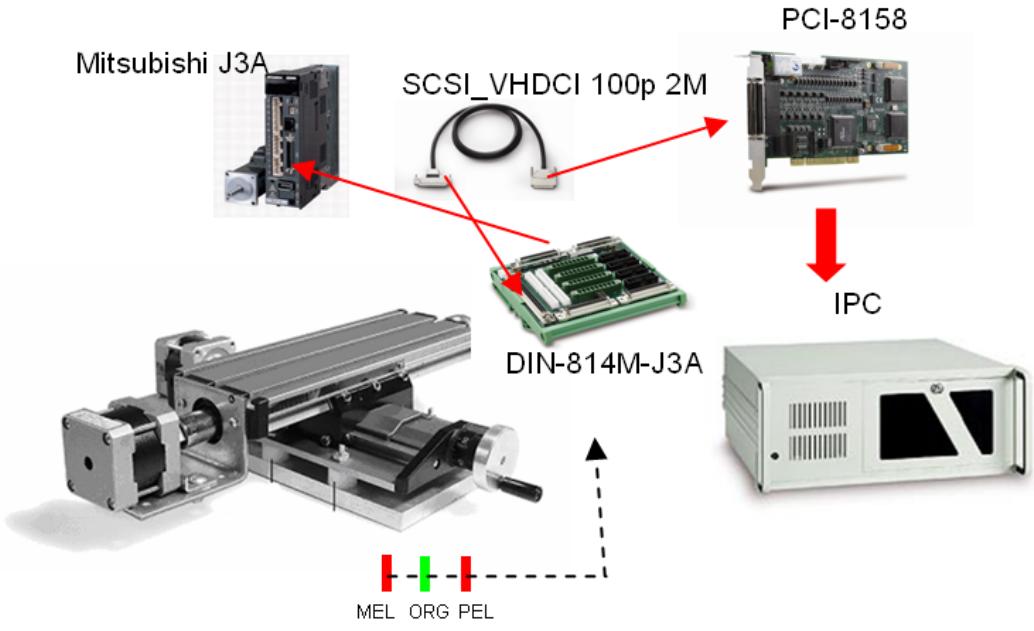
![Based on the provided image, here is the description of the labeled blocks and their connections:\n\n**Labeled Blocks:**\n*   **Mitsubishi J3A** (Top Left)\n*   **SCSI_VHDCI 100p 2M** (Top Center)\n*   **PCI-8158** (Top Right)\n*   **DIN-814M-J3A** (Center)\n*   **IPC** (Bottom Right)\n*   **MEL ORG PEL** (Bottom Center)\n\n**Connections:**\n*   **SCSI_VHDCI 100p 2M** connects via red arrows to **Mitsubishi J3A**, **PCI-8158**, and **DIN-814M-J3A**.\n*   **PCI-8158** connects via a red arrow downward to **IPC**.\n*   A black dashed arrow originates near the **PEL** label (part of **MEL ORG PEL**) and points upward toward the linear actuator assembly shown at the bottom left.](.pci-8158-manual-10/c19d30b678b29dc4c087671cd2fcccb3f0d3bf9ce94cadb63d22530732336eed.jpg)

# 7.2 Terminal Board User Guide

Please refer the individual user guide of terminal board. The supported terminal boards are as follows:

<table><tr><td>Mitsubishi J2 Super</td><td>DIN-814M</td></tr><tr><td>Mitsubishi J3A</td><td>DIN-814M-J3A</td></tr><tr><td>Yaskawa Sigma II</td><td>DIN-814Y</td></tr><tr><td>Panasonic MINAS A4</td><td>DIN-814P-A4</td></tr></table>

# Warranty Policy

Thank you for choosing ADLINK. To understand your rights and enjoy all the after-sales services we offer, please read the following carefully.

1. Before using ADLINK's products please read the user manual and follow the instructions exactly. When sending in damaged products for repair, please attach an RMA application form which can be downloaded from: http://rma.adlinktech.com/policy/.
2. All ADLINK products come with a limited two-year warranty, one year for products bought in China:

The warranty period starts on the day the product is shipped from ADLINK's factory.
▶ Peripherals and third-party products not manufactured by ADLINK will be covered by the original manufacturers' warranty.
For products containing storage devices (hard drives, flash cards, etc.), please back up your data before sending them for repair. ADLINK is not responsible for any loss of data.
▶ Please ensure the use of properly licensed software with our systems. ADLINK does not condone the use of pirated software and will not service systems using such software. ADLINK will not be held legally responsible for products shipped with unlicensed software installed by the user.
For general repairs, please do not include peripheral accessories. If peripherals need to be included, be certain to specify which items you sent on the RMA Request & Confirmation Form. ADLINK is not responsible for items not listed on the RMA Request & Confirmation Form.

3. Our repair service is not covered by ADLINK's guarantee in the following situations:

▶ Damage caused by not following instructions in the User's Manual.
▶ Damage caused by carelessness on the user's part during product transportation.
▶ Damage caused by fire, earthquakes, floods, lightening, pollution, other acts of God, and/or incorrect usage of voltage transformers.
▶ Damage caused by unsuitable storage environments (i.e. high temperatures, high humidity, or volatile chemicals).
▶ Damage caused by leakage of battery fluid during or after change of batteries by customer/user.
▶ Damage from improper repair by unauthorized ADLINK technicians.
▶ Products with altered and/or damaged serial numbers are not entitled to our service.
▶ This warranty is not transferable or extendible.
▶ Other categories not protected under our warranty.

4. Customers are responsible for shipping costs to transport damaged products to our company or sales office.

5. To ensure the speed and quality of product repair, please download an RMA application form from our company website: http://rma.adlinktech.com/policy. Damaged products with attached RMA forms receive priority.

If you have any further questions, please email our FAE staff: service@adlinktech.com.
[🔗 Link to the original document](.pci-8158-manual-10/pci-8158-manual-10.pdf)
