# PCIe-833x Series

# PCIe-8332/PCIe-8334/PCIe-8338

PCIe EtherCAT

Master Motion Controller

User’s Manual

Manual Rev.: 1.1

Revision Date: May 28, 2019

Part No: 50-11179-1010

# Revision History

<table><tr><td>Revision</td><td>Release Date</td><td>Description of Change(s)</td></tr><tr><td>1.0</td><td>Apr. 10, 2019</td><td>Initial Release</td></tr><tr><td>1.1</td><td>May 28, 2019</td><td>Errata resolved</td></tr></table>

# Preface

# Copyright 2019 ADLINK Technology, Inc.

This document contains proprietary information protected by copyright. All rights are reserved. No part of this manual may be reproduced by any mechanical, electronic, or other means in any form without prior written permission of the manufacturer.

# Disclaimer

The information in this document is subject to change without prior notice in order to improve reliability, design, and function and does not represent a commitment on the part of the manufacturer.

In no event will the manufacturer be liable for direct, indirect, special, incidental, or consequential damages arising out of the use or inability to use the product or documentation, even if advised of the possibility of such damages.

# Environmental Responsibility

ADLINK is committed to fulfill its social responsibility to global environmental preservation through compliance with the European Union's Restriction of Hazardous Substances (RoHS) directive and Waste Electrical and Electronic Equipment (WEEE) directive. Environmental protection is a top priority for ADLINK. We have enforced measures to ensure that our products, manufacturing processes, components, and raw materials have as little impact on the environment as possible. When products are at their end of life, our customers are encouraged to dispose of them in accordance with the product disposal and/or recovery programs prescribed by their nation or company.

# Trademarks

Product names mentioned herein are used for identification purposes only and may be trademarks and/or registered trademarks of their respective companies.

# Conventions

Take note of the following conventions used throughout this manual to make sure that users perform certain tasks and instructions properly.

![The image displays a digital icon of a document. It features a white sheet of paper with a folded top-left corner and horizontal gray lines running across it. A large, red checkmark is superimposed diagonally over the center of the paper.](.pcie-833x-50-11179-1010-11/7a3e8656ae9bad60869f551691dddc7e81c66b16845133949e7ad42dae286013.jpg)
NOTE:

Additional information, aids, and tips that help users perform tasks.

![A yellow triangular warning sign with a black border and a black exclamation point in the center.](.pcie-833x-50-11179-1010-11/87951f7a2f6c89fd3443e2c05a35ed0f7896c536bfa1f23213e107e1f7e0d04a.jpg)
CAUTION:

Information to prevent minor physical injury, component damage, data loss, and/or program corruption when trying to complete a task.

![The image displays a red triangle containing a large white exclamation point. Above the top of the triangle is a black horizontal line.](.pcie-833x-50-11179-1010-11/1f2b3b968278ba82d4d2774bc476ebd0e03c41bb8029f5a3ab1c3e288156d9b2.jpg)
WARNING:

Information to prevent serious physical injury, component damage, data loss, and/or program corruption when trying to complete a specific task.

# Table of Contents

# Preface .......... iii

# List of Tables ......... ... vii

# List of Figures ......... ix

# 1 Introduction ........

MotionCreatorPro 2™ . 2

Windows Programming Libraries . 2

EtherCAT Topology . . 3

1.1 Features... 3

1.2 Specifications...... 4

1.3 Supported Software ... 6

OS/Programming Library ... 6

APS Functions . 6

MotionCreatorPro 2 . 6

1.4 Available Terminal Board. 6

1.5 Exterior Profile .... 7

1.5.1 I/O Indicators .... 9

1.6 I/O Connectors.... 9

1.6.1 EtherCAT Connector ..... 9

1.6.2 EMG Connector... .. 10

1.6.3 DI/O Connector... ... 11

# 2 Getting Started ........ 1 3

2.1 Package Contents ..... 13

2.2 PCIe-833x Series Hardware Installation.... 1 3

Hardware Configuration .... .. 13

PCIe Slot Selection .... .. 13

Installation Procedures .. 13

Troubleshooting: ... .. 14

2.3 Software Driver Installation .... . 15
2.4 SW5 Card Index Selection..... 18
2.5 IDE 16p to DSUB 37p Bus....... 19
2.6 Signal Connection.... . 20

2.6.1 General Digital Output .. .... 20
2.6.2 General Digital Input & Pulsar Input ... .... 20
2.6.3 Emergency Stop Input (EMG)..... ... 22

# Important Safety Instructions....... . 23

# Getting Service ...... .. 27

# List of Tables

Table 1-1: PCB Connector Legend .. 8
Table 1-2: I/O Indicator Legend 9
Table 1-3: EtherCAT Connector Pin Assignments ....... 10
Table 1-4: EtherCAT Connector LED Legend 10
Table 1-5: EMG Connector Pin Assignments 10
Table 1-6: DI/O Connector Pin Assignments .... 11
Table 2-1: SW5 Card Index 19
Table 2-2: DSUB 37-pin Connector Pin Assignments ............. 20

This page intentionally left blank.

# List of Figures

Figure 1-1: PCIe-833x Series Block Diagram .. 2
Figure 1-2: PCB Layout .. 7
Figure 1-3: PCB Connectors.... 8
Figure 1-4: I/O Indicators ... . 9
Figure 2-1: SW5 Switch .... .. 18
Figure 2-2: DSUB 37-pin Connector .. .. 19

This page intentionally left blank.

# 1 Introduction

ADLINK’s PCIe-833x Series is a fully in-house developed ARM-based EtherCAT motion controller, supporting up to 64 synchronized axes and over 10,000 points simultaneously. The PCIe-833x Series features dedicated isolated emergency stop input (EMG), and configurable isolated high-speed digital input as not only generic sensor input but also pulse input with up to 1MHz input frequency. Maximum jitter performance is provided in the minimal cycle of 250µs to improve motion and I/O synchronous control in vertical automation applications such as semiconductor, electrical manufacturing systems, and others.

The PCIe-833x Series provides an out-of-shell applicationready function library (APS Function Library) to support multidimensional, highly synchronized, time-deterministic event triggering motion & I/O control. The broad AVL of EtherCAT 3rd party slaves enhances user design with ADLINK APS function library with flexible implementation in preferred 3rd party slaves. ADLINK's MotionCreatorPro 2™ motion control utility is fully supported in Microsoft® Windows™ environments, allowing users to complete motion, EtherCAT, and I/O configuration and function evaluation.

The PCIe-833x Series, as shown, uses one digital signal processor (ARM) from Xilinx SoC as its main computing unit and integrates high speed large volume Field Programmable Gate

Array (FPGA) to provide high speed pulsar input, emergency stop input (EMG) as well as 2/4 digital input and digital output.a

![The diagram centers on a large block labeled **Xilinx Zynq SoC**.\n\n**Top Connections:**\n*   A blue header block labeled **CN8** sits above, containing **4 x Digital Output** and **4 x Digital Input / Pulsar Input**.\n*   Below **4 x Digital Output**, a block labeled **Isolation** is connected via upward red arrows to the output block and the SoC.\n*   Below **4 x Digital Input / Pulsar Input**, a block labeled **High-Speed Isolation** is connected via downward red arrows from the input block and into the SoC.\n\n**Right-Side Connections:**\n*   Two **PHY** blocks connect bidirectionally (red double arrows) to the **Xilinx Zynq SoC**.\n*   Each **PHY** block connects bidirectionally (red double arrows) to **RJ45** blocks housed in vertical boxes labeled **ECAT0** and **ECAT1**.\n*   To the far right, a vertical dashed line labeled **CN5** encloses a block labeled **EMG**.\n*   A black arrow points left from **EMG** to a vertical **Isolation** block.\n*   A black arrow points left from that **Isolation** block to the **Xilinx Zynq SoC**.\n\n**Bottom Connection:**\n*   A bidirectional red arrow connects the bottom of the SoC to the text **PCI Express, Gen 1, x 1 Compliant**.](.pcie-833x-50-11179-1010-11/03c8e49f41ba864755e9b0e5f0f4f63fdf213b3f8418a1e88839f0f9a3696749.jpg)

Figure 1-1: PCIe-833x Series Block Diagram

# MotionCreatorPro 2™

Graphical motion control interface enables Windows-based motion control software development for EtherCAT configuration, motion control, and I/O status monitoring. Allows completioon of hardware installation and wiring in real-time signal feedback as well as step-by-step single-axis manipulation, saving development time and cost.

# Windows Programming Libraries

A Windows coding environment supporting Microsoft C#, Microsoft .NET framework based VB.NET, VC, NET and Visual Studio C++ 6.0. Sample programs are provided.

# EtherCAT Topology

EtherCAT supports virtually all conncetivity topologies, inculding line, tree, star, and daisy-chain, making pure bus or line topology with hundreds of nodes possible, with none of the limitations that normally arise from cascading switches or hubs.

In system connection, the combination of lines with branches or drop lines is beneficial, since the ports necessary to create branches are directly integrated in multiple I/O modules, requiring no additional switches or active infrastructure components.

Additional flexibility is enabled for supported cable types. Inexpensive industrial Ethernet cable can be used between two nodes up to 100m apart in 100BASE-TX mode. The Power over EtherCAT option (compatible with IEEE 802.3af) enables connection of devices such as sensors with a single line. Fiber optics (such as 100BASE-FX) can also be used, for example for a node distance exceeding 100 m.

Up to 65,535 devices can be connected to EtherCAT, making network expansion is virtually unlimited, while normal Ethernet arbitrary changes between physical layers are allowed.

# 1.1 Features

 PCI Express® x 1 compliant
 Motion control of 16/32/64 axes & 10,000 I/O points via EtherCAT
 EtherCAT cycle time up to 250µs
 Broad AVL of EtherCAT slaves
 Point-table functions for contouring applications
 Support for up to 16D linear interpolations, 3D circular and 3D spiral interpolation
 Switchable card ID

# 1.2 Specifications

<table><tr><td></td><td>PCIe-8332</td><td>PCIe-8334</td><td>PCIe-8338</td></tr><tr><td colspan="4">System</td></tr><tr><td>Axes supported (max.)</td><td>16</td><td>32</td><td>64</td></tr><tr><td>Processor</td><td colspan="3">Xilinx Zynq SoC</td></tr><tr><td>Memory</td><td colspan="3">128MB DDR x 2</td></tr><tr><td colspan="4">EtherCAT Communication</td></tr><tr><td>EtherCAT Master Cycle Time</td><td colspan="3">250/500/1000/2000/4000μs (configurable)</td></tr><tr><td>Communication Fault Detection</td><td colspan="3">Yes</td></tr><tr><td>Max. I/O Points</td><td colspan="3">10,000</td></tr><tr><td colspan="4">I/O Interface</td></tr><tr><td>Digital Output Channel</td><td colspan="3">4</td></tr><tr><td>Digital Output Type</td><td colspan="3">Sinking</td></tr><tr><td>Digital Output Voltage</td><td colspan="3">24Vdc ±10%</td></tr><tr><td>Digital Output Current</td><td colspan="3">90mA</td></tr><tr><td>Digital Output Isolation Voltage</td><td colspan="3">2500Vrms</td></tr><tr><td>Digital Input Channel</td><td colspan="3">4 (2CH can be configured as Pulsar Input)</td></tr><tr><td>Digital Input Type</td><td colspan="3">Sourcing</td></tr><tr><td>Digital Input Voltage</td><td colspan="3">24Vdc ±10%</td></tr><tr><td>Digital Input Current</td><td colspan="3">50mA for DI0, DI115mA for DI2, DI3 (Pulse)</td></tr><tr><td>Digital Input Isolation Voltage</td><td colspan="3">2500Vrms</td></tr><tr><td>Pulsar Input Frequency</td><td colspan="3">1MHz</td></tr><tr><td>Pulsar Input Mode</td><td colspan="3">CW/CCW; 1x/2x/4x AB phase</td></tr><tr><td>EMG (Emergency Stop) Input</td><td colspan="3">Yes</td></tr><tr><td>EMG Input Type</td><td colspan="3">COM</td></tr><tr><td>EMG Input Voltage</td><td colspan="3">24Vdc ±10%</td></tr><tr><td>EMG Input Current</td><td colspan="3">50mA</td></tr><tr><td colspan="4">Power Consumption</td></tr><tr><td>Slot power supply (input)</td><td colspan="3">+12 VDC ±5%, 500 mA (max)</td></tr><tr><td colspan="4">Physical/Environmental</td></tr><tr><td>Dimensions</td><td colspan="3">100.36 mm x 151.90 mm (H x L)</td></tr><tr><td>Operating Temperature</td><td colspan="3">0°C to 50°C</td></tr><tr><td>Storage Temperature</td><td colspan="3">-20°C to 80°C</td></tr><tr><td>Humidity</td><td colspan="3">5% to 85% (non-condensing)</td></tr><tr><td>Safety</td><td colspan="3">EN 55022/24, CLASS B</td></tr><tr><td colspan="4">Motion</td></tr><tr><td>Speed Profile Planning</td><td colspan="3">Trapezoidal curve and S-curve</td></tr><tr><td>Point-to-Point Move</td><td colspan="3">Yes</td></tr><tr><td>Linear Interpolation</td><td colspan="3">2-16</td></tr><tr><td>Circular Interpolation</td><td>16</td><td>32</td><td>64</td></tr><tr><td>Spiral Interpolation</td><td>16</td><td>32</td><td>64</td></tr><tr><td>Helical Interpolation</td><td>16</td><td>32</td><td>64</td></tr><tr><td>Home Return</td><td colspan="3">User customization (Refer to zero-position, limit switch, EZ signals from Servo Drive)</td></tr><tr><td colspan="4">Continuous Motion</td></tr><tr><td>Point Table</td><td colspan="3">2x50 path length buffer for advance point table(64/32/16)x100 path length buffer for PT/PVT point table</td></tr><tr><td colspan="4">Advanced Motion</td></tr><tr><td>Gantry</td><td colspan="3">3 synchronous sets</td></tr><tr><td>EGearing</td><td colspan="3">3 synchronous sets</td></tr><tr><td>Interrupt</td><td colspan="3">Motion status event / error alarm / in position / emergency stop</td></tr><tr><td rowspan="4">Diagnostic</td><td colspan="3">Profile Sampling</td></tr><tr><td colspan="3">Motion Status</td></tr><tr><td colspan="3">Motion I/O Status</td></tr><tr><td colspan="3">Watch Dog Timer (WDT)</td></tr></table>

![The image displays a white document icon with a folded top-right corner and a black outline. Faint gray horizontal lines run across the page to simulate text. A large, bold red checkmark is superimposed over the left side of the document. There is no text in the image.](.pcie-833x-50-11179-1010-11/f70bfdf31c3bb9d461689189445fa2949aff6fcfc056340bfb1cf8cbb2f4a047.jpg)
NOTE:

Due to limitations in microprocessor power, the maximum number of EPS-7002 cards accommodated in one EPS-9905 chassis is 2.

# 1.3 Supported Software

# OS/Programming Library

The PCIe-833x Series supports Windows 10 64/32-bit OS and provides DLL files for easy application development by users.

# APS Functions

The PCIe-833x Series is fully compliant with the APS (Automation Product Software) function library, independent of programming languages and operating systems (OS). A complete detailed listing of functions can be found in the APS Function Library User Manual.

# MotionCreatorPro 2

MotionCreatorPro $2 ^ { \top \mathsf { M } }$ is a user interface exclusively developed for ADLINK motion control products in a standard Windows environment. It provides easy card and axis parameter setup, and a Setup Wizard guides users through hardware installation and wiring as well as single-axis manipulation in minutes. MotionCreatorPro 2™ not only effectively reduces development time but also enables concurrent validation of overall mechanism and electric design with all single axis and interpolation motion operation pages.

For more information, please see the ADLINK document Motion-CreatorPro 2 User’s Manual.

# 1.4 Available Terminal Board

ADLINK's optional DIN-37D terminal board (P/N 91-14025-1020) for the PCIe-833x Series provides DI/O I/O connectability, via ADLINK cable ACL-10137-1MM, with generic application sensors and actuators.

# 1.5 Exterior Profile

![The image displays an icon of a white document with a folded upper-left corner and faint horizontal gray lines running across it. A large, bold red checkmark is superimposed over the center of the document.](.pcie-833x-50-11179-1010-11/118fa16ff546ae539edd58e3553b9b9ddf44afbcca1580c0a92cc37d75b1bcf4.jpg)
NOTE:

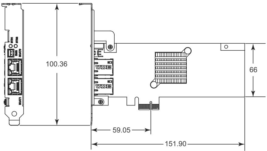
All dimensions shown are in millimeters (mm) unless otherwise stated.
![100.36\n59.05\n151.90\n66](.pcie-833x-50-11179-1010-11/5e8a2403b4b5cc7e32953e53f3e485b59a77c2d81fa771402e688f263ba4642f.jpg)

Figure 1-2: PCB Layout

![The image shows a white sheet of paper with a folded top-left corner. Faint horizontal gray lines run across the paper, resembling a list or document. A large, thick red checkmark is drawn diagonally across the paper, starting from the bottom left and ending near the top right.](.pcie-833x-50-11179-1010-11/e5be5ae48d9c4fbdc9108bd97c5ac26404a8c084e9c7a76c14b85321e038c99d.jpg)
NOTE:

SW5 Card ID switch is located on the PCB rear side and is thus not shown in the Figure
![B\nA\nC\nD\nUDE\nUDE](.pcie-833x-50-11179-1010-11/b984d7e82f218308369dac299ca5f6934b74f4602c973d6ab3a1389f64e65dc4.jpg)

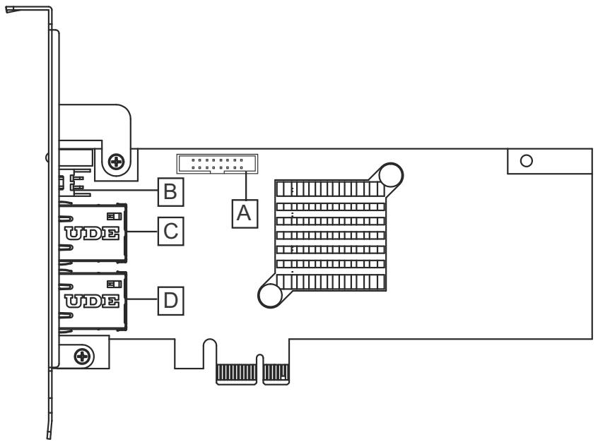
Figure 1-3: PCB Connectors

<table><tr><td></td><td>Location</td><td>Connector</td><td>Details</td></tr><tr><td>A</td><td>CN8</td><td>16-pin Box Header</td><td>8CH isolated digital I/O</td></tr><tr><td>B</td><td>EMG (CN5)</td><td>2-pin</td><td>Emergency stop signal input</td></tr><tr><td>C</td><td>ECAT0</td><td>RJ45</td><td>Basic EtherCAT communication</td></tr><tr><td>D</td><td>ECAT1</td><td>RJ45</td><td>Advanced EtherCAT communication</td></tr><tr><td>(not shown)</td><td>SW5</td><td>DIP switch</td><td>Card ID setup (0 to 15)</td></tr></table>

Table 1-1: PCB Connector Legend

# 1.5.1 I/O Indicators

![ECAT1\nEMG\nECAT0\nSTS1\nSTS2\nA\nB](.pcie-833x-50-11179-1010-11/3bdc09acd3b636e4074977fb66711144e228266cebb32b756470d91c85ebd9f1.jpg)

Figure 1-4: I/O Indicators

<table><tr><td></td><td>Indicator</td><td>Color</td><td>Function</td></tr><tr><td>A</td><td>STS1</td><td>Green</td><td>Lit when SoftMotionTM initializes</td></tr><tr><td>B</td><td>STS2</td><td>Red</td><td>Lit when emergency occurs</td></tr></table>

Table 1-2: I/O Indicator Legend

# 1.6 I/O Connectors

# 1.6.1 EtherCAT Connector

ECAT0 & ECAT1 (reserved)

![Yellow\nGreen\n8\n1](.pcie-833x-50-11179-1010-11/a2cfe2e30ea3827b2e3c1f7e88876105510f3114076523ff392bd9f69b2ace99.jpg)

<table><tr><td>Pin</td><td>Signal</td></tr><tr><td>1</td><td>TX+</td></tr></table>

<table><tr><td>Pin</td><td>Signal</td></tr><tr><td>2</td><td>TX-</td></tr><tr><td>3</td><td>RX+</td></tr><tr><td>4</td><td>NC</td></tr><tr><td>5</td><td>NC</td></tr><tr><td>6</td><td>RX-</td></tr><tr><td>7</td><td>NC</td></tr><tr><td>8</td><td>NC</td></tr></table>

Table 1-3: EtherCAT Connector Pin Assignments

<table><tr><td></td><td>Function</td><td>Display</td><td>Indication</td></tr><tr><td rowspan="2">Yellow</td><td rowspan="2">Activity</td><td>Unlit</td><td>No Activity</td></tr><tr><td>Flashing</td><td>Activity</td></tr><tr><td rowspan="2">Green</td><td rowspan="2">Link</td><td>Unlit</td><td>OFF</td></tr><tr><td>Lit</td><td>ON</td></tr></table>

Table 1-4: EtherCAT Connector LED Legend

# 1.6.2 EMG Connector

CN5

![Pure architectural floor plan lines without any text, numbers, or symbols](.pcie-833x-50-11179-1010-11/0080a5f7d9e38277e9a4913956f4d0f72a591e702a5b5ae886542f0a419f6eea.jpg)

<table><tr><td>Pin</td><td>Name</td><td>Function</td></tr><tr><td>1</td><td>COM</td><td>Common ground or power</td></tr><tr><td>2</td><td>EMG</td><td>Emergency signal</td></tr></table>

Table 1-5: EMG Connector Pin Assignments

# 1.6.3 DI/O Connector

CN8: General Digital Output and Digital Input (/Pulsar Input)

![9\n16\n8](.pcie-833x-50-11179-1010-11/d69f972d98c0f5b617fb8bd3e64e60d9bbc64b4f530bdd56e958c3af015d1c15.jpg)

<table><tr><td>Pin</td><td>Name</td><td>I/O</td><td>Function</td></tr><tr><td>1</td><td>E24V_</td><td>--</td><td>Isolation power Input, +24V</td></tr><tr><td>2</td><td>EGND_</td><td>--</td><td>Ext. power ground</td></tr><tr><td>3</td><td>DI0</td><td>I</td><td>Digital Input 0</td></tr><tr><td>4</td><td>DI1</td><td>I</td><td>Digital Input 1</td></tr><tr><td>5</td><td>PA_5V</td><td>I</td><td>5V Pulser A signal input</td></tr><tr><td>6</td><td>PB_5V</td><td>I</td><td>5V Pulser B signal input</td></tr><tr><td>7</td><td>DI2/PCOM_5V</td><td>I/--</td><td>Digital Input 2/ Pulser common</td></tr><tr><td>8</td><td>DI3/PCOM_5V</td><td>I/--</td><td>Digital Input 3/ Pulser common</td></tr><tr><td>9</td><td>EGND_</td><td>--</td><td>Ext. power ground</td></tr><tr><td>10</td><td>DO0</td><td>O</td><td>Digital Output 0</td></tr><tr><td>11</td><td>DO1</td><td>O</td><td>Digital Output 1</td></tr><tr><td>12</td><td>DO2</td><td>O</td><td>Digital Output 2</td></tr><tr><td>13</td><td>DO3</td><td>O</td><td>Digital Output 3</td></tr><tr><td>14</td><td>DICOM1</td><td>--</td><td>Isolation power Input, +24V</td></tr><tr><td>15</td><td>DICOM2</td><td>--</td><td>Isolation power Input, +24V</td></tr><tr><td>16</td><td>EGND_</td><td>--</td><td>Ext. power ground</td></tr></table>

Table 1-6: DI/O Connector Pin Assignments

This page intentionally left blank.

# 2 Getting Started

# 2.1 Package Contents

The package includes the following items:

 PCIe-833x Series card
 IDE 16p – DSUB 37p flat cable
 Product warranty card

![The image shows a graphic icon of a document page with a folded upper-left corner. Horizontal lines run across the page to simulate text. A large red checkmark is superimposed over the document.](.pcie-833x-50-11179-1010-11/703f0af43c3d9636a253eb6743f0aeb6360e6fab309c94040c6e09345776e911.jpg)
NOTE:

The terminal board is an optional accessory and is not included in the PCIe-833x Series package.

If any of these items are missing or damaged, contact the dealer. Save the shipping materials and carton to ship or store the product in the future.

# 2.2 PCIe-833x Series Hardware Installation

# Hardware Configuration

The PCIe-833x Series employs PCI Express Gen 2, the x1 Bus System BIOS can autoconfigure memory and IRQ channel. The terminal board DIN-37D provides connection to various sensors, actuators, and pulsar devices through the extension cable.

# PCIe Slot Selection

The PCIe-833x Series can be installed in any PCIe slot.

# Installation Procedures

1. Please read this manual carefully and set up the signal I/ O in the proper mode.
2. Turn off power to the computer and all relevant terminal boards, and install the PCIe-833x Series in any available PCIe x1/x4/x8 slot. The slot is normally black. Ensure

that proper ESD (electrostatic discharge) protection measures are in place.

3. Connect the DIN-37D terminal board to the PCIe-833x Series (if applicable) with DSUB 37p cable.
4. Connect the EtherCAT type servo drive and I/O with Ethernet cables (CAT5e is recommended).
5. Set up the servo or stepper drive with physical limit switch, zero-positioning, and any essential drive signals.
6. Turn on system power including computer power, relevant terminal board power, and 24VDC power.
7. Configure EtherCAT communication parameters via MotionCreatorPro 2™ and 3rd party utility as needed.
8. Verify all I/O signals and servo operations via MotionCreatorPro 2™.

![The image displays a standard warning symbol consisting of a red triangle with a white exclamation point in its center. Directly below the triangle, the text 'WARNING:' is printed in black capital letters.](.pcie-833x-50-11179-1010-11/858a175939494be0506c5725f4b15a5887fe1287aa9274b687bf3492a2041a2c.jpg)

Please ground the shielding end of the power terminal to reduce risk of electric shock and ensure product operation of electric appliances.
 Please disconnect the motor drive from its load before using the card for the first time. Do not connect the motor drive to any mechanical devices before completion of the installation and fine tuning of the control system. Connect the system only after the board is adjusted and the drive parameters can control the motor.

# Troubleshooting:

If the computer fails to power up normally or the motion control system operates abnormally after system installation, follow the steps listed for troubleshooting. If the problem persists, please contact your dealer for technical services.

<table><tr><td>Problem</td><td>Possible Solve</td></tr><tr><td>The card does not appear in Windows Device Manager after its driver has been installed</td><td>Turn off the computer and ensure the card is properly mounted in the PCIe slot; ensure the driver is properly installed in Windows Control Panel&#x27;s Add/remove programs</td></tr><tr><td>MotionCreatorPro 2TM will not launch after driver installation.</td><td>Ensure .NET framework v3.5 or later has been installed.</td></tr><tr><td>The No Signal indicator in MotionCreatorPro 2TM appears after the motor is connected and the motor will not function</td><td>Ensure 24VDC power is provided, Ethernet cable connection is in place among EtherCAT devices, and that physical servo I/O signals are connected properly</td></tr><tr><td>EtherCAT slaves (incl. servo/ stepper drive or I/O) in MotionCreatorPro 2TM will not connect</td><td>Ensure all Ethernet cables connect all EtherCAT slave devices properly and every slave device is turned on for connection. The CAT5e cable is recommended for best impedance matching.</td></tr><tr><td>When using the MotionCreatorPro2TM all the control indicators of the drive light correctly but the drive warns</td><td>Ensure correctness of the axis parameter setup, alarm logic (ALM), and the EMG loop configuration</td></tr><tr><td>Value of output command differs from the encoder feedback value.</td><td>Ensure feedback signal (CW/CCW, 1xAB, 2xAB, 4xAB) settings comply with that of the drive</td></tr><tr><td>During motion control, the motor only moves in one direction rather than two</td><td>Ensure signal patterns (CW/CCW, OUT/ DIR) comply with that of the motor drive</td></tr></table>

# 2.3 Software Driver Installation

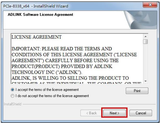
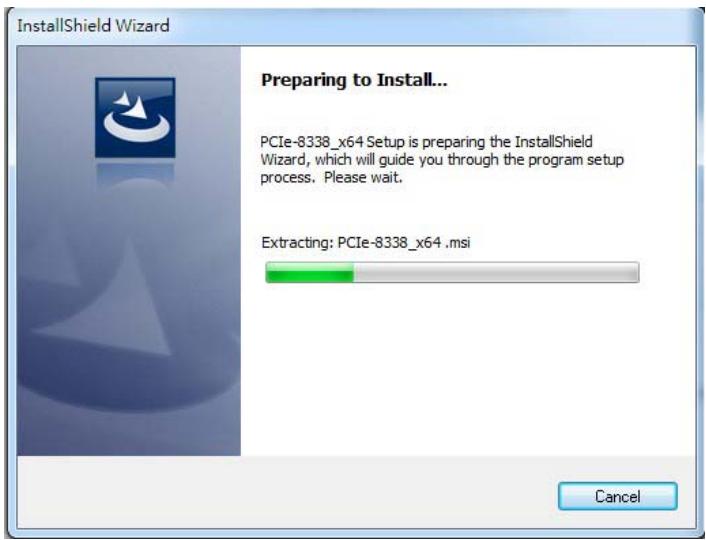
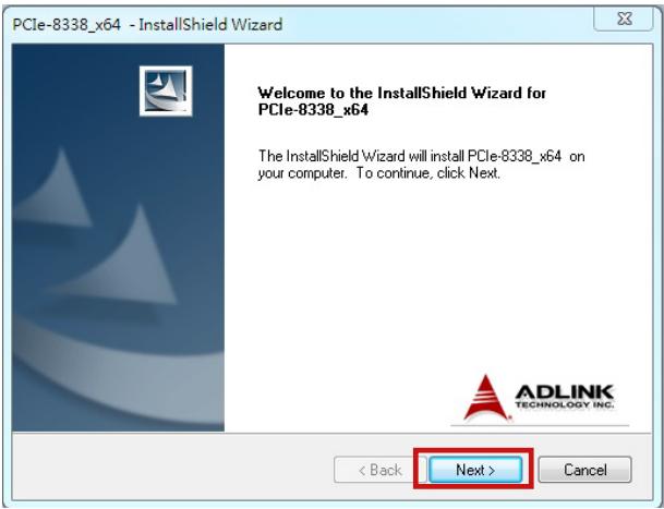
1. Download the PCIe-833x Series WDM file from ADLINK and run. Installation executes automatically.

2. Select Next as prompted to complete installation.
![PCIe-8338_x64 - InstallShield Wizard\nWelcome to the InstallShield Wizard for PCIe-8338_x64\nThe InstallShield Wizard will install PCIe-8338_x64 on your computer. To continue, click Next.\n( Back	Next )	Cancel](.pcie-833x-50-11179-1010-11/166c2cca3197150fd7b9a37865165a9579f05828a32a5f3fa91e0dd4f1c17962.jpg)

![PCIe-8338_x64 - InstallShield Wizard\nADLINK Software License Agreement\nLICENSE AGREEMENT\nIMPORTANT: PLEASE READ THE TERMS AND\nCONDITIONS OF THIS LICENSE AGREEMENT ('LICENSE\nAGREEMENT') CAREFULLY BEFORE USING THE\nPRODUCT(PRODUCT) PROVIDED BY ADLINK\nTECHNOLOGY INC ('ADLINK').\nADLINK, IS WILLING TO SELLING THE PRODUCT TO\nCUSTOMER AS THE INDIVIDUAL, THE COMPANY, OR THE\n• I accept the terms of the license agreement\n• I do not accept the terms of the license agreement\nInstallShield\n( Back	Next )	Cancel](.pcie-833x-50-11179-1010-11/ed25a5bcbd9c5b0e74bafd0c91202dd6fa81ef141d6f8b22605642ef969e5c7b.jpg)

![InstallShield Wizard\nPreparing to Install...\nPCIe-8338_x64 Setup is preparing the InstallShield Wizard, which will guide you through the program setup process. Please wait.\nExtracting: PCIe-8338_x64 .msi\nCancel](.pcie-833x-50-11179-1010-11/d18adf0b423e2c70305fda7bb0341ab791bbb12498de32421b9a76ba56c85674.jpg)

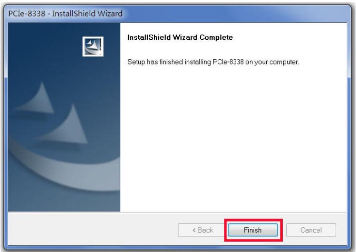
3. After installation is complete, select Finish.
![PCIe-8338 - InstallShield Wizard\nInstallShield Wizard Complete\nSetup has finished installing PCIe-8338 on your computer.\n( Back	Finish	Cancel](.pcie-833x-50-11179-1010-11/d3eeb3dd875791c757d632e84f80636554edaa6fb4e5240cb8ef1d9c049dbc6d.jpg)

4. Ensure the Windows Device Manager lists the PCIe-833x Series correctly.

5. Restart the computer now, or later, as desired.

![The image shows an icon of a white document with a folded top-right corner and faint horizontal lines, overlaid with a large red checkmark.](.pcie-833x-50-11179-1010-11/7be8f54f4f915359cbf57fa675ee848c5f1235e6e358a611ea1f44a6a98f5956.jpg)
NOTE:

Please download the latest installation software from ADLINK's official website to maintain an optimum operating environment.

http://www.adlinktech.com/Motion-Control/index.php

# 2.4 SW5 Card Index Selection
![ON DIP\n36\n1 2 3 4](.pcie-833x-50-11179-1010-11/c92c87dcca7e1bdccc70f749c3b891976288ee13b9193ff2ec0ed9c408935e60.jpg)

Figure 2-1: SW5 Switch

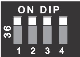
The SW5 switch is used to set the card index. For example, if the switch is set to 1-0-0-0 (ON-OFF-OFF-OFF), card ID is 1. The index value can be from 0 to 15. Details are as follows.

<table><tr><td>Card ID</td><td>Switch Setting (ON=1)</td></tr><tr><td>0</td><td>0000</td></tr><tr><td>1</td><td>1000</td></tr><tr><td>2</td><td>0100</td></tr><tr><td>3</td><td>1100</td></tr><tr><td>4</td><td>0010</td></tr><tr><td>5</td><td>1010</td></tr><tr><td>6</td><td>0110</td></tr><tr><td>7</td><td>1110</td></tr><tr><td>8</td><td>0001</td></tr><tr><td>9</td><td>1001</td></tr><tr><td>10</td><td>0101</td></tr><tr><td>11</td><td>1101</td></tr><tr><td>12</td><td>0011</td></tr><tr><td>13</td><td>1011</td></tr></table>

<table><tr><td>Card ID</td><td>Switch Setting (ON=1)</td></tr><tr><td>14</td><td>0111</td></tr><tr><td>15</td><td>1111</td></tr></table>

Table 2-1: SW5 Card Index

# 2.5 IDE 16p to DSUB 37p Bus

An IDE cable connecting IDE 16-pin to DSUB 37-pin, it allows the PCIe-833x Series to support Px extension 4CH digital input and 4CH digital output.

![19\n1\n37\n20](.pcie-833x-50-11179-1010-11/2accb2abbbfc9482b82399a35448fa7cba3e71076b796f6c05669e5a05c45eba.jpg)

Figure 2-2: DSUB 37-pin Connector

<table><tr><td>Pin</td><td>Name</td><td>Pin</td><td>Name</td></tr><tr><td>1</td><td>N/A</td><td>20</td><td>N/A</td></tr><tr><td>2</td><td>N/A</td><td>21</td><td>N/A</td></tr><tr><td>3</td><td>N/A</td><td>22</td><td>N/A</td></tr><tr><td>4</td><td>N/A</td><td>23</td><td>N/A</td></tr><tr><td>5</td><td>N/A</td><td>24</td><td>N/A</td></tr><tr><td>6</td><td>E24V_</td><td>25</td><td>EGND</td></tr><tr><td>7</td><td>EGND</td><td>26</td><td>DO0</td></tr><tr><td>8</td><td>DI0</td><td>27</td><td>DO1</td></tr><tr><td>9</td><td>DI1</td><td>28</td><td>DO2</td></tr><tr><td>10</td><td>PA_5V</td><td>29</td><td>DO3</td></tr><tr><td>11</td><td>PB_5V</td><td>30</td><td>DICOM1</td></tr><tr><td>12</td><td>DI2/PCOM_5V</td><td>31</td><td>DICOM2</td></tr></table>

<table><tr><td>Pin</td><td>Name</td><td>Pin</td><td>Name</td></tr><tr><td>13</td><td>DI3/PCOM_5V</td><td>32</td><td>EGND</td></tr><tr><td>14</td><td>N/A</td><td>33</td><td>N/A</td></tr><tr><td>15</td><td>N/A</td><td>34</td><td>N/A</td></tr><tr><td>16</td><td>N/A</td><td>35</td><td>N/A</td></tr><tr><td>17</td><td>N/A</td><td>36</td><td>N/A</td></tr><tr><td>18</td><td>N/A</td><td>37</td><td>N/A</td></tr><tr><td>19</td><td>N/A</td><td></td><td></td></tr></table>

Table 2-2: DSUB 37-pin Connector Pin Assignments

# 2.6 Signal Connection

# 2.6.1 General Digital Output

PCIe-833x Series provides 4 isolated digital output channels to connect 24VDC actuators such as electronic vacuums, valves and others. Sample signal wiring is shown.

![3.3V\nFPGA\nPS2802\nDO0-3\nEGND](.pcie-833x-50-11179-1010-11/238d8a62883b53226a767332b06fbf9641c254a503f7c9cb869e6bb65d69aacc.jpg)

# 2.6.2 General Digital Input & Pulsar Input

The PCIe-833x Series provides 4 isolated digital input channels to connect 24VDC sensors, in which the first two channels are configured for pulsar input. An example signal wiring is shown.

![E24V\n4.7kΩ\nPS2805\n3.3V\nDI0-1\nFPGA](.pcie-833x-50-11179-1010-11/610d35ed755ee0efbdfb391cc18fdc9a21f37c81a1727739617d1455dff8520b.jpg)

Connection of a pulsar device with 5V power supply (if selected) is shown. The pulsar input frequency supports up to 1MHz in variant input modes that include CW/CCW mode and 1x/2x/4x AB phase modes.

![DICOM1\nPA_5V\n2.32kΩ\n330Ω\nHCPL0631\nDI2/PCOM_5V\nDICOM2\nPB_5V\n2.32kΩ\n330Ω\nHCPL0631\nDI3/PCOM_5V\nFPGA](.pcie-833x-50-11179-1010-11/1877d602a94665762f981d1b759dd91c2b7f24d070447c818b2d01abede00358.jpg)

# 2.6.3 Emergency Stop Input (EMG)

The EMG signal identifies emergency stop input occurrence results in all motion functions forced to stop, while EtherCAT communication is retained for status monitoring.

![FPGA\n74LVC2G\n17\n3.3V\nPS2805\n2.32kΩ\nCOM\nEMG](.pcie-833x-50-11179-1010-11/03866c64119d1dd3abeadae98423629bbc6d7bbab1656c64a20607f20a860241.jpg)

# Important Safety Instructions

For user safety, please read and follow all instructions, Warnings, Cautions, and Notes marked in this manual and on the associated device before handling/operating the device, to avoid injury or damage.

S'il vous plaît prêter attention stricte à tous les avertissements et mises en garde figurant sur l'appareil , pour éviter des blessures ou des dommages.

 Read these safety instructions carefully
 Keep the User’s Manual for future reference
 Read the Specifications section of this manual for detailed information on the recommended operating environment
 The device can be operated at an ambient temperature of 50ºC
When installing/mounting or uninstalling/removing device; or when removal of a chassis cover is required for user servicing (See “Getting Started” on page 13.):

 Turn off power and unplug any power cords/cables
 Reinstall all chassis covers before restoring power

 To avoid electrical shock and/or damage to device:

 Keep device away from water or liquid sources
 Keep device away from high heat or humidity
 Keep device properly ventilated (do not block or cover ventilation openings)
 Always use recommended voltage and power source settings
 Always install and operate device near an easily accessible electrical outlet
 Secure the power cord (do not place any object on/over the power cord)
 Only install/attach and operate device on stable surfaces and/or recommended mountings

If the device will not be used for long periods of time, turn off and unplug from its power source

Never attempt to repair the device, which should only be serviced by qualified technical personnel using suitable tools
 A Lithium-type battery may be provided for uninterrupted backup or emergency power.

![The image displays a yellow triangular warning sign with a black border. Inside the triangle is a black exclamation point. Below the triangle, the text 'CAUTION:' appears in black capital letters.](.pcie-833x-50-11179-1010-11/a831150ada9c79cdc59124a03f29142b46d2f9d5875aeacf132c4bb9b4e752b8.jpg)

Risk of explosion if battery is replaced with one of an incorrect type; please dispose of used batteries appropriately.

Risque d’explosion si la pile est remplacée par une autre de type incorrect. Veuillez jeter les piles usagées de façon appropriée.

 The device must be serviced by authorized technicians when:

 The power cord or plug is damaged
 Liquid has entered the device interior
 The device has been exposed to high humidity and/or moisture
 The device is not functioning or does not function according to the User’s Manual
 The device has been dropped and/or damaged and/or shows obvious signs of breakage

Disconnect the power supply cord before loosening the thumbscrews and always fasten the thumbscrews with a screwdriver before starting the system up

 It is recommended that the device be installed only in a server room or computer room where access is:

 Restricted to qualified service personnel or users familiar with restrictions applied to the location, reasons therefor, and any precautions required

 Only afforded by the use of a tool or lock and key, or other means of security, and controlled by the authority responsible for the location

![Yellow triangular warning sign with black smoke symbol indicating heating or hazard](.pcie-833x-50-11179-1010-11/9e822db308531471faffd6257a6816bf2d1d15d92460bd0b9ced266516612665.jpg)

# BURN HAZARD

Touching this surface could result in bodily injury. To reduce risk, allow the surface to cool before touching.

# RISQUE DE BRÛLURES

Ne touchez pas cette surface, cela pourrait entraîner des blessures.

Pour éviter tout danger, laissez la surface refroidir avant de la toucher.

This page intentionally left blank.

# Getting Service

Ask an Expert: http://askanexpert.adlinktech.com

# ADLINK Technology, Inc.

9F, No.166 Jian Yi Road, Zhonghe District

New Taipei City 235, Taiwan

Tel: +886-2-8226-5877

Fax: +886-2-8226-5717

Email: service@adlinktech.com

# Ampro ADLINK Technology, Inc.

5215 Hellyer Avenue, #110

San Jose, CA 95138, USA

Tel: +1-408-360-0200

Toll Free: +1-800-966-5200 (USA only)

+1-408-360-0222

Email: info@adlinktech.com

# ADLINK Technology (China) Co., Ltd.

300 Fang Chun Rd., Zhangjiang Hi-Tech Park

Pudong New Area, Shanghai, 201203 China

Tel: +86-21-5132-8988

Fax: +86-21-5132-3588

Email: market@adlinktech.com

# LiPPERT ADLINK Technology GmbH

Hans-Thoma-Strasse 11

D-68163 Mannheim, Germany

Tel: +49-621-43214-0

Fax: +49-621 43214-30

Email: emea@adlinktech.com

Please visit the Contact page at www.adlinktech.com for information on how to contact the ADLINK regional office nearest you:
[🔗 Link to the original document](.pcie-833x-50-11179-1010-11/pcie-833x-50-11179-1010-11.pdf)