# GIE62+

# 2-CH PoE Gigabit Ethernet Vision

# (GigE Vision) Interface Card

# User’s Manual

Manual Rev. 2.00

Revision Date: November 19, 2009

Part No: 50-11168-1000

![This is a black and white image of the universal recycling symbol. It consists of a black circle containing three white arrows arranged in a triangular formation. The arrows are chasing each other in a clockwise direction, and each arrow features three horizontal lines running through its center.](.pcie-gie62-50-11168-1000-004/a0b2151f1867c1a9e34b01a3090b357591a70ff9fcd780fdb555ed93624b89d9.jpg)
Recycled Paper

Copyright 2009 ADLINK TECHNOLOGY INC.

All Rights Reserved.

The information in this document is subject to change without prior notice in order to improve reliability, design, and function and does not represent a commitment on the part of the manufacturer.

In no event will the manufacturer be liable for direct, indirect, special, incidental, or consequential damages arising out of the use or inability to use the product or documentation, even if advised of the possibility of such damages.

This document contains proprietary information protected by copyright. All rights are reserved. No part of this manual may be reproduced by any mechanical, electronic, or other means in any form without prior written permission of the manufacturer.

# Trademarks

Product names mentioned herein are used for identification purposes only and may be trademarks and/or registered trademarks of their respective companies.

# Getting Service

Contact us should you require any service or assistance.

# ADLINK Technology Inc.

Address: 9F, No.166 Jian Yi Road, Chungho City, Taipei County 235, Taiwan ؀קᗼխࡉؑ৬ԫሁ 166 ᇆ 9 ᑔ

Tel: +886-2-8226-5877

Fax: +886-2-8226-5717

Email: service@adlinktech.com

# Ampro ADLINK Technology Inc.

Address: 5215 Hellyer Avenue, #110, San Jose, CA 95138, USA

Tel: +1-408-360-0200

Toll Free: +1-800-966-5200 (USA only)

Fax: +1-408-360-0222

Email: info@adlinktech.com

# ADLINK Technology Beijing

Address: ࣫ҀᏖ⍋⎔ऎϞഄϰ䏃 1োⲜ߯ ࡯ࡼ ໻ॺ Eᑻ 801ᅸ (100085) Rm. 801, Power Creative E, No. 1, B/D Shang Di East Rd., Beijing 100085, China

Tel: +86-10-5885-8666

Fax: +86-10-5885-8625

Email: market@adlinktech.com

# ADLINK Technology Shanghai

Address: Ϟ⍋Ꮦⓩ⊇⋒催⾥ᡔᓔথऎ䩺∳䏃 333 ো 39 ᐶ 4 ሖ (200233)

Tel: +86-21-6495-5210

Fax: +86-21-5450-0414

Email: market@adlinktech.com

# ADLINK Technology Shenzhen

Address: ⏅ഇᏖफቅऎ⾥ᡔುफऎ催ᮄफϗ䘧᭄ᄫᡔᴃು A1 ᷟ 2 ὐ C ऎ (518057) 2F, C Block, Bld. A1, Cyber-Tech Zone, Gao Xin Ave. Sec 7, High-Tech Industrial Park S. Shenzhen, 518054 China

Tel: +86-755-2643-4858

Fax: +86-755-2664-6353

Email: market@adlinktech.com

# ADLINK Technology Inc. (German Liaison Office)

- 




 

!"   

#\$ %\$&'()\*(


# ADLINK (French Liaison Office)

-  #\$+
'
,---."!(

 

/01
 11

!" 

/01
 11

#\$ (%\$&'()\*(


# ADLINK Technology Japan Corporation

-   ᧲੩ㇺᷦ⼱඙ᐈ䊱⼱

 ᦺᣣ↢๮ᐈ䊱⼱䊎䊦 2!

-)\$\$\$3'4+4\*2!

3'4-)\$5&
&
 67

 2



!" 2

1

#\$ 87%\$&'()\*(


# ADLINK Technology Inc. (Korean Liaison Office)

- 昢殾柢 昢爎割 昢爎壟 1  穢壊 +9 猻

!3
+9 1 -
()

4

-
()
-

:


 2  1

!" 2  1

#\$ &
%\$&'()\*(


# ADLINK Technology Singapore Pte Ltd.

- 2'\$4;&lt;-\$'
\$4'

-\$47

 2

 1 121

!" 1 121

#\$ \$47
%\$&'()\*(


# ADLINK Technology Singapore Pte Ltd. (Indian Liaison Office

- 
\*
 =-7=-\$-
5\$
,4')


6&gt;	4>)?+4
 12?\$

 21 1 2

2
 2

#\$ \$\$%\$&'()\*(


# Table of Contents

# List of Tables ......... i

# List of Figures ......... iii

# 1 Introduction .....

1.1 Features... 2
1.2 Applications .... 2

# 2 Hardware Reference....... 3

2.1 GIE62+ .. 3

GIE62+ Specifications . 3
GIE62+ Connectors & Pin Definitions .... . 4

# 3 Installation Guide ..... 1 9

3.1 Hardware Installation .... 19
3.2 Driver Installation .... 20

# 4 Function Library ......... 29

4.1 Function List . 29
4.2 Functions ... 30

GiE62\_Initialize . .. 30
GiE62\_GetTotalDeviceNum .. 31
GiE62\_GetTotalDeviceID . 32
GiE62\_OpenDevice . .. 33
GiE62\_ResetDevice . 34
GiE62\_GetFirmwareVersion . . 35
GiE62\_SetDOStatus ... .. 36
GiE62\_GetDIStatus .... . 37
GiE62\_SetTriggerDelayTime .. .. 38
GiE62\_SetTriggerOutWidth . 39
GiE62\_SetTriggerOutPolarity . 40
GiE62\_SetTriggerInPolarity .... .. 41
GiE62\_GetTriggerDelayTime .. 42
GiE62\_GetTriggerOutWidth ... .. 43
GiE62\_GetTriggerOutPolarity .. 44
GiE62\_GetTriggerInPolarity .... .. 45

# 4.3 Error Codes .. 46

# List of Tables

Table 2-1: J2 RJ-45: LAN 1 Port . 5

Table 2-2: LAN status LED 5

Table 2-3: SW1: Card ID Select . 6

Table 2-4: Card ID Select Table 6

Table 2-5: SW2: PoE Function Select

Table 2-6: CN3: GPIO & Trigger ..... 8

Table 2-7: CN3: GPIO & Trigger ..... 8

Table 2-8: CN3: Power Connector .. 9

Table 2-9: Hardware Features 1 6

Table 4-1: Error Codes 46

# List of Figures

Figure 2-1: GIE62+ Layout . 4

# 1 Introduction

The ADLINK GIE62+ is a PCI Express® x4 lane frame grabber that supports two Power over Ethernet cameras and delivers unprecedented image acquisition rates of up to 2 Gbps and long cable distances of up to 100 m. The GIE62+ supports Power over Ethernet (PoE) to simplify installation, lower maintenance costs, and reduce the total cost of ownership.

The ADLINK GIE62+ supports the Link aggregation control protocol, offering an inexpensive way to set up a double-speed backbone network that transfers much more data than any one single Gigabit Ethernet port or device.

The GIE62+ is also ideal for automation applications by providing two of each isolated TTL digital inputs, outputs, and programmable trigger output pulses to connect to external devices such as position sensors and strobe lighting.

# 1.1 Features

 IEEE802.3af (48 V,15.4 W/channel) compliant
 Supports two independent GbE ports
 Supports Link aggregation
 Supports jumbo frames (9.5 KByte)
 PCI Express x4 compliant
 Provides Industrial screw lock connector
 2 isolation digital inputs/outputs
 2 isolation TTL level programmable trigger output pulses

# 1.2 Applications

 Machine Vision Inspection System
 Scientific Research Instrumentation
 Medical Research Instrumentation

# 2 Hardware Reference

# 2.1 GIE62+

# 2.1.1 GIE62+ Specifications

# Power over Ethernet Port

Two full-integrated Gigabit Ethernet Media Access Control (MAC) and physical layer (PHY) ports.
 The Power over Gigabit Ethernet Controller complies with the IEEE 802.3.af standard for a minimum of 15.4 watts with power up to 48 V over the existing CAT-5 Ethernet infrastructure without the need to make any modifications.
The Power over Gigabit Ethernet Controller provides a standard IEEE 802.3 Ethernet interface for 1000BASE-T, 100BASE-TX, and 10BASE-T applications (802.3, 802.3u, and 802.3ab).
 9 kB jumbo frame support

# IO Triggers

 2 isolated digital inputs
 2 isolated digital outputs
 2 isolated trigger inputs
 2 isolated trigger outputs

# Isolated Voltage

 Rated Isolation Voltage 1000 V @ 60 seconds

# Form Factor

 PCI Express interface, x4 lanes

# Dimensions

 W x L: 129.5 x 111.15 mm

# Operating Environment

 Temperature: 0 to $5 5 ^ { \circ } \mathrm { C }$
 Humidity: 5 to 90% RHNC

# Storage Environment

 Temperature: 0 to $8 5 ^ { \circ } \mathrm { C }$
 Humidity: 0 to 95% RHNC

# Power Requirements

 Power from the PCIe slot:
 +12 V max @ 0.2 A
 +3.3 V max @ 1.5 A
 Power from power connector (CN3)
 +12V max @ 3A (when the two Power over Ethernet ports are fully loaded, each port consumes 15.4 W)

# 2.1.2 GIE62+ Connectors & Pin Definitions

![CN1\nLED2\nJ3\nSW2\nCN3\nLED1\nJ2\nSW1](.pcie-gie62-50-11168-1000-004/595474d5a590f748b0950a8bd30678a2c0508fbde777f2ef435f770e58752b94.jpg)

Figure 2-1: GIE62+ Layout

# J2, J3 RJ-45 Ethernet Port

 J2 RJ-45: LAN 1 Port
 J3 RJ-45: LAN 2 Port

![1\n8](.pcie-gie62-50-11168-1000-004/09c4b50612339608709e4e1a5fed1e98ef38b966aa8018b68cc7c1c6081aef78.jpg)

<table><tr><td>Pin</td><td>Signal</td><td>Pin</td><td>Signal</td></tr><tr><td>1</td><td>MDI0+(PoE_DC48V)</td><td>5</td><td>MDI2-(PoE_DC48V)</td></tr><tr><td>2</td><td>MDI0-(PoE_DC48V)</td><td>6</td><td>MDI1-(PoE_DC0V)</td></tr><tr><td>3</td><td>MDI1+(PoE_DC0V)</td><td>7</td><td>MDI3+(PoE_DC0V)</td></tr><tr><td>4</td><td>MDI2+(PoE_DC48V)</td><td>8</td><td>MDI3-(PoE_DC0V)</td></tr></table>

Table 2-1: J2 RJ-45: LAN 1 Port

LED1: LAN 1 status LED
LED2: LAN 2 status LED

![1\n2\n3\n4](.pcie-gie62-50-11168-1000-004/b40e2ce3420b4f73b67064c4946fa11816ec85ff9264eceead910e82f9311b7d.jpg)

<table><tr><td>LED (Yellow)</td><td>Status</td><td>Function</td></tr><tr><td rowspan="2">1Speed status</td><td>On</td><td>1000 Mbps</td></tr><tr><td>Off</td><td>1000 Mbps link off</td></tr><tr><td rowspan="2">2Speed status</td><td>On</td><td>100 Mbps</td></tr><tr><td>Off</td><td>100 Mbps link off</td></tr><tr><td rowspan="3">3Link status</td><td>ON</td><td>Data link</td></tr><tr><td>OFF</td><td>Data link off</td></tr><tr><td>Blinking</td><td>Data transfer in progress</td></tr><tr><td rowspan="2">4PoE status</td><td>On</td><td>PoE link</td></tr><tr><td>Off</td><td>PoE link off</td></tr></table>

Table 2-2: LAN status LED

# SW1: Card ID Select

The Card ID supports up to four cards

![1\n2\n3\n4](.pcie-gie62-50-11168-1000-004/ac61430d261ed862c2359c2e37c4e623ecaa5ccda513a11bc6fca8d33d546531.jpg)

<table><tr><td>Pin</td><td>Signal Name</td><td>Default</td></tr><tr><td>1</td><td>Board ID Select 0</td><td>ON</td></tr><tr><td>2</td><td>Board ID Select 1</td><td>ON</td></tr><tr><td>3</td><td>Not used</td><td>ON</td></tr><tr><td>4</td><td>Not used</td><td>ON</td></tr></table>

Table 2-3: SW1: Card ID Select

<table><tr><td>Card ID</td><td>Board ID Select 0</td><td>Board ID Select 1</td></tr><tr><td>0</td><td>ON</td><td>ON</td></tr><tr><td>1</td><td>OFF</td><td>ON</td></tr><tr><td>2</td><td>ON</td><td>OFF</td></tr><tr><td>3</td><td>OFF</td><td>OFF</td></tr></table>

Table 2-4: Card ID Select Table

SW2: PoE Function Select
![1\n2\n3\n4](.pcie-gie62-50-11168-1000-004/83a9710f81827118d6246fe8b716bb9ed2e75bbb98b7ddedca252a0943a345e2.jpg)

<table><tr><td>Pin</td><td>Signal Name</td><td>Default</td></tr><tr><td>1</td><td>Shut off +48 V supply</td><td>OFF</td></tr><tr><td>2</td><td>Not used</td><td>OFF</td></tr><tr><td>3</td><td>PoE 1 shutdown</td><td>OFF</td></tr><tr><td>4</td><td>PoE 2 shutdown</td><td>OFF</td></tr></table>

<table><tr><td>LAN Port</td><td>PoE Function</td><td>Shut Off +48V Supply</td><td>PoE 1 Shutdown</td><td>PoE 2 Shutdown</td></tr><tr><td rowspan="2">1</td><td>ON</td><td>OFF</td><td>OFF</td><td></td></tr><tr><td>OFF</td><td></td><td>ON</td><td></td></tr><tr><td rowspan="2">2</td><td>ON</td><td>OFF</td><td></td><td>OFF</td></tr><tr><td>OFF</td><td></td><td></td><td>ON</td></tr></table>

Table 2-5: SW2: PoE Function Select

# CN1: GPIO & Trigger

![15□ □ □ □ □ □ □ 1\n16□ □ □ □ □ □ □ 2](.pcie-gie62-50-11168-1000-004/6e29213b921b358537b00dda1285eb2282c2e8de8704904f1a96b8297a33a571.jpg)

<table><tr><td>PIN</td><td>PIN NAME</td><td>TYPE</td><td>PIN</td><td>PIN NAME</td><td>TYPE</td></tr><tr><td>1</td><td>In01</td><td>IN</td><td>2</td><td>Coml01</td><td>IN</td></tr><tr><td>3</td><td>In02</td><td>IN</td><td>4</td><td>Coml02</td><td>IN</td></tr><tr><td>5</td><td>Out01</td><td>OUT</td><td>6</td><td>ComO01</td><td>OUT</td></tr><tr><td>7</td><td>Out02</td><td>OUT</td><td>8</td><td>ComO02</td><td>OUT</td></tr><tr><td>9</td><td>TrgIn1</td><td>IN</td><td>10</td><td>TrgComl01</td><td>IN</td></tr><tr><td>11</td><td>TrgIn2</td><td>IN</td><td>12</td><td>TrgComl02</td><td>IN</td></tr><tr><td>13</td><td>TrgOut1</td><td>OUT</td><td>14</td><td>TrgOut2</td><td>OUT</td></tr><tr><td>15</td><td>Frame Ground</td><td>OUT</td><td>16</td><td colspan="2"></td></tr></table>

Table 2-6: CN3: GPIO & Trigger

The extension cable connector is a D-sub 15 pin female connector.

![8\n1\n15\n9](.pcie-gie62-50-11168-1000-004/61f023021d1eeb900d56baf59fa3fb228ff931e836e4d4b2b8812257ddeb3075.jpg)

<table><tr><td>PIN</td><td>PIN NAME</td><td>TYPE</td><td>PIN</td><td>PIN NAME</td><td>TYPE</td></tr><tr><td>1</td><td>In01</td><td>IN</td><td>9</td><td>Coml01</td><td>IN</td></tr><tr><td>2</td><td>In02</td><td>IN</td><td>10</td><td>Coml02</td><td>IN</td></tr><tr><td>3</td><td>Out01</td><td>OUT</td><td>11</td><td>ComO01</td><td>OUT</td></tr><tr><td>4</td><td>Out02</td><td>OUT</td><td>12</td><td>ComO02</td><td>OUT</td></tr><tr><td>5</td><td>TrgIn1</td><td>IN</td><td>13</td><td>TrgComl01</td><td>IN</td></tr><tr><td>6</td><td>TrgIn2</td><td>IN</td><td>14</td><td>TrgComl02</td><td>IN</td></tr><tr><td>7</td><td>TrgOut1</td><td>OUT</td><td>15</td><td>TrgOut2</td><td>OUT</td></tr><tr><td>8</td><td>Frame Ground</td><td>OUT</td><td colspan="3"></td></tr></table>

Table 2-7: CN3: GPIO & Trigger

CN3: Power Connector
![Pure electrical connector diagram without any text, numbers, or symbols](.pcie-gie62-50-11168-1000-004/266a04d4bc5f69c76ef8262542164ed241a01d98885bf9a081c7fd991ec26442.jpg)

<table><tr><td>Pin</td><td>Singal</td></tr><tr><td>1</td><td>+12V</td></tr><tr><td>2</td><td>GND</td></tr><tr><td>3</td><td>GND</td></tr><tr><td>4</td><td>NC</td></tr></table>

Table 2-8: CN3: Power Connector

Note: When using the PoE feature, CN3 must be connected to the power supply.

Trigger control setting flow chart
![The flowchart describes a process involving the GIE62+ driver, starting with initialization and configuration steps.\n\n**Labeled Blocks:**\n1.  **Load GIE62+ driver**\n    *   GiE62_Initialize()\n    *   GiE62_OpenDevice(in CardID)\n2.  **Set the delay time of the output triggers**\n    *   GiE62_SetTriggerDelayTime(int CardID, int port, int DelayTime)\n3.  **Set the width of the output triggers**\n    *   GiE62_SetTriggerWidth(int CardID, int port, int Width)\n4.  **Set the input and output polarity of the output triggers**\n    *   GiE62_SetTriggerPolarity(int CardID, int port, int Status)\n5.  **If user wants to change the feature of trigger out.** (Diamond shape)\n6.  **Trigger input signal**\n7.  **Trigger out**\n8.  A circle with a plus sign (+)\n\n**Connections:**\n*   An arrow points from the 'Load GIE62+ driver' block down to the 'Set the delay time of the output triggers' block.\n*   An arrow points from the 'Set the delay time...' block down to the 'Set the width...' block.\n*   An arrow points from the 'Set the width...' block down to the 'Set the input and output polarity...' block.\n*   An arrow points from the 'Set the input and output polarity...' block down to the diamond block ('If user wants to change the feature of trigger out.').\n*   **Loop:** An arrow exits the left side of the diamond block, goes up, and points into the left side of the 'Set the delay time of the output triggers' block.\n*   **Main Path:** An arrow exits the bottom of the diamond block and points down to the circle with a plus sign.\n*   **Input:** An arrow points from the 'Trigger input signal' block leftward into the circle with the plus sign.\n*   **Output:** An arrow exits the bottom of the circle with the plus sign and points down to the 'Trigger out' block.](.pcie-gie62-50-11168-1000-004/a79c43f5af3bd354299a97ea4f944a5c1b920962a715665f1b8c421766d172b1.jpg)

Digital Input Circuit
![Digital Input Circuit\nDC 3.3V\nDigital Input Common X\n1000ohm 3/4W\nDigital Input X\n0.1uF/50V\n1000pF/50V\nFrame GND](.pcie-gie62-50-11168-1000-004/6000b0431482cfed1c337dc05669e338c733bf8c16353d9f9d1b56ae62811b6a.jpg)

Digital Output Circuit

Digital Output Circuit
![Digital\nOutput X\nDigital Output\nCommon X\n1000pF/50V 0.1uF/50V](.pcie-gie62-50-11168-1000-004/17776b42cb4bdb2c5b79c079f444738717dc1bdba0e85d7238ad8e077c293e6d.jpg)

Trigger Input Circuit
![Trigger Input\nCommon X\n1000 ohm 3/4W\nTrigger Input X\n0.1uF/50V\n1000pF/50V\nFrame GND\nTrigger Input Circuit\nDC 3.3V](.pcie-gie62-50-11168-1000-004/a2404e1da02c046bcfdb0b09509f19d8df7fc38c1c4bb7d0d7140f0e86ab26f2.jpg)

Trigger Output Circuit
![Trigger Output Circuit\nDC 5V\n300 ohm 1/10W\nTrigger\nOutput X\nFrame Ground](.pcie-gie62-50-11168-1000-004/181ac2efe79744d05dcf7acc85ac9f616a4ad6e3769433a729644d7966aa50cb.jpg)

# Connection Sample with External I/O Device

 Digital input or trigger input connection for switch input.

![Digital or trigger input\nconnection sample for\nswitch input\nDC Power\nSupply\nSwitch\nPCIe-GIE62+ Internal Circuit\nDigital\nInput\nCommon X\nDigital\nInput X\nFrame GND\nDC 3.3V](.pcie-gie62-50-11168-1000-004/559813c3f5b089edad736955a20a388bc8d97e7a098d468fe2536df5fad952d6.jpg)

 Digital input or trigger input connection for TTL signal input.

Note: The response of the computer needs to be inversed in this connection condition mode. If the external device output controls the digital input common contact, the response of the computer must be inversed.

![Digital or trigger input\nconnection sample for TTL\nDevice input\nDC Power\nSupply\nTTL\nDevice\nOutput\nDigital\nInput X\nCommon X\nDigital\nInput X\nFrame GND\nPCIe-GIE62+ Internal Circuit\nDC 3.3V](.pcie-gie62-50-11168-1000-004/d72c4dcbef0cc1fc63b3f1c674bb022cf662207671fb17b43367283468c72173.jpg)

 Digital output connection for user device control.
![Digital output connection\nsample for user device\ncontrol\nUser\nDevice\nDC Power\nSupply\nDigital\nOutput X\nDigital Output\nCommon X\nPCIe-GIE62+ Internal Circuit\nMaximum of sink current is\n80 mA](.pcie-gie62-50-11168-1000-004/ec1b3634119dab1e986da4ebdd3b588a327525f4edcff1adb0b07f87485f8015.jpg)

 Digital output connection for a logic signal output.
![Digital output connection\nsample for a logic signal\noutput\nDC Power\nSupply\n+\n-\nUser\nDevice\ninput\nDigital\nOutput X\nDigital Output\nCommon X\nPCIe-GIE62+ Internal Circuit\nMaximum of sink current is\n80 mA](.pcie-gie62-50-11168-1000-004/7a2144ad89163a6f53490b89daf680c586cd661195cd8c66b0ca1f493cac1723.jpg)

 Trigger output connection for a trigger signal output.

![Trigger output connection\nsample for a trigger signal\noutput\nDC Power\nSupply\n+\n-\nUser\nDevice\ninput\nPCIe-GIE62+ Internal Circuit\nDC 5V\nTrigger\nOutput X\nFrame Ground](.pcie-gie62-50-11168-1000-004/b8ee0214e644ecd8a6c2aee40db48557bac34b2f6141c52aaa6bf0f226bdf6c7.jpg)

 Loop back connection.

![PCIe-GIE62+ Internal Circuit\nDC 3.3V\nLoop back connection\nexample(Digital output\nconnects digital input for\ntest usage)\nDigital\nInput\nCommon X\nDigital\nInput X\nFrame GND\nDigital\nOutput X\nDigital Output\nCommon X\nDC Power\nSupply](.pcie-gie62-50-11168-1000-004/4d28b306f0bd64fa765b853f8e66d91f501f387b96200b788631fc3269a58463.jpg)

Hardware Features

<table><tr><td>Function</td><td>Electronic specification</td></tr><tr><td>Isolated Digital Input</td><td>Photo Coupled Input x 2 ch</td></tr><tr><td>Status</td><td>Normal is High, active is Low</td></tr><tr><td>Input voltage range (Coml to In)</td><td>0 to 25 V</td></tr><tr><td>High Level (active off)</td><td>Coml to In &lt; 0.5 V</td></tr><tr><td>Low Level (active on)</td><td>Coml to In &gt; 2.2 V</td></tr><tr><td>Isolated Digital Output</td><td>Photo Coupled Output x 2 ch</td></tr><tr><td>Status</td><td>Normal is Open, active is Low</td></tr><tr><td>Load voltage range</td><td>3 to 24V</td></tr><tr><td>Output sink current</td><td>80 mA (Max)</td></tr><tr><td>Output voltage drop</td><td>1.0 V (Max)</td></tr><tr><td>Leak current</td><td>0.1 mA (Max)</td></tr><tr><td>Reverse voltage</td><td>-6 V</td></tr><tr><td>Isolated Trigger Input</td><td>Photo Coupled Trigger input x2 ch</td></tr><tr><td>Status</td><td>Normal is High, active is Low</td></tr><tr><td>Input voltage range (TrgComl to TrgIn)</td><td>0 to 25 V</td></tr><tr><td>High Level (active off)</td><td>TrgComl to TrgIn &lt; 0.5 V</td></tr><tr><td>Low Level (active on)</td><td>TrgComl to TrgIn &gt; 2.4 V</td></tr><tr><td>Minimum pulse width</td><td>0.1 ms</td></tr><tr><td>Trigger In Control</td><td></td></tr><tr><td>Polarity (Trigger edge)</td><td>Rising / Falling edge selectable</td></tr><tr><td>Isolated Trigger out</td><td>Photo Coupled Trigger output x2 ch</td></tr><tr><td>Status</td><td>Normal is High, active is Low</td></tr><tr><td>Load voltage range</td><td>0 to 5 V</td></tr><tr><td>Output current</td><td>16 mA (Max)</td></tr><tr><td>Output voltage drop</td><td>0.4 V Max(@16 mA)</td></tr><tr><td>Trigger Out Control</td><td></td></tr><tr><td>Trigger delay</td><td>0 ms to 1000 ms selectable (1 ms/step.)</td></tr><tr><td>Trigger out pulse width</td><td>0 ms to 50 ms selectable (0.1 ms/step)Set at 0 ms to disable</td></tr><tr><td>Polarity</td><td>Positive / Negative Selectable</td></tr></table>

Table 2-9: Hardware Features

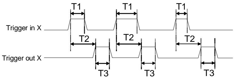
Trigger Control Timing Chart
![Trigger in X\nT1\nT1\nT1\nT2\nT2\nT2\nT3\nT3\nT3\nTrigger out X](.pcie-gie62-50-11168-1000-004/13688d127e07b53792e254b048e31ac31a263546397a7c794b71965e9b69d751.jpg)

<table><tr><td>Symbol</td><td>Characteristic</td><td>Specification</td></tr><tr><td>T1</td><td>Trigger input pulse width</td><td>Minimum width is 0.1 msec</td></tr><tr><td>T2</td><td>Trigger delay</td><td>0-1000 msec selectable(1 msec/step)</td></tr><tr><td>T3</td><td>Output trigger pulse width</td><td>0.1-50 msec selectable(0.1 msec/step)</td></tr></table>

![Trigger in X\nT1\nIgnore Trigger Input\nT1\nIgnore Trigger Input\nT2\nT2\nT3\nT3\nTrigger out X\nT4\nT4](.pcie-gie62-50-11168-1000-004/c1744b0d4aeae28961a76ff37c8f0131c27c4fb5f5a39d3942bdbb1e402bced3.jpg)

T4(Trigger counter busy time)=T2+T3;
If signal is on Trigger input channel during trigger
counter busy time,it will be ignored.

# 3 Installation Guide

# 3.1 Hardware Installation

Use the following steps to install the GIE62+ series board on the PCI express bus:

1. Remove the computer cover using the instructions from the computer manual.
2. Check that there is an empty PCI express slot. If there is not an empty slot, remove a PCI express board from the computer to make room for the GIE62+ board and take note of the chosen slot number.
3. Remove the blank metal plate located at the back of the selected slot (if any). Keep the removed screw to fasten the GIE62+ board after installation.
4. Carefully position the GIE62+ in the selected PCI express slot. If using a tower computer, align the board with the board slots.
5. Press the board firmly, but carefully into the connector.
6. Anchor the board by replacing the screw.
7. Plug in the cable to the PoE power connector (CN3).
8. Connect device via a Gigabit Ethernet connector.
9. Turn on the computer.

Note: The GIE62+ can be installed in a PCI Express x4, x8, and x16 slot.

# 3.2 Driver Installation

This is a two-part driver installation which includes installation of the Intel network connections driver and installation of the GIE62+ driver. The former is used for network connections between GIE62+ cards and PoE or Non-PoE GigE Vision cameras; the later is used for GIE62+ DIO and trigger functions.

1. Double Click GIE62+\_XP32.exe (for 2K/XP) or GIE62+\_Vista32.exe (for Vista) to start driver installation of the Intel network chipsets according to your operating system, and the Intel network connections driver installation will begin first.

![InstallShield Wizard\nPreparing to Install...\nGiE62+ Setup is preparing the InstallShield Wizard, which\nwill guide you through the program setup process. Please\nwait.\nExtracting: GiE62+.msi\nCancel](.pcie-gie62-50-11168-1000-004/d601c74472ae2d3fbf5d63a72204e3eb47d8d19834fa03d39b8ff919faac6679.jpg)

![Intel(R) Network Connections - InstallShield Wizard\nWelcome to the InstallShield Wizard for\nIntel(R) Network Connections\nIntel(R) Network Connections Setup is preparing the\nInstallShield Wizard which will guide you through the program\nsetup process. Please wait.\nInstallShield\n( Back	Next )	Cancel](.pcie-gie62-50-11168-1000-004/53614467b745d0caa9ed3cdee9ee12f4af99e489c5af6f724b3f95daf7f6fa16.jpg)

2. Select "I accept the terms in the license agreement" and click “Next” to continue driver installation.

![Intel(R) Network Connections - InstallShield Wizard\nLicense Agreement\nPlease read the following license agreement carefully.\nintel®\nINTEL SOFTWARE LICENSE AGREEMENT (Final, License)\nIMPORTANT - READ BEFORE COPYING, INSTALLING OR USING.\nDo not use or load this software and any associated materials (collectively, the 'Software') until you have carefully read the following terms and conditions. By loading or using the Software, you agree to the terms of this Agreement. If you do not wish to so agree, do not install or use the Software.\nLICENSES: Please Note:\nI accept the terms in the license agreement.\nI do not accept the terms in the license agreement\nPrint\n( Back	Next )	Cancel](.pcie-gie62-50-11168-1000-004/75621a18a25659c3a49c81c55fade4c443c2c9f360b61229faede7c2324aa645.jpg)

![Intel(R) Network Connections\nSetup Options\nSelect the program features you want installed.\nInstall:\n✓ Drivers\n✓ Intel(R) PROSet for Windows* Device Manager\n✓ Advanced Network Services\n□ Intel(R) Network Connections SNMP Agent\nFeature Description\n( Back	Next )	Cancel](.pcie-gie62-50-11168-1000-004/be44f50e27cdd706f6301388f3999272502c7b415860ea8d3ed6ec24363e4be5.jpg)

# 3. Click “Install” to start installing.

![Intel(R) Network Connections - InstallShield Wizard\nReady to Install the Program\nThe wizard is ready to begin installation.\nClick Install to begin the installation.\nIf you want to review or change any of your installation settings, click Back. Click Cancel to exit the wizard.\nInstallShield\n( Back	Install	Cancel](.pcie-gie62-50-11168-1000-004/1f2188b760a65a187ccd0dd91e75b79d4774ec122458b050d5bdc0c4b2d61a27.jpg)

![Intel(R) Network Connections - InstallShield Wizard\nInstalling Intel(R) Network Connections\nThe program features you selected are being installed.\nPlease wait while the InstallShield Wizard installs Intel(R) Network\nConnections. This may take several minutes.\nStatus:\nInstallShield\n( Back	Next )	Cancel](.pcie-gie62-50-11168-1000-004/ae28b7e657aaab6612b080bbfbec25ac618b4eafc445270bf07739b6cc2eafe7.jpg)

4. Click “Finish” to complete Intel network connections driver installation.

![Intel(R) Network Connections - InstallShield Wizard\nInstallShield Wizard Completed\nintel®\nTo access new features, open Device Manager, and view the\nproperties of the network adapters.\nInstallShield\n( Back	Finish	Cancel](.pcie-gie62-50-11168-1000-004/fd8a00863ba2f41b1934ed5f5deed2bd4b6350357587cb55b98f8926fc7db7ba.jpg)

5. After completing the Intel network connections driver installation, the GIE62+ driver installation phase will begin.

![GiE62+ - InstallShield Wizard\nWelcome to the InstallShield Wizard for GiE62+\nThe InstallShield(R) Wizard will install GiE62+ on your computer. To continue, click Next.\nWARNING: This program is protected by copyright law and international treaties.\n( Back	Next )	Cancel](.pcie-gie62-50-11168-1000-004/38b26d037936d1f9075d53d88717c1a0e69bfea2f7b6292c9ab6ec6eada699ef.jpg)

# 6. Click “Next” to continue driver installation.

![GiE62+ - InstallShield Wizard\nReady to Install the Program\nThe wizard is ready to begin installation.\nClick Install to begin the installation.\nIf you want to review or change any of your installation settings, click Back. Click Cancel to exit the wizard.\nInstallShield\n( Back	Install	Cancel](.pcie-gie62-50-11168-1000-004/a9b9daeb053873bf9021cc8b4af3dbdc1c2858a58acc1742a5d5fba77d485104.jpg)

# 7. Click “Install” to start installing.

![GiE62+ - InstallShield Wizard\nInstalling GiE62+\nThe program features you selected are being installed.\nPlease wait while the InstallShield Wizard installs GiE62+. This may take\nseveral minutes.\nStatus:\nInstallShield\n( Back	Next )	Cancel](.pcie-gie62-50-11168-1000-004/ae195ac46388b3e9ca4c7bbc401306716c0c56ff7ca698f5942da0124b72a183.jpg)

# 8. Click “Finish” to complete GIE62+ driver installation.

![GiE62+ - InstallShield Wizard\nInstallShield Wizard Completed\nThe InstallShield Wizard has successfully installed GiE62+. Click\nFinish to exit the wizard.\n( Back	Finish	Cancel](.pcie-gie62-50-11168-1000-004/36ec787b9180a899942907321c05d3133ca051d22aa169a182f471fcdc734893.jpg)

9. To ensure the Intel network connections driver has been installed successfully, go to the “Device Manager” and check “Network adapters”. You should see the following two items:

 Intel(R) PRO/1000 PT Dual Port Server Adapter
 Intel(R) PRO/1000 PT Dual Port Server Adapter #2

![Computer Management\nFile  Action  View  Window  Help\nComputer Management\nSystem Tools\nEvent Viewer\nShared Folders\nLocal Users and\nPerformance Lo\nDevice Manager\nStorage\nRemovable Stor\nDisk Defragment\nDisk Managemer\nServices and Applica\nADLINK-TEF8J85C\nComputer\nDisk drives\nDisplay adapters\nDVD/CD-ROM drives\nFloppy disk controllers\nHuman Interface Devices\nIDE ATA/ATAPI controllers\nKeyboards\nMice and other pointing devices\nMonitors\nNetwork adapters\nIntel(R) PRO/1000 S Server Adapter\nIntel(R) PRO/1000 EB Network Connection with I/O Acceleration\nIntel(R) PRO/1000 EB Network Connection with I/O Acceleration #2\nIntel(R) PRO/1000 PT Dual Port Server Adapter\nIntel(R) PRO/1000 PT Dual Port Server Adapter #2\nOther devices\nSM Bus Controller\nPorts (COM & LPT)\nProcessors](.pcie-gie62-50-11168-1000-004/12aba57ae999d220dc6b5c85725e2520daf98945c758b010716e5efb974bd306.jpg)

# 4 Function Library

This chapter describes the API for GIE62+ cards. Please refer to the sample programs in the installation folder, and then use these functions to develop application programs in C#, Visual Basic.NET, Visual Basic, Visual C++, or C++ Builder.

Note: C# and Visual Basic.NET sample programs were developed with Visual Studio 2005.

# 4.1 Function List

<table><tr><td>Function name</td><td>Description</td></tr><tr><td colspan="2">System Functions</td></tr><tr><td>GiE62_Initialize</td><td>Load the driver of GIE62+ card. You must call this function before any other functions</td></tr><tr><td>GiE62_GetTotalDeviceNum</td><td>Get the number of GIE62+ cards in your system</td></tr><tr><td>GiE62_GetTotalDeviceID</td><td>Get the CardID(s) of all GIE62+ cards in your system</td></tr><tr><td>GiE62_OpenDevice</td><td>Open GIE62+ card and set it to the default status</td></tr><tr><td>GiE62_ResetDevice</td><td>Reset GIE62+ card to the default status</td></tr><tr><td>GiE62_GetFirmwareVersion</td><td>Get the firmware version of GIE62+ card</td></tr><tr><td colspan="2">DIO Functions</td></tr><tr><td>GiE62_SetDOStatus</td><td>Set general purpose digital output status</td></tr><tr><td>GiE62_GetDIStatus</td><td>Get general purpose digital input status</td></tr><tr><td colspan="2">Trigger Functions</td></tr><tr><td>GiE62_SetTriggerDelayTime</td><td>Set the delay time of output triggers</td></tr><tr><td>GiE62_SetTriggerOutWidth</td><td>Set the width of output triggers</td></tr><tr><td>GiE62_SetTriggerOutPolarity</td><td>Set the output polarity of output triggers</td></tr><tr><td>GiE62_SetTriggerInPolarity</td><td>Set the input polarity of output triggers</td></tr><tr><td>GiE62_GetTriggerDelayTime</td><td>Get the delay time of output triggers</td></tr><tr><td>GiE62_GetTriggerOutWidth</td><td>Get the width of output triggers</td></tr><tr><td>GiE62_GetTriggerOutPolarity</td><td>Get the output polarity of output triggers</td></tr><tr><td>GiE62_GetTriggerInPolarity</td><td>Get the input polarity of output triggers</td></tr></table>

# 4.2 Functions

# 4.2.1 GiE62\_Initialize

# Description

Load the driver of GIE62+ card. You must call this function before any other functions.

# Syntax

int GiE62\_Initialize();

# 4.2.2 GiE62\_GetTotalDeviceNum

# Description

Get the number of GIE62+ cards from the value returned by this function.

# Syntax

int GiE62\_GetTotalDeviceNum();

# 4.2.3 GiE62\_GetTotalDeviceID

# Description

Get the CardID(s) of each GIE62+ cards in your system.

# Syntax

int GiE62\_GetTotalDeviceID(int \*DeviceID);

# Parameters

DeviceID

[out] Pointer to a 32-bit integer array with four elements which stores the read out CardID(s). Please note that the array size cannot be less than 4, and each GIE62+ card must be assigned a different CardID by through the DIP switch on board. If the array size is more than 4, only the first 4 elements contain CardID(s) since GIE62+ supports 4 cards at most in a system.

# 4.2.4 GiE62\_OpenDevice

# Description

Open the GIE62+ card and set it to the default status.

# Syntax

int GiE62\_OpenDevice(int CardID);

# Parameters

CardID

[in] Card ID of GIE62+. The card ID could be 0, 1, 2 and 3. It is defined by the DIP switch on the board.

# 4.2.5 GiE62\_ResetDevice

# Description

Reset the GIE62+ card and set it to the default status.

# Syntax

int GiE62\_ResetDevice(int CardID);

# Parameters

CardID

[in] Card ID of GIE62+. The card ID could be 0, 1, 2 and 3. It is defined by the DIP switch on the board.

# 4.2.6 GiE62\_GetFirmwareVersion

# Description

Get the firmware version of the GIE62+ card.

# Syntax

int GiE62\_GetFirmwareVersion(int CardID, char

\*FirmwareVersion, int StringSize);

# Parameters

CardID

[in] Card ID of GIE62+. The card ID could be 0, 1, 2 and 3. It is defined by the DIP switch on the board.

FirmwareVersion

[out] Pointer to a character array which stores the read out firmware version.

StringSize

[in] Size of the character array that will be returned.

# 4.2.7 GiE62\_SetDOStatus

# Description

Set the general purpose digital output status.

# Syntax

int GiE62\_SetDOStatus(int CardID, int port, int status);

# Parameters

CardID

[in] Card ID of GIE62+. The card ID could be 0, 1, 2 and 3. It is defined by the DIP switch on the board.

port

[in] Port number of GIE62+. The port number could be 1 and 2.

status

[in] A 32-bit integer variable which represents the status of digital output.

 0: Low
 1: High

# 4.2.8 GiE62\_GetDIStatus

# Description

Get the general purpose digital input status.

# Syntax

int GiE62\_GetDIStatus(int CardID, int port, int \*status);

# Parameters

CardID

[in] Card ID of GIE62+. The card ID could be 0, 1, 2 and 3. It is defined by the DIP switch on the board.

port

[in] Port number of GIE62+. The port number could be 1 and 2.

status

[out] Pointer to a 32-bit integer variable which stores the read out digital input status.

 0: Low
 1: High

# 4.2.9 GiE62\_SetTriggerDelayTime

# Description

Set the delay time of output triggers.

# Syntax

int GiE62\_SetTriggerDelayTime(int CardID, int port, int DelayTime);

# Parameters

CardID

[in] Card ID of GIE62+. The card ID could be 0, 1, 2 and 3. It is defined by the DIP switch on the board.

port

[in] Port number of GIE62+. The port number could be 1 and 2.

DelayTime

[in] A 32-bit integer variable which specifies the delay time of output triggers. The unit of delay time is in milliseconds (ms).

The value should be 0 - 1000.

# 4.2.10 GiE62\_SetTriggerOutWidth

# Description

Set the width of output triggers.

# Syntax

int GiE62\_SetTriggerOutWidth(int CardID, int port, int width);

# Parameters

CardID

[in] Card ID of GIE62+. The card ID could be 0, 1, 2 and 3. It is defined by the DIP switch on the board.

port

[in] Port number of GIE62+. The port number could be 1 and 2.

width

[in] A 32-bit integer variable which specifies the width of output triggers. The unit of width is in 0.1 milliseconds (ms).

The value should be 0 - 500.

# 4.2.11 GiE62\_SetTriggerOutPolarity

# Description

Set the output polarity of output triggers.

# Syntax

int GiE62\_SetTriggerOutPolarity(int CardID, int port, int OutPolarity);

# Parameters

CardID

[in] Card ID of GIE62+. The card ID could be 0, 1, 2 and 3. It is defined by the DIP switch on the board.

port

[in] Port number of GIE62+. The port number could be 1 and 2.

OutPolarity

[in] A 32-bit integer variable which specifies the output polarity of output triggers.

The value should be 0 or 1.

 0: Negative

 1: Positive

# 4.2.12 GiE62\_SetTriggerInPolarity

# Description

Set the input polarity of output triggers.

# Syntax

int GiE62\_SetTriggerInPolarity(int CardID, int port, int InPolarity);

# Parameters

CardID

[in] Card ID of GIE62+. The card ID could be 0, 1, 2 and 3. It is defined by the DIP switch on the board.

port

[in] Port number of GIE62+. The port number could be 1 and 2.

InPolarity

[in] A 32-bit integer variable which specifies the input polarity of output triggers.

The value should be 0 or 1.

 0: Falling

 1: Rising

# 4.2.13 GiE62\_GetTriggerDelayTime

# Description

Get the delay time of output triggers.

# Syntax

int GiE62\_GetTriggerDelayTime(int CardID, int port, int \*DelayTime);

# Parameters

CardID

[in] Card ID of GIE62+. The card ID could be 0, 1, 2 and 3. It is defined by the DIP switch on the board.

port

[in] Port number of GIE62+. The port number could be 1 and 2.

DelayTime

[out] Pointer to a 32-bit integer variable which stores the read out delay time of output triggers. The unit of delay time is in milliseconds (ms).

# 4.2.14 GiE62\_GetTriggerOutWidth

# Description

Obtain the width of output triggers.

# Syntax

int GiE62\_GetTriggerOutWidth(int CardID, int port, int \*width);

# Parameters

CardID

[in] Card ID of GIE62+. The card ID could be 0, 1, 2 and 3. It is defined by the DIP switch on the board.

port

[in] Port number of GIE62+. The port number could be 1 and 2.

width

[out] Pointer to a 32-bit integer variable which stores the read out width of output triggers. The unit of width is in 0.1 milliseconds (ms).

# 4.2.15 GiE62\_GetTriggerOutPolarity

# Description

Get the output polarity of output triggers.

# Syntax

int GiE62\_GetTriggerOutPolarity(int CardID, int port, int \*OutPolarity);

# Parameters

CardID

[in] Card ID of GIE62+. The card ID could be 0, 1, 2 and 3. It is defined by the DIP switch on the board.

port

[in] Port number of GIE62+. The port number could be 1 and 2.

polarity

[out] Pointer to a 32-bit integer variable which stores the read out output polarity of output triggers.

 0: Negative

 1: Positive

# 4.2.16 GiE62\_GetTriggerInPolarity

# Description

Get the input polarity of output triggers.

# Syntax

int GiE62\_GetTriggerInPolarity(int CardID, int port, int \*InPolarity);

# Parameters

CardID

[in] Card ID of GIE62+. The card ID could be 0, 1, 2 and 3. It is defined by the DIP switch on the board.

port

[in] Port number of GIE62+. The port number could be 1 and 2.

InPolarity

[out] Pointer to a 32-bit integer variable which stores the read out input polarity of output triggers.

 0: Falling
 1: Rising

# 4.3 Error Codes

<table><tr><td>Error Code</td><td>Meaning</td></tr><tr><td>0</td><td>ERROR_NoError</td></tr><tr><td>-1</td><td>ERROR_Invalid_CardID</td></tr><tr><td>-2</td><td>ERROR_Invalid_PortNo</td></tr><tr><td>-3</td><td>ERROR_DeviceNotOpened</td></tr><tr><td>-4</td><td>ERROR_DeviceAlreadyOpened</td></tr><tr><td>-5</td><td>ERROR_ParameterExceedLimit</td></tr><tr><td>-6</td><td>ERROR_DeviceCannotAccess</td></tr></table>

Table 4-1: Error Codes
[🔗 Link to the original document](.pcie-gie62-50-11168-1000-004/pcie-gie62-50-11168-1000-004.pdf)
