# PCIe-PXle-8638 Series

ADLINK PXIe Extension Kit

User's Manual

![Electronic hardware components including a network card and Ethernet card with green connectors (no visible text or symbols)](.pcie-pxie-8638-50-17050-1010/9ac71ac66b9c339f0d701a116470eeec490300b4503149b8788e9c73a47dcc85.jpg)

Manual Rev.: 2.1

Revision Date: Dec. 19, 2020

Part No: 50-17050-1010

Revision History

<table><tr><td>Revision</td><td>Release Date</td><td>Description of Change(s)</td></tr><tr><td>2.0</td><td>2014-12-29</td><td>Initial release</td></tr><tr><td>2.1</td><td>2020-12-19</td><td>Added PXIe-8638D/P models.</td></tr></table>

# Preface

# Copyright © 2020 ADLINK Technology Inc.

This document contains proprietary information protected by copyright. All rights are reserved. No part of this manual may be reproduced by any mechanical, electronic, or other means in any form without prior written permission of the manufacturer.

# Disclaimer

The information in this document is subject to change without prior notice in order to improve reliability, design, and function and does not represent a commitment on the part of the manufacturer.

In no event will the manufacturer be liable for direct, indirect, special, incidental, or consequential damages arising out of the use or inability to use the product or documentation, even if advised of the possibility of such damages.

ADLINK is committed to fulfill its social responsibility to global environmental preservation through compliance with the European Union's Restriction of Hazardous Substances (RoHS) directive and Waste Electrical and Electronic Equipment (WEEE) directive. Environmental protection is a top priority for ADLINK. We have enforced measures to ensure that our products, manufacturing processes, components, and raw materials have as little impact on the environment as possible. When products are at their end of life, our customers are encouraged to dispose of them in accordance with the product disposal and/or recovery programs prescribed by their nation or company.

![Symbol of a trash bin with crossed lines indicating no waste or restriction (no text or labels)](.pcie-pxie-8638-50-17050-1010/12141dd6187e691082c3a9e8e98bc4e28330fffb0059cd16b2b0639e56069595.jpg)

Battery Labels (for products with battery)
![The image displays a row of four recycling symbols. From left to right: a crossed-out waste bin; a square with the recycling arrows and the text 'Li-ion' below; a circular logo with 'RECYCLE' at the top and '1.800.822.8837' at the bottom, enclosing a smaller recycling symbol with 'RBRC' and 'Li-ion' inside; and a square with an X made of arrows, accompanied by the text '廢電池請回收' below.](.pcie-pxie-8638-50-17050-1010/3ff9c8028c70621f01689e30c15ad2d6235a9b6d7ccda36a1139bd3969296068.jpg)

# California Proposition 65 Warning

![The image displays a standard warning symbol consisting of a yellow triangle with a thick black border. Centered inside the triangle is a large black exclamation point.](.pcie-pxie-8638-50-17050-1010/57fc4452c167a4a772e17d26fb32df3d74bc2994ccf78d42fe6db94f41e02877.jpg)

WARNING: This product can expose you to chemicals including acrylamide, arsenic, benzene, cadmium, Tris(1,3-dichloro-2-propyl)phosphate (TDCPP), 1,4-Dioxane, formaldehyde, lead, DEHP, styrene, DINP, BBP, PVC, and vinyl materials, which are known to the State of California to cause cancer, and acrylamide, benzene, cadmium, lead, mercury, phthalates, toluene, DEHP, DIDP, DnHP, DBP, BBP, PVC, and vinyl materials, which are known to the State of California to cause birth defects or other reproductive harm. For more information go to www.P65Warnings.ca.gov.

# Trademarks

Product names mentioned herein are used for identification purposes only and may be trademarks and/or registered trademarks of their respective companies.

# Conventions

Take note of the following conventions used throughout this manual to make sure that users perform certain tasks and instructions properly.

![The image displays a graphic icon of a white document with a folded top-right corner and faint horizontal lines running across the page. A large, bold red checkmark is superimposed diagonally over the document.](.pcie-pxie-8638-50-17050-1010/a24a5fbb9d5a24236d6e6ddb33c63253afbb8a1dc643e2badcf98dc3832006c9.jpg)
NOTE:

Additional information, aids, and tips that help users perform tasks.

![A yellow triangular warning sign with a black border containing a black exclamation mark in the center.](.pcie-pxie-8638-50-17050-1010/c3b17b99eb0daeb59da58f3280d9a39df2c0ed1b24eb9055904a787b5312c79f.jpg)
CAUTION:

Information to prevent minor physical injury, component damage, data loss, and/or program corruption when trying to complete a task.

![The image displays a red triangular warning sign with a white exclamation point centered inside it.](.pcie-pxie-8638-50-17050-1010/1ce79ee1f902ad5e5eb33354aa0566217f6635b289746444cd49dd05441b82cd.jpg)
WARNING:

Information to prevent serious physical injury, component damage, data loss, and/or program corruption when trying to complete a specific task.

# Table of Contents

# Preface...... iii

# List of Figures ...... vii

# List of Tables ix

# 1 Introduction ...... 1

1.1 Controlling a PXI Express System via PCI Express ...... 1
1.2 Specifications.... 2
1.3 Features.... 3
1.4 Ordering Options 4
1.5 Applications 4
1.6 PXI Platform Services Installation.... 5

# 2 Getting Started 7

2.1 PCIe-PXle-8638 Kit Package Contents 7
2.2 Installation Environment 7
2.3 Installing the PCIe-8638 on a Host Computer 8
2.4 PXIe-8638 Series to PXIe Chassis Installation.... 10

2.4.1 PXIe-8638/D to PXIe Chassis Installation 10
2.4.2 PXIe-8638P to PXIe Chassis Installation 11

2.5 Cabling the Host Computer to a PXI Chassis.... 12

2.6 Configuration Block Diagrams 14

2.6.1 PC to PXle Chassis 14
2.6.2 PC to PXIe Chassis (Star Topology) 15
2.6.3 PC to PXIe Chassis (Daisy Chain Topology) ..... 16
2.6.4 PXIe to PXIe Chassis Connection 17

2.7 Power On/Off Sequence 18

# 3 Hardware Information.... 19

3.1 PCIe-8638 Layout, Connectors and Jumpers.... 19
3.2 PXIe-8638(D/P) Layout, Connectors and Jumpers...... 20

# A Appendix: Troubleshooting (FAQ) 23

# Important Safety Instructions.... 27

# Getting Service 29

# List of Figures

Figure 2-1: PCIe-8638 to Host PC Installation....9

Figure 2-2: PXIe-8638(D) to PXI™ Chassis Installation Diagram.... 10

Figure 2-3: PXIe-8638D/P to PXI Chassis Installation Diagram ..... 11

Figure 2-4: PCIe x8 Cable Assembly 12

Figure 2-5: PC to PXIe Chassis 14

Figure 2-6: PC to PXIe Chassis Block Diagram....14

Figure 2-7: PC to PXIe Chassis (Star Topology) 15

Figure 2-8: PC to PXIe Block Diagram (Star Topology)....15

Figure 2-9: PC to PXIe Chassis (Daisy Chain Topology)......16

Figure 2-10: PC to PXIe Block Diagram (Daisy Chain Topology) ..... 16

Figure 2-11: PXIe to PXIe Chassis Connection .... 17

Figure 2-12: PXIe to PXIe Chassis Connection Block Diagram...... 17

Figure 3-1: PCIe-8638 Mechanical Layout.... 19

Figure 3-2: PXIe-8638 Mechanical Layout....20

Figure 3-3: PXIe-8638D Mechanical Layout 20

Figure 3-4: PXIe-8638P Mechanical Layout 21

Figure A-1: Bus Number Information Result....24

This page intentionally left blank.

# List of Tables

Table 1-1: Model Specifications....3
Table 1-2: PXIe-8638 Series Power Consumption .... 3
Table 1-3: Ordering Options 4
Table 2-1: PCIe-8638 to Host PC Installation Legend 9
Table 3-1: PCIe-8638 Mechanical Layout Legend....19
Table 3-2: PCIe-8638 Connectors, Switches, and LEDs....19
Table 3-3: PXIe-8638 Series Connectors and LEDs 21
Table A-1: PCI Bus Number Requirements 24

This page intentionally left blank.

# 1 Introduction

The PCIe-PXIe-8638 PCI Express to PXI Express extension kit provides control of PXI Express modules installed in a PXIe chassis using high bandwidth PCI Express technology. The extension kit provides up to 4GB/s bandwidth using PCIe x8 Gen2 signaling. With comprehensive hardware and software transparency, the extension kit enables fast and convenient detection of any PXI modules installed in the system, requiring no additional drivers or software.

The host PC may be separated from the PXI Express chassis by up to five meters using high-quality shielded twisted copper cables. The robust and reliable PCIe to PXIe Extension Kit is suited for test and measurement applications with high-density I/O requirements and can be used in hazardous industrial control and automation environments.

The dual port PXIe-8638D provides the capability of multi-chassis control in a daisy chain configuration with the upper port connected to a PCIe-8638 installed in a host PC, or PXIe-8638D/PXIe-8638P in a PXI Express chassis, and the lower port connected to another PXIe-8638 or PXIe-8638D in subsequent chassis.

The PXIe-8638P supports multi-chassis expansion in a daisy or star chain configuration. A PXIe-8638P in a peripheral slot can connect to another chassis with a PXIe-8638 or PXIe-8638D to establish multi-chassis control.

# 1.1 Controlling a PXI Express System via PCI Express

Based on PCI Express technology, the PCIe to PXIe Extension Kit provides bus extension capability through a high-speed differential signal interface.

The PCIe-PXle-8638 PCI Express-to-PXI Express expansion kit provides additional PXI instrument slots to the host computer by implementing PCI Express-based control of PXI modules. The technology consists of a PCIe-8638 host adapter installed in the host computer, a PCIe x8 cable, and a PXle-8638 remote controller with the 3U (Eurocard) expansion module. The PCIe-8638 comes with a PCI Express x8 interface and a PCIe x8 cable connector.

1.2 Specifications

<table><tr><td></td><td>PCIe-8638</td><td>PXle-8638</td><td>PXle-8638D</td><td>PXle-8638P</td></tr><tr><td>Format</td><td>Low Profile</td><td colspan="3">Standard Profile</td></tr><tr><td>Compliance</td><td>PCI Express Base Specifications Rev. 2.0</td><td colspan="3">PXI-5 PXI Express Hardware Specification Rev. 2.0</td></tr><tr><td>Dimensions</td><td>Low-profile PCI Express module 142(W) x 69(H) mm</td><td colspan="2">PXI Express system module: 175 mm (W) x 107 mm (H)</td><td>PXle Peripheral Module 175 mm (W) x 107 mm (H)</td></tr><tr><td>Up-Link Port</td><td>To Host PC PCIe: PCIe Gen2 x8</td><td colspan="2">External Port: PCIe Gen2 x8</td><td>To PXIe chassis backplane: PCIe Gen2 x8</td></tr><tr><td>Down-Link Port</td><td>External Port: PCIe Gen2 x8</td><td>To PXIe chassis backplane: PCIe Gen2 Four-link configuration: x4 x4 x4 x4 Two-link configuration: x8 x16</td><td>To PXIe chassis backplane: PCIe Gen2 Four-link configuration: x4 x4 x4 x4 Two-link configuration: x8 x16 External Port: PCIe Gen2 x8</td><td>External Port: PCIe Gen2 x8</td></tr><tr><td>PXI Express Link Capability</td><td>N/A</td><td colspan="3">Four-link configuration: x4 x4 x4 x4 Two-link configuration: x16 x8</td></tr><tr><td>Data Bandwidth (max)</td><td colspan="4">4GB/s (PCIe x8 Gen2)</td></tr><tr><td>Power Consumption</td><td>4W (typical) 8W (max.)</td><td colspan="3">Refer to Table 1.2</td></tr></table>

<table><tr><td></td><td>PCIe-8638</td><td>PXIe-8638</td><td>PXIe-8638D</td><td>PXIe-8638P</td></tr><tr><td>Cable Length</td><td colspan="4">Up to 5 meters for Gen2</td></tr><tr><td>Operating Temperature</td><td colspan="4">0°C to 55°C</td></tr><tr><td>Storage Temperature</td><td colspan="4">-20°C to 70°C</td></tr><tr><td>Relative Humidity</td><td colspan="4">10% to 90%, non-condensing</td></tr></table>

Table 1-1: Model Specifications

<table><tr><td>Power Rail</td><td>12 V</td><td>3.3 V</td></tr><tr><td>Typical Current</td><td>0.85 A</td><td>1.3 A</td></tr><tr><td>Maximum Current</td><td>1.7 A</td><td>2.6 A</td></tr></table>

Table 1-2: PXIe-8638 Series Power Consumption

![The image displays a yellow triangular warning sign with a black border. Inside the triangle is a large black exclamation point. Below the triangle, the text 'CAUTION:' is printed in black capital letters.](.pcie-pxie-8638-50-17050-1010/5fbd5d49e082c55324b91986812cd2d0014af2d85188ccaba3afa31b3f979014.jpg)

Insertion loss in sockets and accessory cable connectors may increase after frequent multiple insertions/removals, degrading signal integrity of high speed PCI Express transmission. For each PCIe-PXle-8638 socket or accessory cable connector, more than 200 connections/disconnections can impede functionality and performance.

# 1.3 Features

▶ PXI-5 PXI Express hardware specification Rev. 2.0
PCI Express® Base Specifications Rev. 2.0
▶ Maximum system throughput 4 GB/s
▶ PXI Express system slot link capability:

▶ Four-link configuration: x4 x4 x4 x4

▶ Two-link configuration: x16 x8

▶ Expansion up to 5m (expansion cables at 2 or 5m)
▶ Comprehensive hardware and software transparency

# 1.4 Ordering Options

<table><tr><td>Product</td><td>Description</td></tr><tr><td>PCIe-PXle-8638/2M</td><td>PXle remote controller kit. PCIe-8638, PXle-8638, and 2m cable.</td></tr><tr><td>PCIe-PXle-8638/5M</td><td>PXle remote controller kit. PCIe-8638, PXle-8638, and 5m cable.</td></tr><tr><td>PCIe-PXle-8638D/2M</td><td>PXle remote controller kit. PCIe-8638, PXle-8638D, and 2m cable.</td></tr><tr><td>PCIe-PXle-8638D/5M</td><td>PXle remote controller kit. PCIe-8638, PXle-8638D, and 5m cable.</td></tr><tr><td>PCIe-8638</td><td>PCIe x8 host adapter for PCIe-to-PXle cable extension.</td></tr><tr><td>PXle-8638</td><td>PXle remote controller for PCIe-to-PXle cable extension.</td></tr><tr><td>PXle-8638D</td><td>PXle remote controller for PCIe-to-PXle cable extension, dual ports.</td></tr><tr><td>PXle-8638P</td><td>PXle peripheral module for PCIe-to-PXle cable extension.</td></tr><tr><td>2m Cable for PCIe/PXle-8638 SAS 2*4 Cable Assembly</td><td>2m PCIe x8 cable</td></tr><tr><td>5m PCIe x8 Cable for PCIe/PXle-8638</td><td>5m PCIe x8 cable</td></tr></table>

Table 1-3: Ordering Options

# 1.5 Applications

These extension kits are suitable for:

▶ Electronics manufacturing testing
▶ High-density I/O systems
▶ Industrial automation and control
▶ Military and aerospace
▶ Testing systems for remote and/or harsh environments
▶ Video capture

# 1.6 PXI Platform Services Installation

It is recommended that ADLINK PXI Platform Services be downloaded and installed prior to operation. See the ADLINK PXI Platform Services User's Manual for more details.

This page intentionally left blank.

# 2 Getting Started

![The image displays a simple icon of a white document or piece of paper. It features a folded top-left corner and faint horizontal lines across the surface. A large, bold red checkmark is superimposed over the center of the document.](.pcie-pxie-8638-50-17050-1010/a42bfcdaa8bf62a68c1fa89570d32d0e15eab69478809dcb38fa772fc0371b66.jpg)
NOTE:

Diagrams and images of equipment are for reference only. The actual system appearance may vary.

# 2.1 PCIe-PXle-8638 Kit Package Contents

PCI-8638 (PCI Express x8 host adapter for extension kit)
▶ PXIe-8638 Series (PXI Express remote controller)
▶ PCI Express x8 cable assembly (2 or 5m)
▶ Quick Start Guide

![The image displays a white document icon with a folded top-right corner and faint gray horizontal lines. A large, bold red checkmark is superimposed over the center of the document.](.pcie-pxie-8638-50-17050-1010/430ca07884ca9c2b771e8f0e12d1dc9ae1c0d6481a85f95308f409f902e75bea.jpg)
NOTE:

If any of the items in the contents list are missing or damaged, contact your ADLINK dealer.

# 2.2 Installation Environment

Whenever unpacking and preparing to install any equipment described in this manual, refer to the Appendix B, Important Safety Instructions:.

Install equipment in well lit areas on flat, sturdy surfaces with access to basic tools such as flat and cross-head screwdrivers.

The PCIe to PXIe Extension Kit contains several electrostatic sensitive components that can be easily damaged by static electricity. For this reason, the modules and chassis should be handled on a grounded anti-static mat and the operator should wear an anti-static wristband during the unpacking and installation procedure.

Inspect the components for any damage. Improper shipping and handling may cause damage to the components. Be sure there is no damage to the components before continuing with the installation.

![A yellow triangular warning sign with a black border and a black exclamation point in the center. Below the triangle, the text 'CAUTION:' appears in black capital letters.](.pcie-pxie-8638-50-17050-1010/04edba0e9b73bba023b3348e58fb17622c61349f4006c5f9ae9bd7561578de79.jpg)

Do not apply power to damaged equipment.

# 2.3 Installing the PCIe-8638 on a Host Computer

1. Power-off the host computer.
2. Unscrew the housing of the host computer using a (cross-head or flat-head) screwdriver. Open the housing.
3. Locate the PCI Express $^{®}$ extension module (PCIe-8638) and remove it from its packaging. (Wear anti-static gloves and use an anti-static surface when handling the module).
4. Install the PCIe-8638 in an available x8 or x16 PCI Express slot in the host computer. Be sure to firmly attach the PCIe-8638's bracket to the backplane of the host PC.
5. Close the chassis and re-install the housing screws.
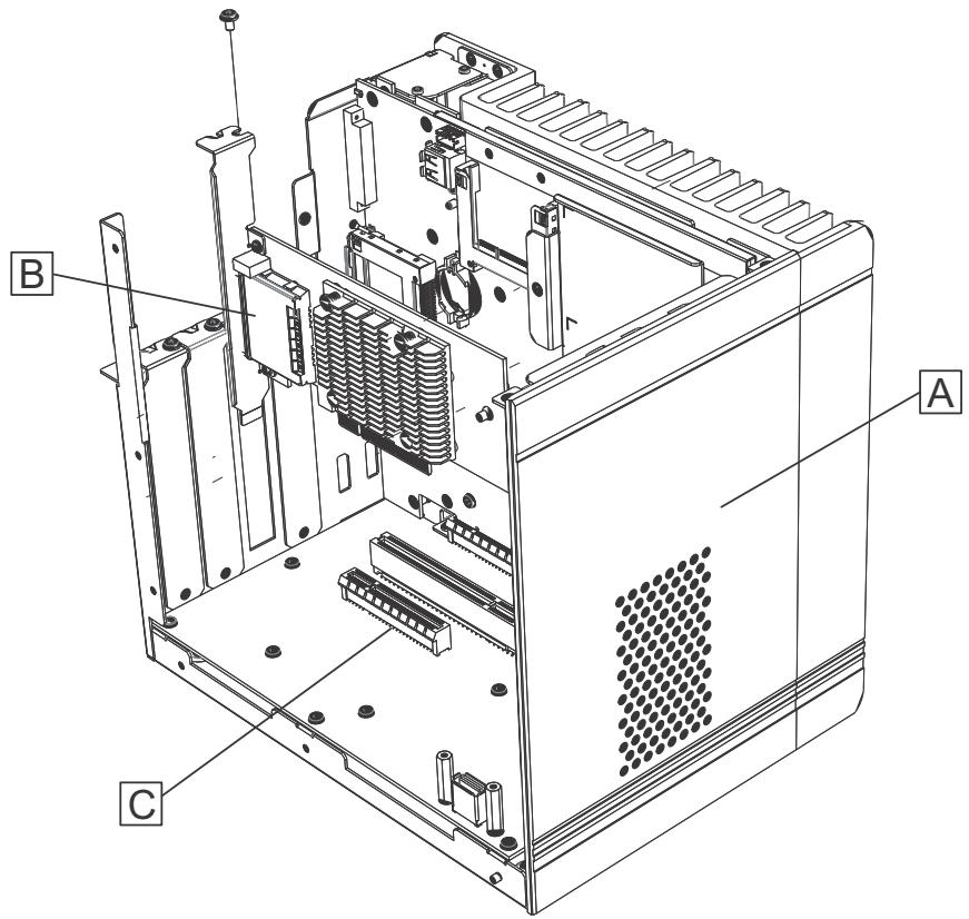
![Technical diagram of an electronic device with labeled components A, B, and C](.pcie-pxie-8638-50-17050-1010/fcd3c69fd2ea4ea281f34a8c188aacaff6cfc4f3b0d32ffe9370d957dae97c88.jpg)

Figure 2-1: PCIe-8638 to Host PC Installation

<table><tr><td>Item</td><td>Description</td></tr><tr><td>A</td><td>Industrial or desktop PC with PCI Express x8 slot</td></tr><tr><td>B</td><td>PCIe-8638 (PCI Express host module)</td></tr><tr><td>C</td><td>PCI Express x8 slot</td></tr></table>

Table 2-1: PCIe-8638 to Host PC Installation Legend

# 2.4 PXIe-8638 Series to PXIe Chassis Installation

# 2.4.1 PXIe-8638/D to PXIe Chassis Installation

1. Remove the cover panel of the system slot.
2. Locate the PXIe-8638/PXIe-8638D and remove it from its packaging. (Wear anti-static gloves and use an anti-static surface when handling the module).
3. Insert the PXIe-8638/PXIe-8638D into the system slot and tighten the bracket-retaining screws on the top and bottom of the panel to fasten the PXIe-8638/PXIe-8638D to the chassis.

![Technical line drawing of a server rack unit with mounting bracket and internal panel (no text or symbols)](.pcie-pxie-8638-50-17050-1010/06f46c657d0166472906caeb09207face1e4b49f6cd1078ddfc5d8aa7fa67742.jpg)

Figure 2-2: PXIe-8638(D) to PXI™ Chassis Installation Diagram

![The image displays a red triangular warning sign featuring a white exclamation point in the center. Beneath the triangle is a white rectangular box containing the word 'WARNING' in black, uppercase text.](.pcie-pxie-8638-50-17050-1010/dd30a8fa0e203d796526a8ecb2ec2045a2aa1c27e4eaf7e80fda2a7f3b034143.jpg)

The PXIe-8638/PXIe-8638D must be installed into the PXI $^{TM}$ system slot. Peripheral slots must not be used.

# 2.4.2 PXle-8638P to PXle Chassis Installation

1. Remove the cover panel of the peripheral slot assigned for connecting to an extension chassis based on application requirements.
2. Locate the PXIe-8638P and remove it from its packaging. (Wear anti-static gloves and use an anti-static surface when handling the module).
3. Insert the PXIe-8638P into the peripheral slot and tighten the bracket-retaining screws on the top and bottom of the panel to fasten the PXIe-8638P to the chassis.

![Technical line drawing of a server rack unit with mounting brackets and drive slots (no text or symbols)](.pcie-pxie-8638-50-17050-1010/42175a77c32b1fd93075c55e147664e66920712288d79b95f24392af070622f0.jpg)

Figure 2-3: PXIe-8638D/P to PXI Chassis Installation Diagram

![This image features a triangular warning sign. The triangle is dark red with a white border and contains a large white exclamation point in the center. Directly below the triangle, the word 'WARNING' is written in black capital letters.](.pcie-pxie-8638-50-17050-1010/10beef5cfc212bf819f590edd7dd55cdeba557e0bce820962f95a10d5508ac93.jpg)

The PXIe-8638P must be installed into the PXI peripheral slot, System slots may not be used.

# 2.5 Cabling the Host Computer to a PXI Chassis

Connect the PCIe cable assembly between the PCIe-8638, PXIe-8638, PXIe-8638D, and/or PXIe-8638P.

![The image displays a standard warning sign featuring a yellow triangle with a black border. Inside the triangle is a large black exclamation point. Below the triangle, the text 'CAUTION:' is printed in bold, black capital letters.](.pcie-pxie-8638-50-17050-1010/92d69d2c604529dcb89451ed8ad8e194501e50f67fd0f05966238c85186d28df.jpg)

Removing the PCIe cable assembly after the system is powered on may cause system errors or data loss. If the cable is unplugged improperly, reconnect it and reboot the host PC and PXI chassis.

![Coiled black cable with a green connector and metallic connector attached, placed on a plain white surface (no text or symbols visible)](.pcie-pxie-8638-50-17050-1010/f29bb34034566b3f286fbccb5d61868630f4dbf41b8105309848e85bb1588e4d.jpg)

Figure 2-4: PCIe x8 Cable Assembly

1. Connect the cable assembly to the external port on the bracket of the PCIe-8638 located in the host PC.
2. Connect the other end of the cable assembly to the external port of the PXIe-8638 or uplink port of the PXIe-8638D installed into the system slot of the PXI Express chassis.

3. In a multiple PXI Express chassis configuration, connect another cable assembly to the downlink port of the PXIe-8638D or external port of the PXIe-8638P installed into the first PXI Express chassis. Then, connect the other end of cable assembly to the external port of the PXIe-8638 or uplink port of the PXIe-8638D installed into the system slot of the next PXI Express chassis.

# 2.6 Configuration Block Diagrams

# 2.6.1 PC to PXle Chassis

![This diagram illustrates a connection between two systems:\n\n**Labeled Blocks:**\n*   On the left, inside a computer tower, is a block labeled **PCIe-8638**.\n*   On the right, inside a chassis unit, is a block labeled **PXIe-8638**.\n\n**Connections:**\n*   An orange arrow connects the two blocks. It originates from the **PXIe-8638** block and points towards the **PCIe-8638** block.](.pcie-pxie-8638-50-17050-1010/631a801ce58692fdeb0256938f690a16473c46f4a1def87417ba14979192a12a.jpg)

Figure 2-5: PC to PXle Chassis

![Based on the provided image, here is an accurate and concise description of the flowchart:\n\n**Labeled Blocks:**\n*   **Host PC:** A large blue square on the left side.\n*   **PCIe-8638:** A white box situated within the Host PC area. Inside this box is a smaller box labeled **PLX SWITCH**.\n*   **PXle-8638:** A white box to the right of the PCIe-8638 box. Inside this box is a smaller box labeled **PLX SWITCH**.\n*   **Remote PXle Chassis:** A large white rectangular container on the right side.\n*   **PXle Slot:** Three boxes located inside the Remote PXle Chassis container (one at the top, one in the middle, and one at the bottom).\n\n**Connections:**\n*   **Main Bus:** A thick, horizontal, double-headed orange arrow connects the left side (Host PC/PCIe-8638) to the right side (PXle-8638). It passes through both the PCIe-8638 and PXle-8638 boxes.\n*   **Interconnect Link:** Between the PCIe-8638 and PXle-8638 boxes, there are two vertical white rectangles with black outlines, representing a physical link (likely fiber optic).\n*   **Slot Connections:** Thin orange lines extend from the right side of the PXle-8638 box to connect to each of the three **PXle Slot** boxes.\n*   **Slot Hierarchy:** A vertical dashed line connects the middle **PXle Slot** box to the bottom **PXle Slot** box.](.pcie-pxie-8638-50-17050-1010/90b6604e5477c9d2929a22f5b464c121421e43fdc852d5e4970403715a7a836a.jpg)

Figure 2-6: PC to PXIe Chassis Block Diagram

# 2.6.2 PC to PXle Chassis (Star Topology)

![Based on the provided image, here is the accurate description of the flowchart:\n\n**Labeled Blocks:**\n*   **PC Tower:** Located on the far left, featuring a slot labeled **PCIe-8638**.\n*   **Central Chassis:** Located in the middle, containing three modules labeled **PXI-8638** (top), **PXI-863IP** (middle), and **PXI-863IP** (right).\n*   **Top-Right Chassis:** Located on the top right, labeled **PXI-8638**.\n*   **Bottom-Right Chassis:** Located on the bottom right, labeled **PXI-8638**.\n\n**Connections:**\n*   An orange line connects the PC tower (**PCIe-8638**) to the top module of the central chassis (**PXI-8638**).\n*   An orange line connects the rightmost module of the central chassis (**PXI-863IP**) to the top-right chassis (**PXI-8638**).\n*   An orange line connects the middle module of the central chassis (**PXI-863IP**) to the bottom-right chassis (**PXI-8638**).](.pcie-pxie-8638-50-17050-1010/6d4c97a7a956a5095e720c9ffb35b6c3fb2fb9aa1e4909e05095ab490006f4f9.jpg)

Figure 2-7: PC to PXle Chassis (Star Topology)

![Based on the provided flowchart, here is the description of the blocks and connections:\n\n**Blocks:**\n*   **Host PC**: A blue box containing a smaller white box labeled 'PCIe-8638' and 'PLX SWITCH'.\n*   **Central Remote PXIe Chassis**: Contains three stacked switches:\n    *   Top: 'PXIe-8638' and 'PLX SWITCH'.\n    *   Middle: 'PXIe-8638P' and 'PLX SWITCH'.\n    *   Bottom: 'PXIe-8638P' and 'PLX SWITCH'.\n*   **Top-Right Remote PXIe Chassis**: Contains 'PXIe-8638' and 'PLX SWITCH'.\n*   **Bottom-Right Remote PXIe Chassis**: Contains 'PXIe-8638' and 'PLX SWITCH'.\n*   **Slots**: Multiple boxes labeled 'PXIe Slot'.\n\n**Connections:**\n*   **Main Bus**: A thick orange line originates from the **Host PC**, enters the **PCIe-8638** block, and exits to the **PLX SWITCH**. It then connects to the **PLX SWITCH** inside the top **PXIe-8638** block of the central chassis.\n*   **Central Chain**: The thick orange line continues downward, connecting sequentially from the top **PLX SWITCH** to the middle **PXIe-8638P PLX SWITCH**, and then to the bottom **PXIe-8638P PLX SWITCH**.\n*   **Branching Connections**:\n    *   A line branches from the top **PLX SWITCH** (in the central chassis), goes right and up, connecting to the **PLX SWITCH** in the **Top-Right Remote PXIe Chassis**.\n    *   A line branches from the bottom **PLX SWITCH** (in the central chassis), goes down and right, connecting to the **PLX SWITCH** in the **Bottom-Right Remote PXIe Chassis**.\n*   **Slot Connections**:\n    *   In the **Central Remote PXIe Chassis**: The top switch connects to two 'PXIe Slot' boxes. The middle switch connects to one 'PXIe Slot'. The bottom switch connects to one 'PXIe Slot'. A dashed line labeled 'PXIe Slot' runs vertically between them.\n    *   In the **Top-Right** and **Bottom-Right** chassses: Each 'PLX SWITCH' connects to two 'PXIe Slot' boxes at the top and one at the bottom. A dashed line labeled 'PXIe Slot' runs vertically between them.](.pcie-pxie-8638-50-17050-1010/955f61710e821219bf5100753e919ff857566a3c5c62aefbcfdb00be78219514.jpg)

Figure 2-8: PC to PXIe Block Diagram (Star Topology)

# 2.6.3 PC to PXle Chassis (Daisy Chain Topology)

![The image displays a block diagram with four main components arranged horizontally from left to right:\n\n1.  **Computer Monitor:** Located on the far left.\n2.  **PC Tower:** Located next to the monitor. Inside the tower is a block labeled **PCIe-8638**.\n3.  **Middle Chassis:** Located in the center. Inside this chassis is a block labeled **PXle-8638D**.\n4.  **Right Chassis:** Located on the far right. Inside this chassis is a block labeled **PXle-8638**.\n\n**Connections:**\n*   An orange line originates from the **PCIe-8638** block in the PC tower, moves right, then up, and finally left, with an arrowhead pointing towards the **PXle-8638D** block in the middle chassis.\n*   Another orange line originates from the **PXle-8638** block in the right chassis, moves left, then down, and finally left, with an arrowhead pointing towards the middle chassis (specifically entering near the bottom right of the chassis).](.pcie-pxie-8638-50-17050-1010/3e16c3373882589f28a7e4e95f4cb73de717c6237f684364e7f2dfe9d1d7fd25.jpg)

Figure 2-9: PC to PXIe Chassis (Daisy Chain Topology)

![The diagram illustrates a daisy-chained configuration of PXIe chassis connected to a host computer.\n\n**Labeled Blocks:**\n*   **Host PC**: A large blue square on the far left.\n*   **PCIe-9638**: A white box inside the 'Host PC' area containing the text **PLX SWITCH**.\n*   **Remote PXIe Chassis**: A large vertical rectangle containing a switch and slots. This label appears twice, once for the middle group and once for the right group.\n*   **PXIe-9638**: A white box inside each 'Remote PXIe Chassis' containing the text **PLX SWITCH**.\n*   **PXIe Slot**: Small white boxes inside the chassis. There are three in the middle chassis and three in the rightmost chassis.\n\n**Connections:**\n*   **Host PC to Remote PXIe Chassis**: Two thick orange arrows indicate bidirectional communication between the **PCIe-9638** block in the Host PC and the **PXIe-9638** block in the first **Remote PXIe Chassis**.\n*   **Chassis Interconnection**: A thick orange line originates from the connector area of the first **Remote PXIe Chassis**, goes down, runs horizontally to the right, and enters the left side of the second **Remote PXIe Chassis**. Inside the second chassis, a thick orange arrow points left from the **PXIe-9638** block.\n*   **Slot Connections**: Thin orange lines connect the right side of the **PXIe-9638** block to the **PXIe Slot** boxes within their respective chassis.\n*   **Slot Interconnections**: Dashed black lines connect the middle and bottom **PXIe Slot** boxes in both chassis.](.pcie-pxie-8638-50-17050-1010/72f23549a08acb3368d4b430a87ca47d14beb85ab529562f0a19c32296a4cacf.jpg)

Figure 2-10: PC to PXle Block Diagram (Daisy Chain Topology)

# 2.6.4 PXIe to PXIe Chassis Connection

![The diagram displays two hardware chassis units. The left unit is labeled **'Controller'** at the top and features a module on its far right side labeled **'PXIe-8638P'**. The right unit features a module on its far left side labeled **'PXIe-8638'**. An orange line connects the **'PXIe-8638'** module to the **'PXIe-8638P'** module, with an arrowhead pointing towards the latter.](.pcie-pxie-8638-50-17050-1010/95c4334424b7ddcf03f92b2adc93575a2c2f05771b4611656b47580ad5c6f258.jpg)

Figure 2-11: PXle to PXle Chassis Connection

![Based on the provided flowchart, here is the accurate description of the labeled blocks and their connections:\n\n**Labeled Blocks:**\n*   **Remote PXIe Chassis** (appears twice, framing the left and right sections)\n*   **PXIe Slot** (appears three times within each chassis box, with dashed lines indicating additional slots)\n*   **PXIe-8638P** (located inside the bottom-left of the left chassis)\n*   **PLX SWITCH** (located inside the **PXIe-8638P** box)\n*   **PXIe-8638** (located inside the top-left of the right chassis)\n*   **PLX SWITCH** (located inside the **PXIe-8638** box)\n\n**Connections:**\n*   **Thin Orange Lines:** Within each 'Remote PXIe Chassis,' thin orange lines connect the individual 'PXIe Slot' boxes to the 'PLX SWITCH' module contained within the chassis.\n*   **Thick Orange Line:** A thick orange line connects the 'PLX SWITCH' in the 'PXIe-8638P' box to the 'PLX SWITCH' in the 'PXIe-8638' box.\n    *   Inside the 'PLX SWITCH' box on the left (**PXIe-8638P**), there is an arrow pointing to the **right**.\n    *   Inside the 'PLX SWITCH' box on the right (**PXIe-8638**), there is an arrow pointing to the **left**.](.pcie-pxie-8638-50-17050-1010/977bf2781135d8d0f7ee08c018184b684f5bf29e3e2d652a9bbb7d38b95a23d9.jpg)

Figure 2-12: PXle to PXle Chassis Connection Block Diagram

# 2.7 Power On/Off Sequence

To power-on the PCIe to PXIe Extension Kit:

1. Ensure that the extension cable is properly connected to the host PC and PXIe chassis.
2. In a single chassis configuraiton, power on the PXIe chassis. In a multiple chassis configuration, power on the most subordinate chassis in the configuration first, then power on the uplink chassis. Continue until all chassis are powered on.
3. When the status LEDs of the PXI Express chassis and all installed modules indicate ready, power on the host PC.

![A yellow triangular warning sign featuring a black exclamation point, with the word 'CAUTION:' printed below in black capital letters.](.pcie-pxie-8638-50-17050-1010/ada4fbaac46b78003d8560a696ec95b91167b20696c78a51528aeaad85933995.jpg)

DO NOT remove the cable after the system and PXIe chassis are powered on. Disconnecting the cable while the system is running may cause unpredictable system errors and/or a system crash.

As the PCIe to PXIe Extension Kit is equipped with a standard PCIe switch, the BIOS will identify each device behind the switch and assign resources to each during startup. Thus the PXI Express chassis must be powered up in order to acquire appropriate resources from the BIOS.

To power down the PCIe to PXIe Extension Kit:

1. Power down the host PC.
2. Power down the PXIe chassis.

![The image displays a standard warning sign featuring a yellow triangle with a black exclamation point in the center. Below the triangle, the text 'CAUTION:' is printed in black capital letters.](.pcie-pxie-8638-50-17050-1010/5ad3a04b5a319383c37a8359d058a4d6bdbdeb82e880a78c5f59fe141f1f3b6d.jpg)

DO NOT power down the PXIe chassis until the host PC is powered off. If the PXIe chassis is powered off while the host PC is on, the host PC may hang or crash.

# 3 Hardware Information

# 3.1 PCIe-8638 Layout, Connectors and Jumpers

![STATUS\nHOST\nPCs\nA\nC\nB](.pcie-pxie-8638-50-17050-1010/b8faa31105d24aa7b137aee949c1558cada06e583c7e5ec74cdc2c62d13f701e.jpg)

Figure 3-1: PCIe-8638 Mechanical Layout

<table><tr><td>A</td><td>PCIe x8 external downlink port</td></tr><tr><td>B</td><td>PCIe x8 edge finger</td></tr><tr><td>C</td><td>SW1</td></tr></table>

Table 3-1: PCIe-8638 Mechanical Layout Legend

<table><tr><td>Connector/Switch/LED</td><td>Description</td></tr><tr><td rowspan="3">STATUS LED</td><td>Off: No power</td></tr><tr><td>Orange: Power OK</td></tr><tr><td>Green: Device connected to downlink port is present</td></tr><tr><td rowspan="3">HOST(Link status between PCIe-8638 and PXIe-8638)</td><td>Off: No link</td></tr><tr><td>0.5Hz Blinking: Link in PCIe Gen1 signaling</td></tr><tr><td>1Hz Blinking: Link in PCIe Gen2 signaling</td></tr><tr><td>SW1</td><td>Default settings are:ON: Pin 3OFF: Pins 1,2,4</td></tr></table>

Table 3-2: PCIe-8638 Connectors, Switches, and LEDs

# 3.2 PXle-8638(D/P) Layout, Connectors and Jumpers

![ADLINK\nPLs-0438\nRemote\nCN5\nADLINK\nTECHNOLOGY INC.](.pcie-pxie-8638-50-17050-1010/fe66fddfbd7c76ffeb69fb1e0103b09c7415787d6a990c202b382cd757ba0de3.jpg)

Figure 3-2: PXIe-8638 Mechanical Layout

![ADLINK\nPX1e-8438D\nRemote\nController\nCN5\nCN6\nADLINK\nTECHNOLOGY INC.](.pcie-pxie-8638-50-17050-1010/06cde85214a69a9983cf63234d1703f3ca1374ea4090dd0bf021ffe03ce964cd.jpg)

Figure 3-3: PXIe-8638D Mechanical Layout

![PCI-4632P\nPCI Cable Interface\nCN6\nADLINK\nTECHNOLOGY INC.](.pcie-pxie-8638-50-17050-1010/e4ac649956b17676df117108bba90134e9ceffe3ddfb5e396b79e9feec1dc44c.jpg)

Figure 3-4: PXIe-8638P Mechanical Layout

<table><tr><td>Connector/Jumper/LED</td><td>Description</td></tr><tr><td>CN5</td><td>PCIe x8 external uplink port</td></tr><tr><td>CN6</td><td>PXle x8 external downlink port</td></tr><tr><td rowspan="3">PWR/PRSNT LED</td><td>Off: No power</td></tr><tr><td>Orange: Power OK</td></tr><tr><td>Green: Device connected to uplink/downlink port is present</td></tr><tr><td rowspan="3">LINK LED(Link status between PCIe-8638 and PXIe-8638 Series)</td><td>Off: No link</td></tr><tr><td>0.5Hz Blinking: Link in PCIe Gen1 signaling</td></tr><tr><td>1Hz Blinking: Link in PCIe Gen2 signaling</td></tr></table>

Table 3-3: PXle-8638 Series Connectors and LEDs

This page intentionally left blank.

# Appendix A Troubleshooting (FAQ)

This chapter describes frequently asked questions to assist in solving problems that may be encountered.

Question: What is the maximum extension length of the PCIe-PXle-8638?

Answer: ADLINK provides cable accessories for the PCIe-PX1e-8638 in 2 and 5 meter lengths, with a maximum cable length between systems at 5 meters.

Question: When using the PCIe-PXle-8638, are there any additional drivers or software required to install?

Answer: Yes, ADLINK PXI Platform Services supports the -8638/PXIe-8638D including SMBus controller drivers and PXI software framework.

ADLINK PXI Platform Services can be downloaded from the PCIe-PXIe-8638 product page on the ADLINK website.

Question: Which link configuration of the PXI Express system slot does the PCIe-PXle-8638 support, 4- or 2-link? How are the associated settings configured?

Answer: The PCIe-PXle-8638 acts as a generic PXI Express system controller that supports both 4-link and 2-link PXI Express system slots. It detects the backplane and configures automatically without any settings required.

Question: Are there any compatibility concerns with the PCIe-PXle-8638? How can a host PC be selected that will be most compatible with the PCIe-PXle-8638? How many chassis can be connected together via PCIe-PXle-8638?

Answer: Limited PCI bus availability is the major concern with compatibility. Available PCI bus numbers assigned by the system BIOS may exceed PCI bus numbers required by the

PCIe-PXIe-8638 and PXI Express chassis. If PCI bus numbers are occupied, the system may not boot correctly, or devices will not be detected.

Theoretically, PC systems implementing PCI Express can support up to 256 bus numbers. However, the maximum PCI bus numbers of many PC systems are frequently limited by the system BIOS based on the system design or architecture. Conversely, the PXI Express chassis consumes many PCI bus numbers. Each PXI Express peripheral slot reserves a PCI bus number, and PCI Express switches on a PXI Express chassis also occupy several PCI bus numbers. Some peripheral modules may also consume PCI bus numbers. PCI bus number requirements for ADLINK PXI Express chassis are as shown.

<table><tr><td>Model</td><td>PCI Bus Number Requirement</td></tr><tr><td>PCIe-PXle-8638 + PXES-2590</td><td>27</td></tr><tr><td>PCIe-PXle-8638 + PXES-2780</td><td>44</td></tr></table>

Table A-1: PCI Bus Number Requirements

Third party utilities like System Information Viewer (http://rh-software.com/) are able to check available PCI bus numbers in the system BIOS (Run SIV>>PCI Bus>>ACPI Buses), as shown.

![(ACPI Buses) (- SIV64X - System Information Viewer V4.48\nSIV64X - ACPI PCI Buses on \\XUANGLEE-NB - Windows 8.0 x64 Media Center Professional V6.02 Build 9200\nPCI Root Bus Physical Device Total Bus Range Free Bus Range PCIe Lanes Max Payload ACPI _BBN _CRS _DSM\n0 - 00 - 0 \Device\0000002b 64 0 -) 63 59 5 -) 63 PC10 ✓ 20 ✓ 514 □ DSM\nOverall 64 0 -) 63 59 PCIEXBAR 0000F8000000\nACPI MCFG 60 MMIO (PCIEXBAR) # Bus Range TOSHIIBA PORTEGE R930\n0000F8000000 0 0 -) 63](.pcie-pxie-8638-50-17050-1010/c8c3140708facc12d19a4d42d1af594efaf75980acb21ed565a6a67414b1d210.jpg)

Figure A-1: Bus Number Information Result

Question: One or more modules in the PXI Express chassis connected via PCIe-PXIe-8638 are missing from Windows Device Manager. What is the best solution for this or other compatibility problems (like no boot)?

Answer: Due to flexibility and the variety of systems with PCI Express expansion, most compatibility issues are related to abnormal device detection or resource assignment by the system BIOS. The following suggestions may help solve frequently encountered issues.

▶ Check that the PCIe-PXle-8638 and cable are properly installed.
▶ Check any abnormal LED status on the PCIe-PXle-8638. (See “PCIe-8638 Layout, Connectors and Jumpers” on page 19.)
▶ Check that the PCIe-PXle-8638 cables are not broken, bent, or have dirty/broken connectors.
▶ Make sure there are sufficient PXI Express bus numbers available.
▶ Occasionally updated BIOS system fixes cause resource limitation issues.
▶ Try different installation sequences of modules in PXI Express chassis.
▶ Try a different PCI Express slot or different host PC (different system BIOS).
▶ Remove some modules to free resources.

Question: Does the PCIe-PXle-8638 support Linux?

Answer: The PCIe-PXle-8638 is designed as a standard PCIe-to-PCIe bridge and should support most modern Linux kernels without additional driver requirements. Since the PXI Express software specification is based on a Windows environment, however, the PXI software framework and SMBus controller of the PCIe-PXle-8638 are not operable under Linux.

This page intentionally left blank.

# Important Safety Instructions

For user safety, please read and follow all instructions, Warnings, Cautions, and Notes marked in this manual and on the associated device before handling/operating the device, to avoid injury or damage.

▶ Read these safety instructions carefully.
- Keep the User’s Manual for future reference.
▶ Read the Specifications section of this manual for detailed information on the recommended operating environment.
The device can be operated at an ambient temperature of $55^{\circ}$ C.
- When installing/mounting or uninstalling/removing device, or when removal of a chassis cover is required for user servicing (See “Getting Started” on page 7.):
▷ Turn off power and unplug any power cords/cables.
▷ Reinstall all chassis covers before restoring power.

▶ To avoid electrical shock and/or damage to device:

▷ Keep device away from water or liquid sources.
▷ Keep device away from high heat or humidity.
▷ Keep device properly ventilated (do not block or cover ventilation openings).
▶ Always use recommended voltage and power source settings.
▶ Always install and operate device near an easily accessible electrical outlet.
▷ Secure the power cord (do not place any object on/over the power cord).
▶ Only install/attach and operate device on stable surfaces and/or recommended mountings.

▶ If the device will not be used for long periods of time, turn off and unplug it from its power source

▶ Never attempt to repair the device, which should only be serviced by qualified technical personnel using suitable tools

▶ A Lithium-type battery may be provided for uninterrupted backup or emergency power.

![The image displays a standard yellow triangular warning sign with a black border. Inside the triangle is a large black exclamation point. Below the triangle, the text 'CAUTION:' is printed in black capital letters.](.pcie-pxie-8638-50-17050-1010/14427f06d9bb41467339b6988fa5c2060f92ca7ae083af455867f1b88ff4e189.jpg)

Risk of explosion if battery is replaced with one of an incorrect type; please dispose of used batteries appropriately.

▶ The device must be serviced by authorized technicians when:

▷ The power cord or plug is damaged.
▷ Liquid has entered the device interior.
The device has been exposed to high humidity and/or moisture.
The device is not functioning or does not function according to the User's Manual.
The device has been dropped and/or damaged and/or shows obvious signs of breakage.

▶ Disconnect the power supply cord before loosening the thumbscrews and always fasten the thumbscrews with a screwdriver before starting the system up.

It is recommended that the device be installed only in a server room or computer room where access is:

▶ Restricted to qualified service personnel or users familiar with restrictions applied to the location, reasons therefor, and any precautions required.

▶ Only afforded by the use of a tool or lock and key, or other means of security, and controlled by the authority responsible for the location.

<table><tr><td>&lt;img src="images/31142552c1b0a41d821fa452fb979e256eaaca8f00abdcd0354a395d5d49d34c.jpg"/&gt;</td><td>BURN HAZARDTouching this surface could result in bodily injury.To reduce risk, allow the surface to cool before touching.</td></tr></table>

# Getting Service

Ask an Expert: http://askanexpert.adlinktech.com

# ADLINK Technology, Inc.

9F, No.166 Jian Yi Road, Zhonghe District

New Taipei City 235, Taiwan

Tel: +886-2-8226-5877

Fax: +886-2-8226-5717

Email: service@adlinktech.com

# Ampro ADLINK Technology, Inc.

5215 Hellyer Avenue, #110

San Jose, CA 95138, USA

Tel: +1-408-360-0200

Toll Free: +1-800-966-5200 (USA only)

Fax: +1-408-360-0222

Email: info@adlinktech.com

# ADLINK Technology (China) Co., Ltd.

300 Fang Chun Rd., Zhangjiang Hi-Tech Park

Pudong New Area, Shanghai, 201203 China

Tel: +86-21-5132-8988

Fax: +86-21-5132-3588

Email: market@adlinktech.com

# ADLINK Technology GmbH

Hans-Thoma-Straße 11

D-68163 Mannheim, Germany

Tel: +49-621-43214-0

Fax: +49-621 43214-30

Email: emea@adlinktech.com

Please visit the Contact page at www.adlinktech.com for information on how to contact the ADLINK regional office nearest you:
[🔗 Link to the original document](.pcie-pxie-8638-50-17050-1010/pcie-pxie-8638-50-17050-1010.pdf)
