# PXES-2596

# User’s Manual

3U 9-Slot Gen3 PXI Express Chassis

![Exterior view of an ADLINK network equipment unit (no visible text or symbols on the device body)](.pxes-2596-50m-70434-1000-05/29d9ea81cc467c865e93b236aa26e679116792ae83507bca5a1bf8db44c57aa2.jpg)

Manual Rev.: 0.5 Preliminary

Revision Date: January 26, 2026

Part Number: 50M-70434-1000

# Preface

# Copyright

Copyright 2026 ADLINK Technology, Inc. This document contains proprietary information protected by copyright. All rights are reserved. No part of this manual may be reproduced by any mechanical, electronic, or other means in any form without prior written permission of the manufacturer.

# Disclaimer

The information in this document is subject to change without prior notice in order to improve reliability, design, and function and does not represent a commitment on the part of the manufacturer. In no event will the manufacturer be liable for direct, indirect, special, incidental, or consequential damages arising out of the use or inability to use the product or documentation, even if advised of the possibility of such damages.

# Environmental Responsibility

ADLINK is committed to fulfill its social responsibility to global environmental preservation through compliance with the European Union’s Restriction of Hazardous Substances (RoHS) directive and Waste Electrical and Electronic Equipment (WEEE) directive. Environmental protection is a top priority for ADLINK. We have enforced measures to ensure that our products, manufacturing processes, components, and raw materials have as little impact on the environment as possible. When products are at their end of life, our customers are encouraged to dispose of them in accordance with the product disposal and/or recovery programs prescribed by their nation or company.

![Symbol of a trash bin crossed with no text or labels, accompanied by a blank rectangular block below (no text or symbols present)](.pxes-2596-50m-70434-1000-05/3e8a3e6ee5d53ecfe06d060b3aec013f1a3628b17d07975fa9916a9895a87739.jpg)

Battery Labels (for products with battery)

![Simple line drawing of a trash bin crossed out by two diagonal lines (no text or symbols)](.pxes-2596-50m-70434-1000-05/07c57c07c851a149332562db3f74734fdc4f889304f4a873a2c035fd4e5dcc3a.jpg)

![The image features a square outline containing the Mobius loop recycling symbol (three arrows forming a triangle). Directly below the square, the text '**Li-ion**' is displayed in bold, black, sans-serif font.](.pxes-2596-50m-70434-1000-05/61ebbe277f501c081b5ad9759a6bd99bea6e7860c45b953fa419f9d3bd6c1b1f.jpg)

![RECYCLE\nRBRC\nLi-ion\n1.800.822.8837](.pxes-2596-50m-70434-1000-05/a2ba1d57f0364551ff4d75441ab486517d6ae51c375d9d6d738943529cb9945f.jpg)

![廢電池請回收](.pxes-2596-50m-70434-1000-05/7e4c75b8f249182ba8645ff9dda01bac72898a6b049d9ecc334365910917b3b2.jpg)

# California Proposition 65 Warning

![A yellow triangular warning sign with a thick black border containing a black exclamation point in the center.](.pxes-2596-50m-70434-1000-05/68f6f97e78c5b7dd7d28c0241fee79dd41cad61e28fb625f7b072a6f0a104aa2.jpg)

WARNING: This product can expose you to chemicals including acrylamide, arsenic, benzene, cadmium, Tris(1,3-dichloro-2-propyl)phosphate (TDCPP), 1,4-Dioxane, formaldehyde, lead, DEHP, styrene, DINP, BBP, PVC, and vinyl materials, which are known to the State of California to cause cancer, and acrylamide, benzene, cadmium, lead, mercury, phthalates, toluene, DEHP, DIDP, DnHP,

DBP, BBP, PVC, and vinyl materials, which are known to the State of California to cause birth defects or other reproductive harm. For more information go to www.P65Warnings.ca.gov.

# Trademarks

Product names mentioned herein are used for identification purposes only and may be trademarks and/or registered trademarks of their respective companies.

Revision History

<table><tr><td>Revision</td><td>Description</td><td>Date</td></tr><tr><td>0.1</td><td>Preliminary release</td><td>2025-09-18</td></tr><tr><td>0.2</td><td>Specifications and fan descriptions updated</td><td>2025-11-07</td></tr><tr><td>0.3</td><td>Rack mount illustrations updated</td><td>2025-11-13</td></tr><tr><td>0.4</td><td>Specifications and safety instructions updated</td><td>2025-11-27</td></tr><tr><td>0.5</td><td>Backplane PCIe bus topology diagram updated</td><td>2026-01-26</td></tr></table>

# Table of Contents

# Preface...

# Table of Contents... .iv

# 1 Introduction....

1.1 Packing List ..
1.2 Features..
1.3 Specifications.. .2
1.4 Schematics . .4
1.5 Connectors, I/O, Controls. .5

# 2 Getting Started... .12

2.1 Power Supply Budget Considerations .. .12
2.2 Cooling Considerations . ..12
2.3 Cooling Configurations.. .12
2.4 Hardware Installation . .13
2.5 Rack Mounting...... .17
2.6 Powering Up the System. .17
2.7 PXES-2596 Software Resources .. ..18

# 3 System Management & Configuration............ ..19

3.1 ChassisWatch. ..19

# Safety Instructions... .22

# Getting Service...... .23

# 1 Introduction

The ADLINK PXES-2596 is a 9-slot PXI Express all hybrid chassis. It features 1 system slot and 8 hybrid slots, supporting CompactPCI, PXI, CompactPCI Express, and PXI Express modules for maximum flexibility. Built on a two-link PXI Express architecture with 16GB/s system bandwidth, all peripheral slots support PCIe Gen3 x4, providing up to 4GB/s per slot.

For expanded configurations, a 12-slot version called PXES-2596E is also available, featuring 1 system slot, 8 hybrid slots, and 3 additional PXI Express peripheral slots. This provides greater slot density and priceperformance ratio.

Additionally, both versions support single-board sales and features an ATX power design without a power board, simplifying integration and making it easier for single-board customer usage.

The chassis integrates a smart monitoring system that reports fan speed, system voltages, and internal temperature in real time. A 500W ATX power supply ensures stable operation for up to 50°C with superior cooling performance.

# 1.1 Packing List

PXES-2596 Chassis
• Power cords
Filler panel kit for unused/reserved slots including one 3-slot panel and eighteen 1-slot panels
• Optionally mount the chassis onto a server or similar rack using the Rack-Mount kit(G) (part number 91-95115-0010
PXES-2590).

# 1.2 Features

• PXI™-5 PXI Express hardware specification Rev.1.0 compliant
• 9-slot PXI Express chassis with one system slot and eight hybrid peripheral slots
Two-link PXI Express chassis
Up to 16 GB/s system bandwidth
Up to 4GB/s peripheral bandwidth for all slots
• $0 ^ { \circ } \mathsf { C }$ to $5 0 ^ { \circ } \mathsf { C }$ extended operating temperature range
Intelligent chassis managementSBC-FM-4U5C function module
Automatic fan speed control
Chassis status monitoring and reporting
SMA internal connectors for 10 MHz clock input/output
• Industrial-grade ATX power supply
• Power, temperature, and fan monitoring LEDs

# 1.3 Specifications

The PXES-2596 complies with the PXI™-5 Specification Rev.1.0 and accepts all modules compliant with the PXITM-5 and Compact PCI specification.

<table><tr><td colspan="4">Power Supply</td></tr><tr><td colspan="4"></td></tr><tr><td colspan="4">AC Input (*guaranteed by power supply design)</td></tr><tr><td>Input voltage range</td><td colspan="3">115 to 240 VAC</td></tr><tr><td>Input voltage frequency</td><td colspan="3">47 to 63 Hz</td></tr><tr><td colspan="4">Input current rating</td></tr><tr><td>115 VAC</td><td colspan="3">8 A</td></tr><tr><td>230 VAC</td><td colspan="3">4 A</td></tr><tr><td colspan="4">DC Output</td></tr><tr><td>Maximum 500W (including system controller)</td><td colspan="3">500 W</td></tr><tr><td>VDC</td><td>Maximum</td><td>Load Regulation</td><td>Maximum Ripple &amp; Noise</td></tr><tr><td>+5V</td><td>40 A</td><td>±5%</td><td>60 mV</td></tr><tr><td>+12V</td><td>32 A</td><td>±5%</td><td>120 mV</td></tr><tr><td>-12V</td><td>(Transferred by 12V)</td><td>±5%</td><td>120mV</td></tr><tr><td>+3.3V</td><td>30 A</td><td>±5%</td><td>60mV</td></tr><tr><td>5Vsb</td><td>2 A</td><td>±5%</td><td>60 mV</td></tr></table>

<table><tr><td colspan="2">10 MHz System Reference Clock (10 MHz REF)</td></tr><tr><td>Maximum clock skew between slots</td><td>300 ps</td></tr><tr><td>Built-in 10 MHz clock Accuracy</td><td>±25 ppm</td></tr><tr><td colspan="2">100 MHz System Reference Clock: PXle_CLK100</td></tr><tr><td>Maximum slot-to-slot skew</td><td>100 ps</td></tr><tr><td>Accuracy</td><td>±25 ppm</td></tr><tr><td colspan="2">10 MHz clock output/input (internal connector)</td></tr><tr><td>BNC Output amplitude (internal connector)</td><td>1 Vpk-pk ±20% square-wave into 50 Ω2 Vpk-pk unloaded</td></tr><tr><td>BNC Output impedance (internal connector)</td><td>50 Ω ±5 Ω</td></tr><tr><td>Frequency input requirement</td><td>10 MHz ±100 PPM</td></tr><tr><td>Input signal (10MHz REF In BNC)</td><td>100 mVPP to 5 VPP(square or sine)</td></tr><tr><td>Input impedance (10MHz REF In BNC)</td><td>50 Ω ±5 Ω</td></tr><tr><td>Input signal (PXI_CLK10_IN on fifth slot)</td><td>5 V or 3.3 V TTL signal</td></tr></table>

<table><tr><td colspan="2">Cooling</td></tr><tr><td>Fans</td><td>2 sets of 210.38 CFM fans</td></tr><tr><td>Per-slot cooling capacity</td><td>58 W (verified by 40°C chamber test)38 W (verified by 50°C chamber test)</td></tr><tr><td colspan="2">Physical</td></tr><tr><td>Slots</td><td>9 (1x system slot, 8x hybrid peripheral slots)12 (1x system slot, 8x hybrid peripheral slots, 3x peripheral slots)</td></tr><tr><td>Chassis Dimensions</td><td>302.16 (W) x 177.8 (H) x 457 (D) mm</td></tr><tr><td>Backplane Dimensions</td><td>287.88 mm (W) X 165.45 mm (H)</td></tr><tr><td>Chassis Weight</td><td>11 kg (24.3 lb)</td></tr></table>

<table><tr><td colspan="2">Environmental</td></tr><tr><td>Storage</td><td>Ambient temperature: -20 to 70°CRelative humidity: 10 to 90%, noncondensing</td></tr><tr><td>Operating</td><td>Ambient temperature: 0 to 50°CRelative humidity10 to 90%, noncondensing</td></tr><tr><td>Functional shock</td><td>30 G, half-sine, 11 ms pulse duration</td></tr><tr><td>Random Vibration</td><td>Operating: 5 to 500 Hz, 0.3Grms, 3 axesNonoperating: 5 to 500 Hz,2.46 Grms, 3 axes</td></tr><tr><td colspan="2">Certification</td></tr><tr><td>Safety</td><td>EN 61010-1EN 61010-2-201</td></tr><tr><td>Electromagnetic Compatibility</td><td>Emissions: EN 55011 Class A Immunity: EN 61326-1</td></tr><tr><td>CE Compliance</td><td>Meets essential requirements of applicable European Directives, as amended for CE Marking:Low-Voltage Directive (safety): 73/23/EEC Electromagnetic Compatibility Directive (EMC): 9/336/EEC</td></tr></table>

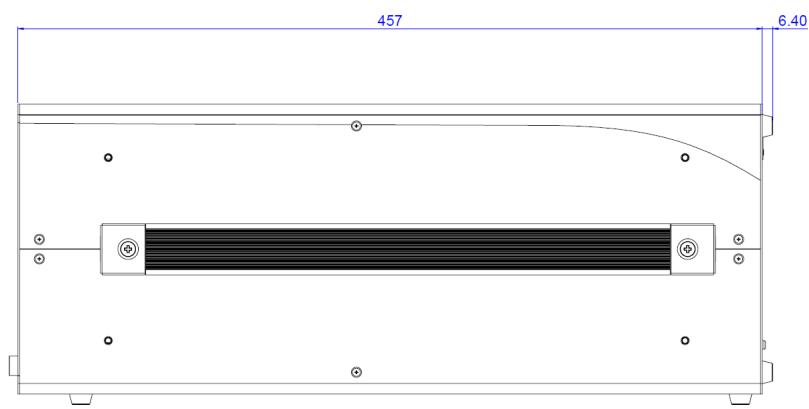
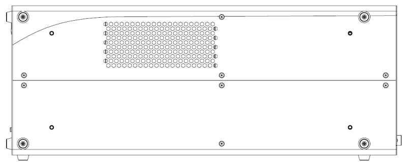
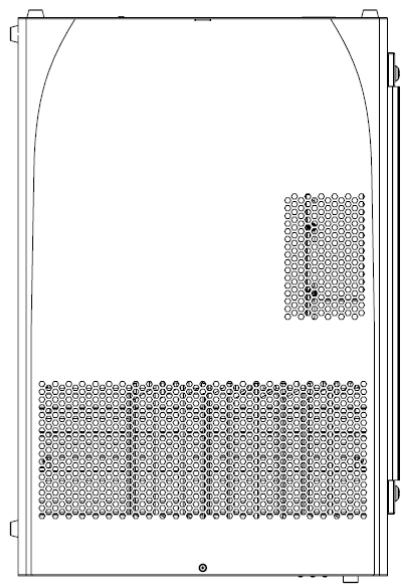
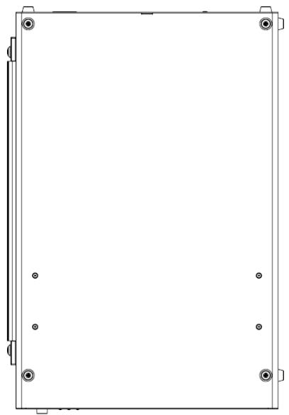
# 1.4 Schematics

Please note that all dimensions are shown in mm (milli- meters)
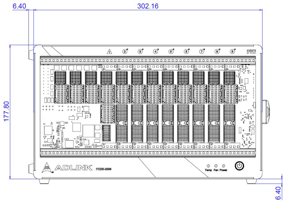
![6.40\n302.16\n177.80\nADLINK FXED-2006\nTemp Fan Power\n6.40](.pxes-2596-50m-70434-1000-05/8004e980359811c7e422c2411266a9a6e83431fcd0f88c99aaefc72be0883ab3.jpg)

![457\n6.40](.pxes-2596-50m-70434-1000-05/7a31ea9d3e66f1ce5f1f8c51a1d09ff2746cc49d98e41dca938f11707a8b8d9e.jpg)

Figure 1: Right Side View

![Technical line drawing of a device rear panel with grid pattern and mounting holes (no text or symbols)](.pxes-2596-50m-70434-1000-05/89df2b5d991bbc2f3f5bd0076298a3159e5eae446e9c3284381cf429bb3198ae.jpg)

Figure 2: Left Side View

![Diagram of a device casing with grid pattern and two vertical slots, no text or symbols present](.pxes-2596-50m-70434-1000-05/b8db44f8c7bbc006786a3ecae98d215b99a8713c4d628f1cd518f1c5710e066c.jpg)

Figure 3: Top View

![Pure technical line drawing of a rectangular frame with corner holes and mounting points (no text or symbols)](.pxes-2596-50m-70434-1000-05/5f08e777718d54e88be7fa809f55c628c23eb158832a8adc0add2b43bcc24e49.jpg)

Figure 4: Bottom View

# 1.5 Connectors, I/O, Controls

# 1.5.1 Front Panel
![ADLINK\nLeading EDGE COMPUTING PXES-2596\nTemp Fan Power\nB A](.pxes-2596-50m-70434-1000-05/877fc567758dda66e6733f1e860c8fb896811175a2f2ca423d2e708a01a79c14.jpg)

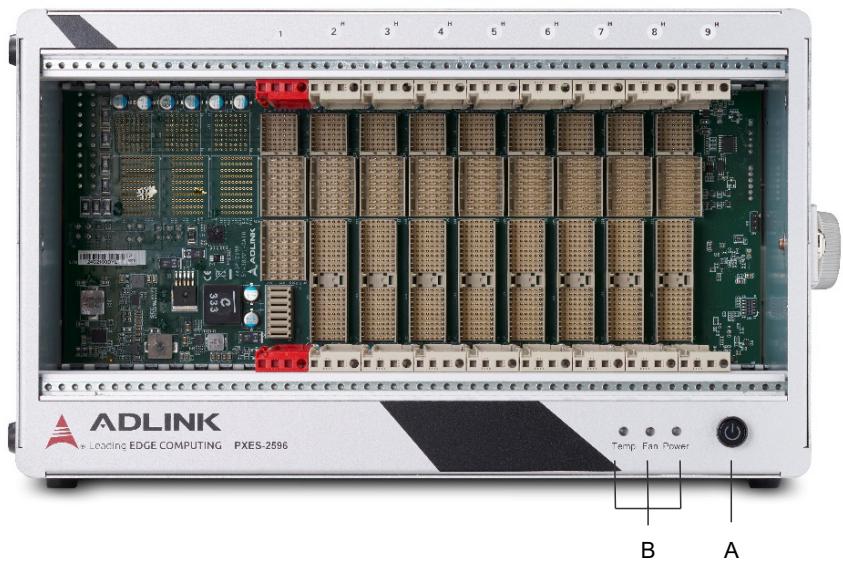
Figure 5: PXES-2590 Front Panel

<table><tr><td></td><td>Feature</td><td>Details</td></tr><tr><td>A</td><td>Power</td><td>Powers the chassis on/off (when INHIBIT on rear panel (not shown) is set to “DEF”)</td></tr><tr><td>B</td><td>Chassis Status</td><td>Temperature, Fan, and Power (L to R), functions as follows</td></tr></table>

<table><tr><td>Status</td><td>Power (Blue)</td><td>Fan (Green)</td><td>Temperature (Amber)</td></tr><tr><td>Off</td><td>Chassis is powered down.</td><td>Chassis is powered down.</td><td>Chassis is powered down or operating normal</td></tr><tr><td>On (Lit)</td><td>Chassis is powered on and operating normally.</td><td>Fans operating normally</td><td>N/A</td></tr><tr><td>Blinking</td><td>One or more power rails exceeds threshold settings (defaults are ±5% for 3.3V, 5V, +12V, and -12V, get voltage reading via chassis monitor utility).</td><td>One or more fans falls below threshold speed or no updates for a long period (configurable, default is 800RPM)</td><td>One or more temperature sensors exceeds threshold temperature. (configurable, default 70°C) TBD ES2 Thermal EVT</td></tr></table>

# 1.5.2 Rear Panel

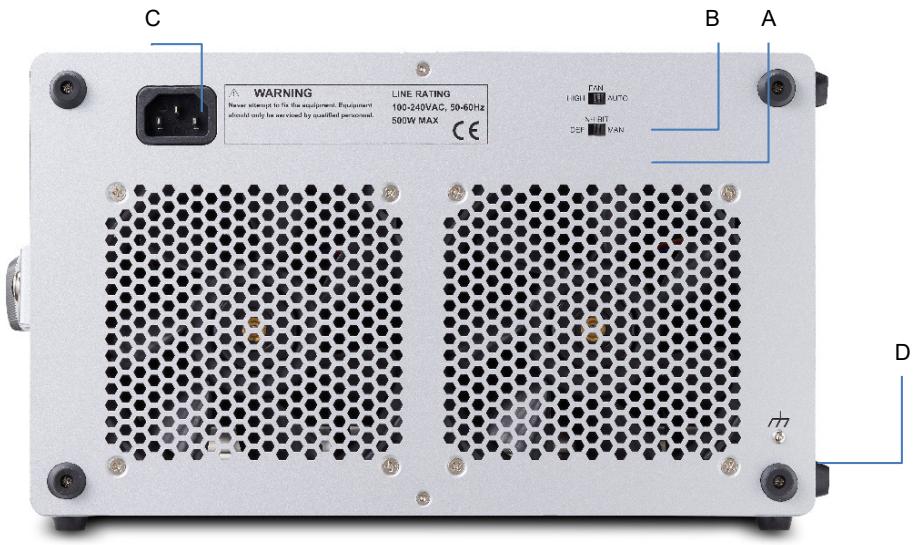
![C\nWARNING\nNever attempt to fix the equipment. Equipment\nalso only be revised by qualified personnel.\nLINE RATING\n100-240VAC, 50-60Hz\n500W MAX\nCE\nFAN\nHIGH OUTC\nMINI\nDEF VAN\nB\nA\nD](.pxes-2596-50m-70434-1000-05/f01ed1fc7d761ac8e3bd271283d9963985274cbf0ca220da28c8ae7273b0bc78.jpg)

Figure 6: PXES-2590 Rear Panel

<table><tr><td></td><td>Feature</td><td>Details</td></tr><tr><td>A</td><td>Inhibit Switch</td><td>In the DEF (default) position, the front panel power button turns the power supply on/off, and in the MAN (manual) position, the INHIBIT pin on the DB-9 connector turns the power supply on/off</td></tr><tr><td>B</td><td>Fan Switch</td><td>In the HIGH position, fans operate at maximum speed, and in AUTO, the fans run based on the monitored chassis temperature</td></tr><tr><td>C</td><td>Universal Power Inlet</td><td>Accepts C13 power outlet-equipped connection</td></tr><tr><td>D</td><td>Chassis Ground Lug</td><td>The ground wire can be crimped to the ground lug, using a crimp tool of the appropriate size, with the other end connected to ground</td></tr></table>

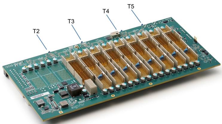
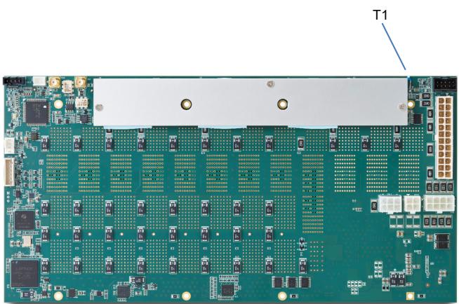
# 1.5.3 Backplane Thermal Sensors

![T2\nT3\nT4\nT5](.pxes-2596-50m-70434-1000-05/65b1333bd73e3ea886ce9ca5558216629b2bd0384e15fb32822516ec6c6a5844.jpg)

![Green printed circuit board with multiple integrated circuits and connectors (no visible text or symbols)](.pxes-2596-50m-70434-1000-05/cebf3081edb1907c68cb92f5e3636b5a603c26ddc3339bb1090015d75bfd0f7f.jpg)

# 1.5.4 PCI Express

Connector pin assignments of the PXI Express System Con- troller Slot, PXI Express Hybrid Peripheral Slots, and PXI Express Peripheral Slots comply with the default pin assignments as defined in PXI-5 PXI Express hardware specification Rev.1.1.

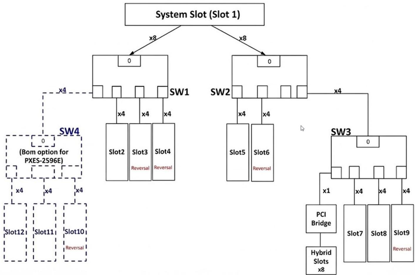
The PXES-2596 backplane provides a PCIe Gen3 switch fabric, allowing PCI express bus data streams between the system slot and all peripheral slots. The system slot supports up to PCIe 2-link x8 x8 Gen3 lanes, with all peripheral slots supporting up to PCIe x4 Gen3 links individually.
![**Top Level**\n*   **System Slot (Slot 1)**\n    *   Connected via **x8** to **SW1**\n    *   Connected via **x8** to **SW2**\n\n**Left Branch (SW1)**\n*   **SW1** (contains box labeled **0**)\n    *   Connected via **x4** to **Slot2**\n    *   Connected via **x4** to **Slot3** (contains text **Reversal**)\n    *   Connected via **x4** to **Slot4** (contains text **Reversal**)\n    *   Connected via dashed line **x4** to **SW4**\n        *   **SW4** (dashed box containing box labeled **0** and text **(Bom option for PXES-2596E)**)\n            *   Connected via dashed line **x4** to **Slot12**\n            *   Connected via dashed line **x4** to **Slot11**\n            *   Connected via dashed line **x4** to **Slot10** (contains text **Reversal**)\n\n**Right Branch (SW2)**\n*   **SW2** (contains box labeled **0**)\n    *   Connected via **x4** to **Slot5**\n    *   Connected via **x4** to **Slot6** (contains text **Reversal**)\n    *   Connected via **x4** to **SW3** (contains box labeled **0**)\n        *   **SW3**\n            *   Connected via **x1** to **PCI Bridge**\n                *   Connected to **Hybrid Slots x8**\n            *   Connected via **x4** to **Slot7**\n            *   Connected via **x4** to **Slot8**\n            *   Connected via **x4** to **Slot9** (contains text **Reversal**)](.pxes-2596-50m-70434-1000-05/9b6d694f7f6f3fe95aa1dd99d029100311153798a172054fc6b73bd81345cab0.jpg)

Figure 7: Backplane PCI Express Bus Topology

# PXI Express System Controller Slot

The System Controller slot is Slot 1 of the chassis as defined by the PXI specification. The PXES-2596 chassis can accommodate a PXI Express system controller that occupies width up to 4 slots. As defined in the PXI specification, three controller expansion slots allow the controller to expand to the left to pre-vent the controller from using up peripheral slots.

# PXI Express Hybrid Peripheral Slots

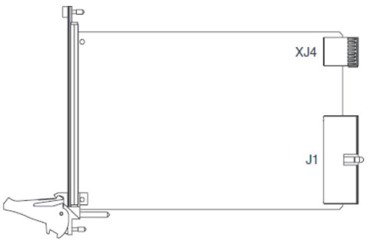
8 PXI Express hybrid peripheral slots are provided in the PXES-2596, all connected with PCIe x4 Gen3 lanes. Each can accommodate a 3U PXI Express CompactPCI Express / hybrid slot compatible PXI-1 Compact- PCI peripheral module.

# PXI Express Peripheral Slots(2596E)

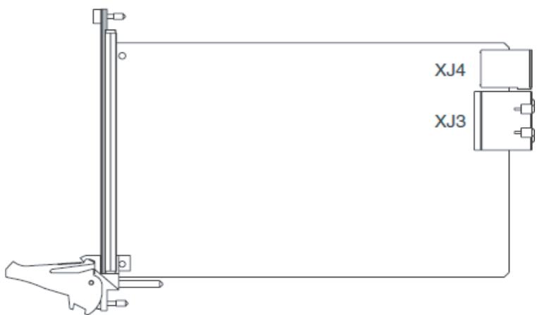
3 PXI Express peripheral slots are provided in the PXES- 2596E, all slots connected with PCIe x4 Gen3 lanes. Each can only accommodate a 3U PXI Express Compact- PCI Express peripheral module.
![XJ4\nJ1](.pxes-2596-50m-70434-1000-05/9053f07496c9e8b136db2a22b5a35799de98903460cd708c8ab7712a56731c59.jpg)

Figure 8: 3U hybrid slot compatible PXI-1 peripheral module
![XJ4\nXJ3](.pxes-2596-50m-70434-1000-05/59a5f9f34292d1a9a939440fe665d9c9649eb675f49e7222c025b5c82cd41ea3.jpg)

Figure 9: 3U PXI Express peripheral module

# Local Bus

The local bus on a PXI backplane is a daisy-chained bus that connects each peripheral slot with adjacent peripheral slots to the left and right. The quantity of local bus lines is decreased from thirteen to one on a PXI Express backplane. The remaining local bus line can transmit analog or digital signals between modules.

# Trigger Bus

The trigger bus is an 8-line bus that connects all slots on the PXES-2596, providing inter-module synchronization. PXI and PXI Express modules can exchange trigger or clock signals through the trigger bus, allowing precisely timed response to asynchronous external events the system is monitoring or con- trolling.

# Reference Clock

The PXES-2596 backplane supplies single-ended 10MHz reference clock (PXI\_CLK10) and differential 100MHz clock (PXIe\_CLK100) to each peripheral slot for inter-module synchronization. The independent buffers drive the clock signal to each peripheral slot.

These common reference clock signals can synchronize multiple modules in a PXI Express chassis. PXI modules with phase-lock loop circuits can lock reference clocks to generate an in-phase time base.

The PXI\_CLK10 and PXIe\_CLK100 clocks are in-phase according to the PXI-5 specification. Since the external 10MHz clock input can override the onboard 10MHz clock source, a phase-lock loop (PLL) circuit on the backplane synchronizes the PXIe\_CLK100 and external 10MHz clock.

# 2 Getting Started

This chapter describes procedures for installing the PXES-2596 and making preparations for its operation. Please contact ADLINK or authorized dealer if there are any problems during the installation

# 2.1 Power Supply Budget Considerations

Please review the power consumption of all modules used in the same PXES-2596. The total maximum power consumed by the system module and peripheral modules shall not exceed the DC power supply of the PXES-2596 as defined in DC Power Output.

# 2.2 Cooling Considerations

The PXES-2596 features an innovative design for heat dissipation, with cooling fans in the rear section of the chassis, drawing cool air through apertures on the bottom for exhaust through the back. This design provides uniform airflow for each PXI slot and exceptional cooling capability. When the chassis is installed in a rack, the cooling design minimizes drawing of hot air from the rear area, where other devices exhaust, while maintaining a steady temperature inside the chassis. For optimal cooling efficiency, retain support feet.

When rack mounting the PXES-2596, at least 1U (44.5 mm/1.75 in.) clearance below the intake apertures is required. Also keep other objects or equipment at a minimum of 76.2 mm (3 in.) away from the outlet apertures in the rear region of the chassis.

# 2.3 Cooling Configurations

Heat ventilation is related to the installation location, environmental temperature, and total heat generated by the system module and peripherals. The PXES-2596 features a smart fan function to provide sufficient ventilation and minimize noise emission. There is a switch located at rear of the chassis to configure the smart fan operation.

Auto - Enables smart fan function.

High - Full fan rotation utilization.

# 2.4 Hardware Installation

# 2.4.1 Installing the System Controller

The PXES-2596 incorporates a system controller slot supporting a PXI Express system controller of 3 or 4 slot widths. We recommend the ADLINK PXIe-3987 Controller for use with the PXES-2596.

1. Ensure the CPU, memory module(s), and storage device(s) are properly installed on the system controller.
2. Locate the system controller slot (Slot 1).
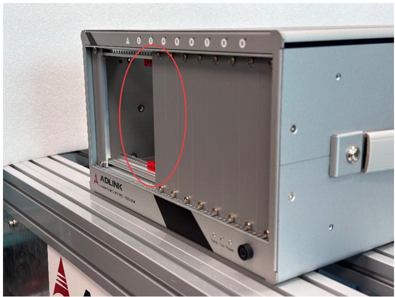
![Interior view of an ADLINK industrial control unit with labeled ports and a red circle highlighting a component (no readable text beyond label)](.pxes-2596-50m-70434-1000-05/a60519b3ef87f455f3f57143036665cbc7406726772bde06761c2b2b39608c4d.jpg)

3. Depress the system controller module’s latch to release.
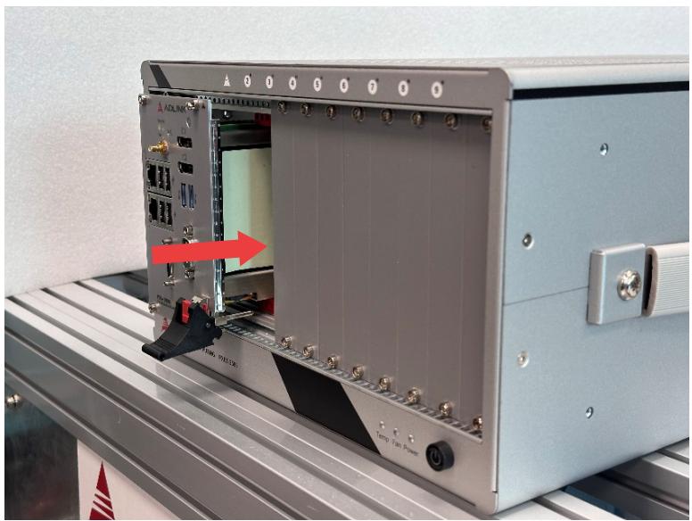
![Industrial control panel with labeled ports and a red arrow indicating a component (no readable text or symbols)](.pxes-2596-50m-70434-1000-05/4053766e6c6392d860a7605eb943c15cb89f2f0bb14d4f95ed52103cd4b27708.jpg)

4. Align the module’s top and bottom edges with the card guides, and carefully slide the module into the chassis.

5. Lift the latch until the module is securely seated in the chassis backplane.
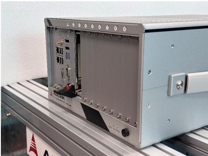
![Exterior view of a modern electronic device with visible internal components and labeled ports (no readable text or symbols)](.pxes-2596-50m-70434-1000-05/c4b485c4ef2bd8b6fb1cbcc3711487b71b7b96dca9397fd8e4f040c7a1b202ad.jpg)

6. Fasten the screws on the module front panel, and connect all devices to the system controller.
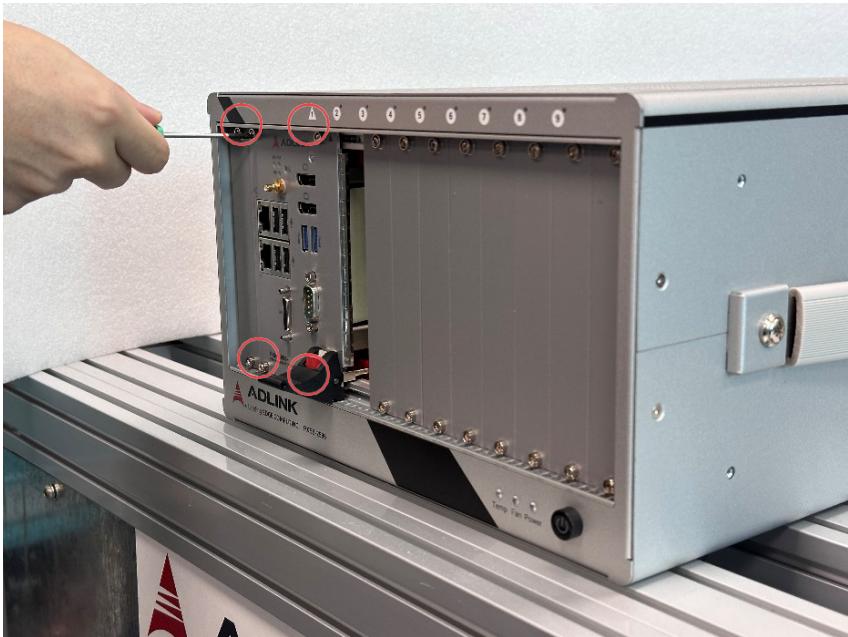
![ADLINK\nADLINK POWER\nTemp Gain Power](.pxes-2596-50m-70434-1000-05/1e2160704ea6adaf7dab7aceb45146db5081281838c2cf9264c49edfb3674e5a.jpg)

# 2.4.2 Installing Peripheral Modules

The PXE-2596 supports up to eight peripheral modules.

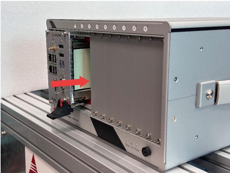
1. Select an available peripheral slot (2 to 9).
2. Depress the peripheral module’s latch and align the module’s top and bottom edges with the card guides.
![Industrial control panel with labeled ports and a red arrow pointing to a component (no readable text or symbols)](.pxes-2596-50m-70434-1000-05/458b7b14c1249be3ef2a42c21846ecb00820cf0b71a15a05713a5203b9213f7b.jpg)

3. Carefully slide the module into the chassis.
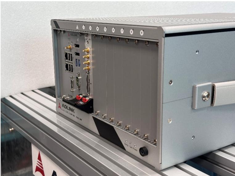
4. Lift the latch until the module is securely seated in the chassis backplane.
![Interior view of an ADLINK industrial control unit with visible ports and connectors (no readable text or symbols)](.pxes-2596-50m-70434-1000-05/ec9a36b14515215f68af151c27763c4742eeeeeff1e835801d83b5d3069b2369.jpg)

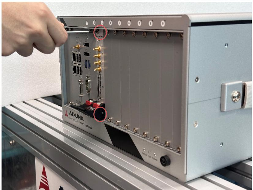
5. Fasten the screws on the module’s front panel.
![Close-up of an ADLINK industrial control module with visible ports and connectors, no readable text or symbols on the device itself.](.pxes-2596-50m-70434-1000-05/7128971bacb0febd007411b4acf17ebc10413ded41ab00026d366ca85eb8c183.jpg)

6. Repeat steps 1 to 5 to install additional PXI peripheral modules.

# 2.5 Rack Mounting

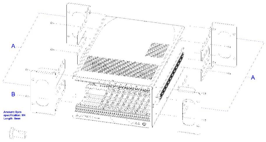
ADLINK provides hardware for optional installation of the PXES- 2596 to a rack. When mounted in a rack, the Rack-Mount kit(G) (part number 91-95115-0010) allows for adjustable placement of the PXES-2596 further back in the rack, thus allowing ample room at the front of the unit for external mechanical parts (such as cables and mass interconnect modules).
![A\nB\nAmount: 8pcs\nspecification: M4\nLength: 8mm](.pxes-2596-50m-70434-1000-05/ccea4e358a1fc7307f01f3b1e0ad7006621862d04817fb5293268db92d25cb82.jpg)

Figure 10: Rack Mount Assembly

<table><tr><td>Feature</td><td>Description</td></tr><tr><td>A</td><td>Mounting Brackets</td></tr><tr><td>B</td><td>Screws</td></tr></table>

To rack mount the PXES chassis, follow the steps below:

1. Remove carrying handle from the chassis right side.
2. Remove the four rubber feet from the chassis left side. Store the feet for later use, as they will not be needed for rack mount use.
3. Install the mounting brackets on both sides of the chassis using the provided M4 screws. Position of the mounting brackets can be adjusted along the screw holes to position the chassis forward or backward as needed.

Install the chassis and kit into the rack using eight screws (not included).

# 2.6 Powering Up the System

The PXES-2596 is equipped with a 100 VAC to 240 VAC universal power supply unit requiring no input voltage selection.

Do not to perform "hot swapping", replacement, disconnecting or connecting of any components (including cards and cabling) on chassis while the system is powered up. By not observing this Warning, system damage and/or data loss, and physical injury (due to possible shock hazard) may result.

To power up the system:

1. Connect one end of the supplied power cord to the power inlet located at the rear side of the chassis.
2. Plug the other end of the AC power cord to a properly grounded wall socket or power strip.
3. Press the power button. The Power LED (blue) lights up immediately.

# 2.7 PXES-2596 Software Resources

The following software resources are available for various application requirements.

# 2.7.1 ADLINK PXI Platform Services (APPS)

ADLINK PXI Platform Services is a software kit consisting of a utility and a group of software services and drivers.

# • ADLINK ChassisWatch

A GUI application program providing chassis status monitoring and configuration functions that are exclusive for all ADLINK PXI Express chassis.

# • PXI Express Chassis Software Services

API services and drivers for the PXES-2596 defined in the PXISA PXI-6 Software Specification.

# • PXI Resource Manager

A Windows background service following the PXI-2 and PXI-6 Software Specification to scan PXI/PXIe controllers, chassis, and peripheral modules and generate PXI system description files accordingly.

# • PXI Trigger Management Software Services

API services and Trigger Manager defined in PXISA PXI-9 PXI and PXI Express Trigger Management Specification.

Please refer to the ADLINK PXI Platform Services user manual for more information.

# 2.7.2 MAPS Core DAQ Software & Utility

Automation and Platform Services) software package includes ADLINK DAQ drivers, device management utility (ACE), and PXI configuration settings utility. Please refer to the MAPS Core user manual for more information.

# 3 System Management & Configuration

The PXES-2596 chassis provides advanced system monitoring and control. Chassis conditions, including internal temperature, fan speed, and DC voltage can all be monitored via ADLINK ChassisWatch — a Windows based utility for ADLINK PXIe chassis monitoring and configuration.

Communication with the chassis monitoring control unit is avail- able using an embedded controller, such as the ADLINK PXIe- 3987, via ADLINK ChassisWatch to access the SMBus located on the system slot (1st slot).

# 3.1 ChassisWatch

# 3.1.1 Chassis Status Monitor

Chassis conditions, including internal temperature, fan speed, and DC voltage can all be monitored by ChassisWatch running on an embedded PXI system controller or remote PC.

# 3.1.2 Smart Fan

When the Fan switch on the rear panel is set to AUTO, fans run at different speeds based on the measured temperature.

No target temperature needs to be set on PXES-2596, as it uses multiple fixed stages to control the fan speed, as shown in the table below.

<table><tr><td>Stage</td><td colspan="2">Thermal sensor reading temperature</td><td rowspan="2">Corresponding PWN Duty (%)</td></tr><tr><td>Event</td><td>Move to next stage</td><td>Return to last stage</td></tr><tr><td>1</td><td>55°C / 131°F</td><td>N/A</td><td>30</td></tr><tr><td>2</td><td>65°C / 149°F</td><td>51°C / 124°F</td><td>40</td></tr><tr><td>3</td><td>73°C / 163°F</td><td>61°C / 142°F</td><td>60</td></tr><tr><td>4</td><td>79°C / 174°F</td><td>69°C / 156°F</td><td>80</td></tr><tr><td>5</td><td>N/A</td><td>75°C / 167°F</td><td>100</td></tr></table>

# Appendix A - Troubleshooting and Maintenance

This Appendix describes basic troubleshooting techniques, as well as instructions for the maintenance of the PXES-2590 chassis.

# A.1 Installation Problems

Inability to start the system frequently results from incorrect installation of the system controller, peripheral modules, and other com- ponents. Before starting the system, please ensure that:

▶ The system controller is properly installed and secured
▶ All peripheral modules are properly seated on the slots
▶ All cables are properly connected to the system controller and peripheral modules
▶ All installed peripheral modules are compatible for use in the chassis

▶ The power cord is securely plugged into the chassis power connector and power outlet/wall socket/power strip

If the system fails to start when all installation conditions are met, remove all installed peripheral modules and try again. If the system starts normally, install one peripheral module at a time followed by powering up. You may also try installing the modules into different slots until the desired result is obtained.

A.2 Basic Troubleshooting

<table><tr><td>Problem</td><td>Ensure that:</td></tr><tr><td>System fails to power up</td><td>The power cord is securely plugged into the chassis power connector and wall socket/power stripThe wall socket/power strip is liveThe main power switch on the back of the chassis is turned onThe standby power button on the chassis front panel is turned on</td></tr><tr><td>No video output in the external display</td><td>The external display is function- ing properlyDisplay settings support external video.</td></tr><tr><td>Power LED (blue) is blinking</td><td>There is no short circuit by removing all PXI modules (PXI controller and peripheral mod- ules)If the signal persists, contact your dealer for further assistance</td></tr><tr><td>Fan LED (green) is blinking</td><td>The fan is unobstructedIf the signal persists, contact your dealer for further assistance.</td></tr><tr><td>Temperature LED (amber) is blinking</td><td>Airflow from the outlet apertures is unobstructed and steady; if not, ensure that adequate clearance for the intake apertures is pro- videdIf the temperature of exhausted air is normal (below 50°C) but the temperature LED is still blinking, contact your dealer for further assistance.</td></tr></table>

# A.3 Maintenance

# 1. Handling the Chassis

The PXES-2596 is designed for both rack-mount and benchtop use. When transporting or carrying the chassis, it is recommended that the handle be used, being designed to support the weight of the chassis for superior portability and balance.

The PXES-2596 weights 11 kg. Please be careful when moving the chassis to avoid any possible injury.

# 2. Cleaning the Exterior

Make sure that the system is turned off before cleaning the chas- sis exterior. Wipe the exterior with a clean cloth starting from areas that easily accumulate dust or dirt such as the area in and around the chassis and power supply air intake apertures.

# 3. Power Requirements

Make sure that the power cord is in good condition before plugging it into the system. It is important to check the reliability of the power source. The PXES-2596 power supply is capable of han- dling 100 to 240 V AC within the 50 Hz to 60 Hz range. Do not connect the PXES-2596 to an already overloaded circuit.

# Safety Instructions

Read and follow all instructions marked on the product and in the documentation before you operate your system. Retain all safety and operating instructions for future use.

Please read these safety instructions carefully.
• Please keep this User‘s Manual for later reference.
• Read the specifications section of this manual for detailed information on the operating environment of this equipment.
• When installing/mounting or uninstalling/removing equipment, turn off the power and unplug any power cords/cables.
• To avoid electrical shock and/or damage to equipment:

Keep equipment away from water or liquid sources.
Keep equipment away from high heat or high humidity.
 Keep equipment properly ventilated (do not block or cover ventilation openings).
 Make sure to use recommended voltage and power source settings.
 Always install and operate equipment near an easily accessible electrical socket-outlet.
Secure the power cord (do not place any object on/over the power cord).
 Only install/attach and operate equipment on stable surfaces and/or recommended mountings.
 If the equipment will not be used for long periods of time, turn off and unplug the equipment from its power source.

• Never attempt to fix the equipment. Equipment should only be serviced by qualified personnel.

For indoor use only.

Altitude during operation: up to 2000 m.

Over voltage category: OVC II

Pollution degree: 2

Ingress protection: X0

# Getting Service

Ask an Expert: https://www.adlinktech.com/en/Askanexpert

# ADLINK Technology, Inc.

Address: No. 66, Huaya 1st Road, Guishan District Taoyuan City 333, Taiwan

Tel: +886-3-216-5088

Fax: +886-3-328-5723

Email: service@adlinktech.com

# Ampro ADLINK Technology, Inc.

Address: 6450 Via Del Oro, San Jose, CA 95119-1208, USA

Tel: +1-408-360-0200

Toll Free: +1-800-966-5200 (USA only)

Fax: +1-408-600-1189

Email: info@adlinktech.com

# ADLINK Technology (China) Co., Ltd.

Address: 300 Fang Chun Rd., Zhangjiang Hi-Tech Park, Pudong New Area Shanghai, 201203 China

Tel: +86-21-5132-8988

Fax: +86-21-5132-3588

Email: market@adlinktech.com

# ADLINK Technology GmbH

Address: Hans-Thoma-Strasse 8-10, D-68163, Mannheim, Germany

Tel: +49-621-43214-0

Fax: +49-621 43214-30

Email: emea@adlinktech.com

Please visit the Contact page at www.adlinktech.com for information on how to contact the ADLINK regional office nearest you.
[🔗 Link to the original document](.pxes-2596-50m-70434-1000-05/pxes-2596-50m-70434-1000-05.pdf)