# PXES-2785

# 18-Slot PXI Express Chassis

# User’s Manual

![Exterior view of a ADLINK PXES-2785 industrial control unit (no visible text or symbols on the device body)](.pxes-2785-50-14013-1010-12/6bb589fed7688232b63e366c984ade47d9f1edd15fa114110d6479f60514b059.jpg)

Manual Rev.: 1.2

Revision Date: September 24, 2020

Part No: 50-14013-1010

Revision History

<table><tr><td>Revision</td><td>Release Date</td><td>Description of Change(s)</td></tr><tr><td>1.0</td><td>2019-10-02</td><td>Initial release</td></tr><tr><td>1.1</td><td>2020-06-08</td><td>Update specifications; add TUV safety content</td></tr><tr><td>1.2</td><td>2020-09-24</td><td>Updated specifications and images</td></tr></table>

# Preface

# Copyright © 2020 ADLINK Technology, Inc.

This document contains proprietary information protected by copyright. All rights are reserved. No part of this manual may be reproduced by any mechanical, electronic, or other means in any form without prior written permission of the manufacturer.

# Disclaimer

The information in this document is subject to change without prior notice in order to improve reliability, design, and function and does not represent a commitment on the part of the manufacturer.

In no event will the manufacturer be liable for direct, indirect, special, incidental, or consequential damages arising out of the use or inability to use the product or documentation, even if advised of the possibility of such damages.

ADLINK is committed to fulfill its social responsibility to global environmental preservation through compliance with the European Union's Restriction of Hazardous Substances (RoHS) directive and Waste Electrical and Electronic Equipment (WEEE) directive. Environmental protection is a top priority for ADLINK. We have enforced measures to ensure that our products, manufacturing processes, components, and raw materials have as little impact on the environment as possible. When products are at their end of life, our customers are encouraged to dispose of them in accordance with the product disposal and/or recovery programs prescribed by their nation or company.

![Symbol of a trash bin crossed with a diagonal line and a horizontal bar below (no text or labels)](.pxes-2785-50-14013-1010-12/7073cb96e3fa7d2ea6b05e69e590092a4e091ff31e74bb24e513870489edc6ad.jpg)

Battery Labels (for products with battery)
![Symbol of a trash bin crossed out by two diagonal lines (no text or numbers present)](.pxes-2785-50-14013-1010-12/0b2e22cea741299c60070d6ebc654302f8e5538ec3db546c0a7d33660f6a3862.jpg)

![Recycling symbol icon with three chasing arrows inside a square frame (no text or labels)](.pxes-2785-50-14013-1010-12/9124a9f549edf285d397cb755bf92b5ef1409d8baae4c954348690193c953253.jpg)

Li-ion

![RECYCLE\nRBRC\nLi-ion\n1.800.822.8837](.pxes-2785-50-14013-1010-12/df3f27afde3a3164ce6da5f808a49fc53472e1ea8c0fba9f9d16d1a7944bec47.jpg)

![Abstract geometric pattern with interlocking X and Y shapes (no text or symbols)](.pxes-2785-50-14013-1010-12/b824de72216c2cdbf3cde1e054056df0b10dfb505c845713eecac1d77768ab32.jpg)

ᘄ㟁ụㄳᅇᨲ

# California Proposition 65 Warning

![This image displays a standard warning sign: a yellow equilateral triangle with a thick black border. Centered inside the triangle is a black exclamation point. The background outside the triangle is white.](.pxes-2785-50-14013-1010-12/10d0faeee51d4a57849f7f712c2e52c50b41b19108c750c55f2a0e848720afbb.jpg)

WARNING: This product can expose you to chemicals including acrylamide, arsenic, benzene, cadmium, Tris(1,3-dichloro-2-propyl)phosphate (TDCPP), 1,4-Dioxane, formaldehyde, lead, DEHP, styrene, DINP, BBP, PVC, and vinyl materials, which are known to the State of California to cause cancer, and acrylamide, benzene, cadmium, lead, mercury, phthalates, toluene, DEHP, DIDP, DnHP, DBP, BBP, PVC, and vinyl materials, which are known to the State of California to cause birth defects or other reproductive harm. For more information go to www.P65Warnings.ca.gov.

# Trademarks

Product names mentioned herein are used for identification purposes only and may be trademarks and/or registered trademarks of their respective companies.

# Conventions

Take note of the following conventions used throughout this manual to make sure that users perform certain tasks and instructions properly.

![The image displays a white document icon with a folded top-right corner and horizontal gray lines representing text. A large, thick red checkmark is superimposed over the document, angled diagonally from the bottom left to the top right.](.pxes-2785-50-14013-1010-12/480f798e2174c3ab03162f5f4a27671c09d43c261dc9fa23826e1bd700f46042.jpg)
NOTE:

Additional information, aids, and tips that help users perform tasks.

![The image displays a yellow triangular warning sign with a black border. Centered within the triangle is a large black exclamation mark.](.pxes-2785-50-14013-1010-12/72e85dd228fec2659cf850feb8445d56829778ea51d0c6104c07ee36e3fa212f.jpg)
CAUTION:

Information to prevent minor physical injury, component damage, data loss, and/or program corruption when trying to complete a task.

![The image displays a red triangular warning sign with a white border. Inside the triangle is a large white exclamation mark centered vertically.](.pxes-2785-50-14013-1010-12/bb4c02f63ada5446573b6e6336703d4555ee55f119505fdddfc21c021dc43346.jpg)
WARNING

Information to prevent serious physical injury, component damage, data loss, and/or program corruption when trying to complete a specific task.

# Table of Contents

# Revision History........ ii

# Preface ............. iii

# List of Figures ........ .... vii

# List of Tables...... ix

# 1 Introduction ......

1.1 Features...... 2
1.2 Specifications..... 3
1.3 Connectors, I/O and Controls .. 15

1.3.1 Front Panel ... .. 15
1.3.2 Rear Panel.... .. 16
1.3.3 Positions of Backplane Thermal Sensors..... .. 19
1.3.4 PCI Express.... .... 20

# 2 Getting Started ..... 2 9

2.1 Package Contents .... 29
2.2 Power Supply Budget Considerations .. 3 0
2.3 Cooling Considerations.. 30
2.4 Configure Settings for Cooling ....... 30

2.4.1 Fan Mode Switch. .. 31
2.4.2 Fan Speed Switch .. .. 31

2.5 Hardware Installation .... 32

2.5.1 Installing the System Controller .... . 32
2.5.2 Installing Peripheral Modules . 37

2.6 Rack Mounting.. 40

2.6.1 Powering Up the System ..... .. 41

2.7 PXES-2785 Software Resources.. 42

2.7.1 ADLINK PXI Platform Services (APPS).... . 42
2.7.2 MAPS Core DAQ Software & Utility ..... .. 42

# 3 System Management & Configuration .................. 43

# 3.1 ChassisWatch... 44

3.1.1 Chassis Status Monitor.. .. 44
3.1.2 Software Configurable PXI Trigger Bus Bridges....... 44
3.1.3 Smart Fan ...... .. 46

# 3.2 Remote Management LAN Port... 48

# A Appendix: Maintenance....... .....49

A.1 Installation Problems.. 49
A.2 Basic Troubleshooting ...... 50
A.3 Maintenance .. 51

A.3.1 Handling the Chassis... ... 51
A.3.2 Cleaning the Exterior .. .. 51
A.3.3 Power Requirements . .. 51
A.3.4 Replacing the Power Supply Module..... .. 52

# Important Safety Instructions........ ..... 55

# Consignes de Sécurité Importante ........ .. 58

# Getting Service ......... ...... 61

# List of Figures

Figure 1-1: Backplane PCI Express Bus Topology... 7

Figure 1-2: Front View . . 10

Figure 1-3: Right View .. .. 11

Figure 1-4: Left View .... . 11

Figure 1-5: Bottom View ..... .. 12

Figure 1-6: PXES-2785 Front Panel . .. 15

Figure 1-7: PXES-2785 Rear Panel.. .. 16

Figure 1-8: PXES-2785 Backplane Thermal Sensor Positions... 19

Figure 1-9: Star Trigger & Differential Star Bus Routing ............. 21

Figure 1-10: 3U Hybrid Slot Compatible PXI-1 Peripheral Module23

Figure 1-11: 3U PXI Express Peripheral Module .... .. 24

Figure 1-12: Trigger Bus and Bus Bridges.. .. 25

Figure 1-13: Trigger Bus Bridge Routing . .. 26

Figure 2-1: System Controller Slot Location (Slot 1)....... .. 32

Figure 2-2: Depress Module Release Latch . . 33

Figure 2-3: Align System Controller Module . . 34

Figure 2-4: Secure System Controller Module Latch ...... .... 35

Figure 2-5: Fasten System Controller Module Screws ............... 36

Figure 2-6: Insert Peripheral Module into Chassis... .. 37

Figure 2-7: Secure Peripheral Module Latch .. .. 38

Figure 2-8: Fasten Peripheral Controller Module Screws ........... 39

Figure 2-9: Rack Mount Assembly... .. 40

Figure 3-1: Chassis ChassisWatch GUI Application Utility ......... 44

Figure 3-2: Trigger Bus Routing Settings. .. 45

Figure 3-3: Target Temperature Parameters ... .. 46

Figure 3-4: Chassis Status Monitor... .. 48

This page intentionally left blank.

# List of Tables

Table 1-1: Power Supply Specifications .. 3

Table 1-2: DC Power Output Specifications .. 4

Table 1-3: Backplane Slot DC Power Current . 4

Table 1-4: PXI 10 MHz Reference Clock.. 4

Table 1-5: External 10 MHz Clock Output . 5

Table 1-6: External Clock Input Requirements . . 5

Table 1-7: PXI Star Trigger ... . 5

Table 1-8: PXI Express 100 MHz System Reference Clock............. 6

Table 1-9: PXI Differential Star Triggers .. 6

Table 1-10: Backplane Slots & Functionality . 1

Table 1-11: Ventilation (Heat Dissipation) . 8

Table 1-12: Cooling . . 9

Table 1-13: Mechanical Dimensions and Weight.. . 10

Table 1-14: PXI Express Slot Pin Definitions... . 13

Table 1-15: Environmental Specifications... . 14

Table 1-16: Front Panel Power & Status . . 15

Table 1-17: Front Panel Indicators... .. 16

Table 1-18: Rear Panel Legend.. .. 17

Table 1-19: Voltage Monitor / Remote Control Connector... .. 18

Table 1-20: Star Trigger & Differential Star Bus Assignments.......... 22

Table 1-21: PXES-2785 Reference Clock Priority .. . 27

Table 2-1: Rack Mount Assembly Legend. .. 40

Table 3-1: Target Temperature Parameters Legend . .. 47

Table 3-2: LAN Port Default IP Settings . .. 48

This page intentionally left blank.

# 1 Introduction

The ADLINK PXES-2785 chassis combines a high-performance 18-slot PXI Express backplane with a high-output power supply and a structural design that has been optimized for maximum usability in a wide range of applications. The chassis' modular design ensures a high level of maintainability and offers replaceable power supplies for high-availability applications, resulting in a very low mean time to repair (MTTR). The PXES-2785 chassis fully complies with the PXI™-5 PXI Express Hardware Specification, offering advanced timing and synchronization features.

ADLINK PXES-2785, using PCI Express 3.0 technology, features 24 GB/s of system bandwidth for high-throughput, peer-to-peer data transfer applications, and up to 8 GB/s bandwidth for all peripheral slots. Moreover, the chassis offers 990W power in total, and 50W of power cooling capacity per slot so that the PXES-2785 can provide higher power budgets for high performance and power PXI modules. The PXI Express timing and synchronization functions are for high clock accuracy and external clock and trigger routing.

The PXES-2785 is equipped with a smart system monitoring controller, reporting chassis status including fan speed, system voltages, and internal temperature, remote chassis monitoring via Ethernet port, and inhibit control.

# 1.1 Features

 PXI-5 PXI Express hardware specification Rev.1.1 compliant
18-slot PXI Express chassis with one system slot, one system timing slot, six hybrid peripheral slots, and ten PXI Express peripheral slots
 PXI Express System Slot routed as 2 Link Configuration x8 x16
 Up to 24 GB/s (PCI Express x8 x16 Gen3 link) system bandwidth
 Up to 8 GB/s (PCI Express x8 Gen3 link) bandwidth for all peripheral slots
 Low-jitter internal 10 MHz reference clock for PXI/PXI Express slots with ±1 ppm stability
 Low-jitter internal 100 MHz reference clock for PXI Express slots with ±1 ppm stability
 0°C to 55°C extended operating temperature range
 Two BNC connectors for PXI 10MHz reference clock input and output
 Replaceable fan and power supply module for maintenance
 Variable speed fan controller optimizes cooling and acoustic emissions
 Through inhibit connector, including remote power button and voltage monitor

# 1.2 Specifications

The PXES-2785 complies with the PXI-5 Specification Rev.1.1 and accepts all modules compliant with the PXI-5, CompactPCI, and PICMG 2.0 specifications.

Power Supply

<table><tr><td colspan="2">AC Power Input</td></tr><tr><td>Rated Input</td><td>100-240 VAC, 50-60Hz, 1300W max.</td></tr><tr><td>Over-current protection</td><td>16 A resettable breaker in AC input line</td></tr></table>

<table><tr><td colspan="2">Entrée d&#x27;alimentation CA</td></tr><tr><td>Entrée nominale</td><td>100-240 VAC, 50-60Hz, 1300W max.</td></tr><tr><td>Protection contre les surintensités</td><td>16 A disjoncteur réarmable dans la ligne d&#x27;entrée AC</td></tr></table>

Table 1-1: Power Supply Specifications

DC Power Output

<table><tr><td colspan="3">Operation Ambient Temperature</td><td colspan="2">Maximum Total DC Output</td></tr><tr><td colspan="3">45C to 55°C, 113°F to 131°F</td><td colspan="2">990 W max. (200 to 240VAC), 790 W max. (100 to 120VAC)</td></tr><tr><td colspan="3">0C to 45°C, 32°F to 113°F</td><td colspan="2">1170 W max. (200 to 240VAC), 1000 W max. (100 to 120VAC)</td></tr><tr><td>Voltage Rail</td><td>Maximum Total Current</td><td colspan="2">Load Regulation</td><td>Maximum Ripple Noise</td></tr><tr><td>+12V</td><td>72A</td><td colspan="2">±5%</td><td>120mV</td></tr><tr><td>+3.3V</td><td>77A</td><td colspan="2">±5%</td><td>50mV</td></tr><tr><td>+5V</td><td>20A</td><td colspan="2">±5%</td><td>50mV</td></tr><tr><td>-12V</td><td>4A</td><td colspan="2">±5%</td><td>120mV</td></tr><tr><td>+5Vaux</td><td>4A</td><td colspan="2">±5%</td><td>50mV</td></tr></table>

Table 1-2: DC Power Output Specifications

Backplane Slot DC Power Current

<table><tr><td>Slot Type</td><td>Slot Number</td><td>+5V</td><td>+3.3V</td><td>+12V</td><td>-12V</td><td>+5Vaux</td></tr><tr><td>PXle System Slot</td><td>1</td><td>15A</td><td>15A</td><td>30A</td><td>-</td><td>3A</td></tr><tr><td>PXle Peripheral/System Timing Slots</td><td>2, 3, 4, 5, 6, 10, 14, 15, 16, 17, 18</td><td>-</td><td>9A</td><td>6A</td><td>-</td><td>1A</td></tr><tr><td>PXle HybridPeripheral Slot</td><td>7, 8, 9, 11, 12, 13</td><td>6A</td><td>9A</td><td>6A</td><td>1A</td><td>1A</td></tr></table>

Table 1-3: Backplane Slot DC Power Current

PXI 10 MHz System Reference Clock (PXI\_CLK10)

<table><tr><td>Item</td><td>Detail</td></tr><tr><td>Maximum slot-to-slot skew</td><td>280 ps</td></tr><tr><td>Accuracy</td><td>±1 ppm max, 0°C to 55°C, 32°F to 131°F</td></tr><tr><td>Maximum jitter</td><td>0.44 ps RMS phase-jitter (12k Hz–20 MHz)</td></tr><tr><td>Duty-factor for PXI_CLK10</td><td>45% to 55%</td></tr><tr><td>Unloaded signal swing</td><td>3.3V ± 5% (±0.165V)</td></tr></table>

Table 1-4: PXI 10 MHz Reference Clock

External 10 MHz Clock Output

<table><tr><td>Item</td><td>Detail</td></tr><tr><td>Accuracy</td><td>±1 ppm max, 0°C to 55°C, 32°F to 131°F</td></tr><tr><td>Maximum jitter</td><td>2.14 ps RMS phase-jitter (12k Hz–20 MHz)</td></tr><tr><td>Output amplitude</td><td>1 Vpp ±20% square-wave into 50Ω,2 Vpp unloaded</td></tr><tr><td>Output impedance</td><td>50Ω ±5Ω</td></tr></table>

Table 1-5: External 10 MHz Clock Output

External 10 MHz Clock Source Input Requirements

<table><tr><td>Item</td><td>Detail</td></tr><tr><td>Frequency input</td><td>10 MHz ±25 PPM</td></tr><tr><td>Input signal (10MHz REF In BNC)</td><td>100 mVPP to 5 VPP (square or sine)</td></tr><tr><td>Input impedance (10MHz REF In BNC)</td><td>High impedance</td></tr><tr><td>Input signal (PXI_CLK10_IN on 10th slot)</td><td>5 V or 3.3 V TTL signal</td></tr></table>

Table 1-6: External Clock Input Requirements

PXI Star Trigger

<table><tr><td>Item</td><td>Detail</td></tr><tr><td>Maximum slot-to-slot skew</td><td>250ps</td></tr><tr><td>Backplane characteristic impedance</td><td> $50\Omega \pm 5\Omega$ </td></tr></table>

Table 1-7: PXI Star Trigger

PXIe 100 MHz System Reference Clock (PXIe\_CLK100)

<table><tr><td>Item</td><td>Description</td></tr><tr><td>Maximum slot-to-slot skew</td><td>100 ps</td></tr><tr><td>Accuracy</td><td>±1 ppm max, 0°C to 55°C, 32°F to 131°F</td></tr><tr><td>Maximum jitter</td><td>2.41 ps RMS phase-jitter (12k Hz–20 MHz)</td></tr><tr><td>Duty-factor for PXIe_CLK100</td><td>45% to 55%</td></tr><tr><td>Absolute differential voltage (when terminated with a 50 Ω load to 1.30 V or Thévenin equivalent)</td><td>400 to 900 mV</td></tr><tr><td>PXIe_SYNC100</td><td>Implemented as default behavior.PXIe_SYNC_CTRL is disabled by connecting a 10kΩ pull-down resistor to ground.</td></tr></table>

Table 1-8: PXI Express 100 MHz System Reference Clock

# PXI Differential Star Triggers

(PXIe-DSTARA, PXIe-DSTARB, PXIe-DSTARC)

<table><tr><td>Item</td><td>Detail</td></tr><tr><td>Maximum slot-to-slot skew</td><td>150ps</td></tr><tr><td>Maximum differential skew</td><td>25ps</td></tr><tr><td>Backplane differential impedance</td><td>100Ω ±10Ω</td></tr><tr><td>Maximum Channel Bandwidth</td><td>1.75GHz</td></tr></table>

Table 1-9: PXI Differential Star Triggers

Backplane Slots & Functionality

<table><tr><td>Type of Slot</td><td>Qty</td><td>Slot Number</td><td>Bus</td></tr><tr><td>PXI Express System Slot</td><td>1</td><td>1</td><td>2 Link x8 x16 (Note 1)</td></tr><tr><td>PXI Express System Timing Slot</td><td>1</td><td>10</td><td>(Note 2)</td></tr><tr><td>PXI Express Hybrid Peripheral Slot</td><td>6</td><td>7,8,9,11,12,13</td><td>(Note 2)</td></tr><tr><td>PXI Express Peripheral Slot</td><td>10</td><td>2,3,4,5,6,14,15, 16,17,18</td><td>(Notes 2, 3)</td></tr></table>

Table 1-10: Backplane Slots & Functionality

# Notes:

1. PCIe x8 x16 Gen3 supports up to 24 GB/s system bandwidth.
2. PCIe x8 Gen3 supports up to 8 GB/s peripheral bandwidth.
3. PCI Bus 32-bit at 33 MHz and 5 VIO.

Backplane PCI Express Bus Topology
PXES-2785 Backplane PCI Express Bus Fabric - 2 Link x16 x8
![Based on the provided image, here is the accurate and concise description of the flowchart:\n\n**Labeled Blocks:**\n*   **Top Level:** Two large light blue rectangles labeled 'PCI Express Switch Fabric'.\n*   **Inputs:**\n    *   An orange box labeled 'Gen3 x16' (top left).\n    *   An orange box labeled 'Gen3 x8' (top right).\n*   **Middle Row (Interconnects):** A series of smaller orange boxes labeled 'Gen3 x8'. There are 16 of these boxes arranged in a row below the switch fabrics (8 under the left fabric and 8 under the right fabric).\n*   **Bottom Row (Slots):** A series of server slots labeled 'Slot 01' through 'Slot 18' in blue text.\n*   **Bottom Right Components:**\n    *   A gray box labeled 'Gen1 x1'.\n    *   A white box labeled 'PCIe To PCI Bridge'.\n    *   A gray box labeled 'PCI Bus 32-bit (33MHz 5VIO)'.\n\n**Connections:**\n*   **From 'Gen3 x16':**\n    *   An orange arrow points to the right, entering the left 'PCI Express Switch Fabric'.\n    *   An orange arrow points down and to the left, connecting to the area above 'Slot 01'.\n*   **From Top Right 'Gen3 x8':**\n    *   An orange arrow points down and to the left, entering the right 'PCI Express Switch Fabric'.\n*   **From Middle Row 'Gen3 x8' Boxes:**\n    *   Orange arrows point upward from each 'Gen3 x8' box to the respective 'PCI Express Switch Fabric' block above it.\n    *   The left fabric sits above 'Slot 02' through 'Slot 09'.\n    *   The right fabric sits above 'Slot 10' through 'Slot 17'.\n*   **From 'Slot 18':**\n    *   A blue arrow points upward to the 'Gen1 x1' box.\n*   **From 'Gen1 x1':**\n    *   A blue arrow points downward to the 'PCIe To PCI Bridge' box.\n*   **From 'PCI Bus 32-bit (33MHz 5VIO)':**\n    *   A blue arrow points to the left, extending towards the left side of the diagram.](.pxes-2785-50-14013-1010-12/733f58d7b0d297caf55fd242a865ceb47c5724d89ce88c5b6d18e306a399186e.jpg)

Figure 1-1: Backplane PCI Express Bus Topology

# Ventilation (Heat Dissipation)

<table><tr><td>Usage Mode</td><td>Temperature Range</td><td>Environment</td></tr><tr><td>When all peripheral modules require ≤38 W cooling capacity per slot, Set Fan mode as Normal.</td><td>0°C to 55°C, 32°F to 131°F (Notes 1, 3)</td><td rowspan="4">Indoor use only</td></tr><tr><td>When any of the peripheral modules require 38 to 50 W cooling capacity per slot, Set Fan mode as Boost.</td><td>0°C to 55°C, 32°F to 131°F (Notes 1, 3)</td></tr><tr><td>When any of the peripheral modules requires ≤82 W cooling capacity per slot, Set Fan mode as Boost.</td><td>0 °C to 45 °C, 32°F to 113°F (Notes 2, 3)</td></tr><tr><td>Relative humidity range</td><td>10% to 90%, non-condensing (Note 4)</td></tr></table>

Table 1-11: Ventilation (Heat Dissipation)

# Notes:

1. Install Wind Block Module on all vacant slots.
2. The modules in the adjacent 2 left and 2 right slots of the 82W modules should be less than 50W. If vacant, install Wind Block Module.
3. Validation complies with IEC 60068-2-1 and IEC 60068- 2-2.
4. Validation complies with IEC-60068-2-30.

# Cooling

<table><tr><td>Item</td><td>Detail</td></tr><tr><td>Chassis Rear Fans (for peripheral modules)</td><td>Forced air circulation through 3x 220 CFM fans</td></tr><tr><td>Chassis Side Fan (for power module)</td><td>Power supply unit integrated fan</td></tr><tr><td>Module slot airflow direction</td><td>From bottom to top of module</td></tr><tr><td>Module airflow intake</td><td>Bottom and Side of front part of chassis</td></tr><tr><td>Module airflow exhaust</td><td>Rear of chassis</td></tr><tr><td>System Module Slot cooling capacity</td><td>Maximum 150 W</td></tr><tr><td>Peripheral Module Slot cooling capacity</td><td>Maximum 82 W</td></tr><tr><td>Power supply cooling</td><td>Forced air circulation through integrated fan</td></tr><tr><td>Power supply intake</td><td>Right side of chassis</td></tr><tr><td>Power supply exhaust</td><td>Rear of chassis</td></tr><tr><td>Minimum chassis cooling clearances</td><td>Rear: 101.60 mm (4.00 in.)Side: 44.45 mm (1.75 in.)Bottom: 17.00 mm (0.67 in.)</td></tr></table>

Table 1-12: Cooling

![The image displays a yellow triangular warning sign with a black border. Inside the triangle is a black exclamation point. Below the triangle, the text 'CAUTION:' is printed in black capital letters.](.pxes-2785-50-14013-1010-12/62a39b21cbee190a67afc97365ecbc8e97115543e25c754d0aadf7ea2507a1d7.jpg)

Do not block ventilation holes. Ensure sufficient cooling clearances for the front, bottom, sides, and rear of chassis.

# Mechanical Dimensions and Weight

<table><tr><td>Item</td><td>Detail</td></tr><tr><td>Height</td><td>194.8mm (7.67&quot;)</td></tr><tr><td>Width</td><td>457.4mm (18.01&quot;)</td></tr><tr><td>Depth</td><td>480.5mm (18.92&quot;)</td></tr><tr><td>Net Weight</td><td>11.9 kg (26.2 lbs)</td></tr><tr><td>Gross Weight(with package, power cable, and filler panels)</td><td>14.6 kg (32.2 lbs)</td></tr></table>

Table 1-13: Mechanical Dimensions and Weight

![(All dimensions in millimeters)\n457,4\n13,0\nADLINK\nP225-2785\nP281\n19,0\n432,4\n6,0](.pxes-2785-50-14013-1010-12/d2fd668c4225bb21917f9613e1b965cdc303948634b9133fd2ee14dd58c53e45.jpg)

Figure 1-2: Front View

![Technical line drawing of a device rear panel with ports and connectors (no text or symbols)](.pxes-2785-50-14013-1010-12/72d71c3059be46b28473b2a8e851bea3cbe8c831bc941f63d6e093bcaebad6fb.jpg)

Figure 1-3: Right View

![480,5\n33,9\n194,8\n17,0\n68,0\n415,0\n30,5\n11,5](.pxes-2785-50-14013-1010-12/d9524f8ac8cb21e646d4917aca5a740a980a01fe7d48e280cc736f8162954300.jpg)

Figure 1-4: Left View

![Technical line drawing of a rectangular electronic device with grid pattern and mounting feet (no text or symbols)](.pxes-2785-50-14013-1010-12/399e03cf69f695c0629f9ac1c6d948fbe9d1faac58ad2dd0823f00e487842a37.jpg)

Figure 1-5: Bottom View

# Pin Definitions

<table><tr><td>Slot Type</td><td>Pin Definition</td></tr><tr><td>PXI Express System Slot</td><td>Comply with PXISA PXI-5 Hardware Specification: PXI Express System Slot Pin Assignments for 2 Link Operation</td></tr><tr><td>PXI Express System Timing Slot</td><td>Comply with PXISA PXI-5 Hardware Specification: PXI Express System Timing Slot Pinout</td></tr><tr><td>PXI Express Peripheral Slot</td><td>Comply with PXISA PXI-5 Hardware Specification: PXI Express Peripheral Slot Pin Assignments</td></tr><tr><td>PXI Express Hybrid Peripheral Slot</td><td>Comply with PXISA PXI-5 Hardware Specification: PXI Express Hybrid Peripheral Slot Pin Assignments</td></tr></table>

Table 1-14: PXI Express Slot Pin Definitions

# Software and Utilities

The PXES-2785 complies with PXI-6 PXI Express Software Specification Revision 1.2. Related software resources are available in following software packages.

# ADLINK PXI Software Service

A software package that provides PXI-2/PXI-6/PXI-9 software services, drivers, sample programs, and utilities for ADLINK PXI Express/PXI system modules and chassis. Please refer to the ADLINK PXI Platform Service user manual for more information.

# Measurement Automation and Platform Service (MAPS)

A software package including ADLINK DAQ drivers and ADLINK PXI Software Service. Please refer to the MAPS user manual for more information.

Environmental Specifications

<table><tr><td>Item</td><td colspan="2">Detail</td></tr><tr><td>Storage</td><td colspan="2">Ambient temperature: -20 to 70°CRelative humidity: 10 to 90%, noncondensing</td></tr><tr><td>Operating</td><td colspan="2">Ambient temperature: 0°C to 55°CRelative humidity10 to 90%, noncondensing</td></tr><tr><td>Functional shock</td><td colspan="2">30 G, half-sine, 11 ms pulse duration</td></tr><tr><td>Random Vibration</td><td colspan="2">Operating: 5 to 500 Hz, 0.3 Grms, 3 axesNonoperating: 5 to 500 Hz, 2.46 Grms, 3 axes</td></tr><tr><td>Fan Mode*</td><td>Fan Speed*</td><td>Acoustic Emissions</td></tr><tr><td rowspan="2">Normal</td><td>Auto</td><td>40.9 dBA (up to 25°C ambient)</td></tr><tr><td>High</td><td>51.0 dBA</td></tr><tr><td rowspan="2">Boost</td><td>Auto</td><td>46.1 dBA (up to 25°C ambient)</td></tr><tr><td>High</td><td>69.2 dBA</td></tr></table>

\*Fan Mode and Fan Speed are set by switches at the rear of the chassis.

Table 1-15: Environmental Specifications

# Electromagnetic Compatibility

EN 61326-1 (IEC 61326-1): Class A emissions; Basic immunity
 EN 55011 (CISPR 11): Group 1, Class A emissions
 EN 55032 2015/AC: 2016 Class A
 EN 55024 2010+ A1: 2015
 EN 61000-3-2:2014 : Class A
 EN 61000-3-3:2013 : Class A
 EN 55024:2010+A1:2015 : Immunity
 FCC 47 CFR Part 15 Subpart A (Class A)
 ICES-001 Class A
 ICES-003 Issue 6-2016
 AS/NZS CISPR 11: Group 1, Class A emissions
 AS/NZS CISPR 32: 2015 (Ed 2.0)/C1:2016 : Class A

# 1.3 Connectors, I/O and Controls

# 1.3.1 Front Panel
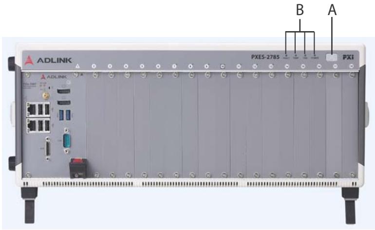
![ADLINK\nPXES-2785\nPXI\nB\nA](.pxes-2785-50-14013-1010-12/a6ac0f89e987cb7accab76150413edfe04f6b5073054bfebd9642a6283745abb.jpg)

Figure 1-6: PXES-2785 Front Panel

Front Panel Power & Status

<table><tr><td>Item</td><td>Feature</td><td>Description</td></tr><tr><td>A</td><td>Power</td><td>Powers the chassis on/off when INHIBIT on rear panel (not shown) is set to “DEF”</td></tr><tr><td>B</td><td>Chassis Status</td><td>Fault, Temperature Fan, Power (L to R)</td></tr></table>

Table 1-16: Front Panel Power & Status

Front Panel Indicators

<table><tr><td>Status</td><td>Fault (Red)</td><td>Temperature (Amber)</td><td>Fan (Green)</td><td>Power (Blue)</td></tr><tr><td>On (Lit)</td><td>N/A</td><td>N/A</td><td>Fans operating normally</td><td>DC voltage supply is normal</td></tr><tr><td>Off</td><td>Normal operation</td><td>Temperature is normal</td><td>Chassis is powered down</td><td>Chassis is powered down</td></tr><tr><td>Blinking</td><td>Abnormal, one or more chassis readings are over threshold.</td><td>One or more temperature sensors exceeds threshold temperature (default 70°C)</td><td>One or more fans falls below threshold speed (default is 800RPM)</td><td>One or more power rails exceeds threshold settings (defaults are ±5% for 5V, 3.3V, +12V, and -12V)</td></tr></table>

Table 1-17: Front Panel Indicators

# 1.3.2 Rear Panel

![100 V 200V - 50-60kW, 1100W MAX.\n320 V 340V - 50-60kW, 1200W MAX.\nCIRCUIT METER\nK J I H G F E D C\nPOWER\nMAX\nOUT\nMAX\nMAX\nMAX\nMAX\nMAX\nMAX\nMAX\nMAX\nMAX\nMAX\nMAX\nMAX\nMAX\nMAX\nMAX\nMAX\nMAX\nMAX\nMAX\nMAX\nMAX\nMAX\nMAX\nMAX\nMAX\nMAX\nMAX\nMAX\nMAX\nMAX\nMAX\nMAX\nMAX\nMAX\nMAX\nMAX\nMAX\nMAX\nMAX\nMAX\nMAX\nMAX\nMAX\nMAX\nMAX\nMAX\nMAX\nMAX\nMAX\nMAX\nMax\nMax\nMax\nMax\nMax\nMax\nMax\nMax\nMax\nMax\nMax\nMax\nMax\nMax\nMax\nMax\nMax\nMax\nMax\nMax\nMax\nMax\nMax\nMax\nMax\nMax\nMax\nMax\nMax\nMax\nMax\nMax\nMax\nMax\nMax\nMax\nMax\nMax\nMax\nMax\nMax\nMax\nMax\nMax\nMax\nMax\nMax\nMax\nMax\nMax\nMin](.pxes-2785-50-14013-1010-12/bb51a5ec37f24e9f0e07a9517048ed994d58e46dc8f4b26fa7694040807cc2c1.jpg)

Figure 1-7: PXES-2785 Rear Panel

Rear Panel Features

<table><tr><td>Item</td><td>Feature</td><td>Description</td></tr><tr><td>C</td><td>Voltage Monitor / Remote Control</td><td>See Voltage Monitor / Remote Control Connector on page 18 below.</td></tr><tr><td>D</td><td>Remote Management</td><td>The LAN port provides an HTTP web-based monitor page for displaying real time status of the PXES-2785. The default static IP address is 192.168.1.10 and the netmask is 255.255.255.0. The IP settings can be configured via ChassisWatch. ChassisWatch is part of the ADLINK PXI Software Service. Refer to the ADLINK PXI Software Service user manual for more information.</td></tr><tr><td>E</td><td>10MHz Reference Clock Input</td><td>The BNC connector acts as a 10MHz reference clock input, whereby the backplane 10MHz clock is overridden in the presence of an external 10MHz clock</td></tr><tr><td>F</td><td>10MHz Reference Clock Output</td><td>The BNC connector acts as 10MHz reference clock output.</td></tr><tr><td>G</td><td>Inhibit Switch</td><td>DEF: Power ON/OFF (ATX mode) is controlled by the power button on the front panel and Pin10 PWRBTN# on the rear connector.MAN: Power ON/OFF (AT mode) is controlled by Pin9 INHIBIT#.</td></tr><tr><td>H</td><td>Fan Speed Switch</td><td>HIGH: Disables Smart Fan function.Sets fan speeds of rear 3 fans to max. RPM.AUTO: Enables Smart Fan function.Auto fan speed based on Fan Mode Switch setting.</td></tr><tr><td>I</td><td>Fan Mode Switch</td><td>BOOST: Sets Smart Fan to boost mode:Auto fan speed based on temperature with enhanced ventilation performance.NORMAL: Sets Smart Fan to normal mode:Auto fan speed based on temperature with balanced performance between ventilation and acoustic emission.</td></tr><tr><td>J</td><td>AC Circuit Breaker</td><td>100 to 240 VAC 16A resettable breaker in AC input line.</td></tr><tr><td>K</td><td>Universal Power Inlet</td><td>Accepts IEC 60320-1 C19 power outlet-equipped connection.</td></tr></table>

Table 1-18: Rear Panel Legend

Voltage Monitor / Remote Control Connector

<table><tr><td>Pin</td><td>Signal</td><td>Type</td><td>Description</td></tr><tr><td>1</td><td>GND</td><td>GND</td><td>System Ground Pin for Pin 2 to10.</td></tr><tr><td>2</td><td>5VSB</td><td>Output</td><td>DC 5V stand-by monitor pin. Inline output current limit resistor 10KΩ.</td></tr><tr><td>3</td><td>12V</td><td>Output</td><td>DC 12V monitor pin. Inline output current limit resistor 10KΩ.</td></tr><tr><td>4</td><td>5V</td><td>Output</td><td>DC 5V monitor pin. Inline output current limit resistor 10KΩ.</td></tr><tr><td>5</td><td>3.3V</td><td>Output</td><td>DC 3.3V monitor pin. Inline output current limit resistor 10KΩ.</td></tr><tr><td>6</td><td>-12V</td><td>Output</td><td>Monitor pin of DC -12V. Inline output current limit resistor 10KΩ.</td></tr><tr><td>7</td><td>PWRGD</td><td>Output</td><td>High: Chassis power status is on.Low: Chassis power status is off or abnormal.VOH: 2.3V min (max current 24 mA)VOL: 0.55V max (max current 24 mA)</td></tr><tr><td>8</td><td>FAULT</td><td>Output</td><td>1Hz Pulse: One or more readings are over threshold settings of temperature, fan, and voltage.Low: All readings are under threshold settings.VOH: 2.3V min (max current 24 mA)VOL: 0.55V max (max current 24 mA)</td></tr><tr><td>9</td><td>INHIBIT#</td><td>Input, low active</td><td>Pin for remote power on/off chassis (AT mode). Valid when rear INHIBIT switch is set as MAN.Internal 1 kΩ pull-up to 5VSB and 10ms internal de-bounce.High or floating: Turn on all DC power output.Low: Turn off all DC power output.VIH: 2.4VVIL: 0.5VNote: Before setting the signal level for this pin to low (VIL), first perform a shutdown on the system module (slot 1) and wait for the system module OS to shut down completely.</td></tr></table>

Table 1-19: Voltage Monitor / Remote Control Connector

<table><tr><td>Pin</td><td>Signal</td><td>Type</td><td>Description</td></tr><tr><td>10</td><td>PWRBTN#</td><td>Input, low active</td><td>Pin for external power button (ATX mode). Valid when rear INHIBIT switch is set as DEF. Low pulse (low duration &gt;100ms) active. Internal 1 KΩ pull-up to 5VSB and 10ms internal de-bounce.VIH: 2.4VVIL: 0.5V</td></tr></table>

Table 1-19: Voltage Monitor / Remote Control Connector

# 1.3.3 Positions of Backplane Thermal Sensors

Positions of thermal sensors.

![1\n2\n3\n4\n5\n6\n7\n8](.pxes-2785-50-14013-1010-12/92dc373e551271a2d70f0d322459a2f63fed9e56fb086cb480bf8665d9875af1.jpg)

Figure 1-8: PXES-2785 Backplane Thermal Sensor Positions

![The image shows a white document icon with a folded top-right corner and faint horizontal gray lines running down the center. A large, red checkmark is superimposed over the document, slanting upward from left to right.](.pxes-2785-50-14013-1010-12/25272c5be349d8104c983bcbaeea69f52364f751beed7cccef90d3273ef94b14.jpg)
NOTE:

For details about chassis temperature detection, please see “Chassis Status Monitor” on page 44.

# 1.3.4 PCI Express

# PCI Express Link Capability

The PXES-2785 backplane provides a PCIe Gen3 switch fabric, allowing PCI express bus data streams between the system slot and all peripheral slots. The system slot supports up to PCIe 2-link x8 and x16 Gen3 lanes, with all peripheral slots supporting up to PCIe x8 Gen3 links individually.

![The image displays an icon of a piece of lined paper with a large red checkmark overlaid on it. The top left corner of the paper is folded down. There is no text in the image.](.pxes-2785-50-14013-1010-12/e8f17d8e24460b733dc19dac7b8123539c7a2a56ae750c057aa7211413006954.jpg)
NOTE:

Connector pin assignments of the PXI Express System Controller Slot, PXI Express System Timing Slot, PXI Express Hybrid Peripheral Slots, and PXI Express Peripheral Slots comply with the default pin assignments as defined in PXI-5 PXI Express hardware specification Rev.1.1.

# PXI Express System Controller Slot

The chassis System Controller slot is Slot 1 as defined by the PXI specification. The chassis can accommodate a PXI Express system controller that occupies a width up to 4 slots. As defined in the PXI specification, three controller expansion slots allow the controller to expand to the left to prevent the controller from using up peripheral slots.

# PXI Express System Timing Slot

The System Timing slot is Slot 10, providing one dedicated single-ended star trigger and 3 pairs of differential star trigger lines to each peripheral slot. Routing for single ended star trigger signals (PXI\_STAR) and differential star trigger signals (PXIe\_DSTAR) are as follows.

![The flowchart depicts a PXI system architecture with three tiers of components connected by arrows.\n\n**Labeled Blocks:**\n*   **Top Row:** PXI_STAR 8, PXI_STAR 7, PXI_STAR 6, PXI_STAR 5, PXI_STAR 4, PXI_STAR 3, PXI_STAR 2, PXI_STAR 1, PXI_STAR 0, PXI_STAR 9, PXI_STAR 10, PXI_STAR 11, PXI_STAR 12, PXI_STAR 13, PXI_STAR 14, PXI_STAR 15, PXI_STAR 16.\n*   **Middle Labels:** PXIe_DStar6, PXIe_DStar7, PXIe_DStar8, PXIe_DStar9, PXIe_DStar10, PXIe_DStar11, PXIe_DStar12, PXIe_DStar13, PXIe_DStar14, PXIe_DStar15, PXIe_DStar9, PXIe_DStar10, PXIe_DStar11, PXIe_DStar12, PXIe_DStar13, PXIe_DStar14, PXIe_DStar15.\n*   **Bottom Labels:** Slot 01, Slot 02, Slot 03, Slot 04, Slot 05, Slot 06, Slot 07, Slot 08, Slot 09, Slot 10, Slot 11, Slot 12, Slot 13, Slot 14, Slot 15, Slot 16, Slot 17, Slot 18.\n\n**Connections:**\nBlue arrows connect the bottom stacks (above the Slot labels) to the middle stacks (below the PXI_STAR labels). The arrows originate from the bottom stacks and point upwards. The connections follow a sequential pattern from left to right:\n*   Slot 01 connects to PXIe_DStar6.\n*   Slot 02 connects to PXIe_DStar7.\n*   Slot 03 connects to PXIe_DStar8.\n*   Slot 04 connects to PXIe_DStar9.\n*   Slot 05 connects to PXIe_DStar10.\n*   Slot 06 connects to PXIe_DStar11.\n*   Slot 07 connects to PXIe_DStar12.\n*   Slot 08 connects to PXIe_DStar13.\n*   Slot 09 connects to PXIe_DStar14.\n*   Slot 10 connects to PXIe_DStar15.\n*   Slot 11 connects to PXIe_DStar9.\n*   Slot 12 connects to PXIe_DStar10.\n*   Slot 13 connects to PXIe_DStar11.\n*   Slot 14 connects to PXIe_DStar12.\n*   Slot 15 connects to PXIe_DStar13.\n*   Slot 16 connects to PXIe_DStar14.\n*   Slot 17 connects to PXIe_DStar15.\n*   Slot 18 connects to the unlabeled stack under PXI_STAR 16.](.pxes-2785-50-14013-1010-12/9e1620acaf8c3ca1ea9a5d14c4fc9d02104caa09287d3709839da48d7f1dc831.jpg)

Figure 1-9: Star Trigger & Differential Star Bus Routing

<table><tr><td>Slot</td><td>PXI_Star</td><td>PXle_DStar</td></tr><tr><td>1</td><td>8</td><td>N/A</td></tr><tr><td>2</td><td>7</td><td>6</td></tr><tr><td>3</td><td>6</td><td>5</td></tr><tr><td>4</td><td>5</td><td>7</td></tr><tr><td>5</td><td>4</td><td>4</td></tr><tr><td>6</td><td>3</td><td>3</td></tr><tr><td>7</td><td>2</td><td>2</td></tr><tr><td>8</td><td>1</td><td>1</td></tr><tr><td>9</td><td>0</td><td>0</td></tr><tr><td>10</td><td>N/A</td><td>8</td></tr><tr><td>11</td><td>9</td><td>9</td></tr><tr><td>12</td><td>10</td><td>10</td></tr><tr><td>13</td><td>11</td><td>11</td></tr><tr><td>14</td><td>12</td><td>12</td></tr><tr><td>15</td><td>13</td><td>16</td></tr><tr><td>16</td><td>14</td><td>13</td></tr><tr><td>17</td><td>15</td><td>14</td></tr><tr><td>18</td><td>16</td><td>15</td></tr></table>

Table 1-20: Star Trigger & Differential Star Bus Assignments

Star trigger functionality provides a precise trigger signal to the peripheral modules by installation of a specific star trigger controller module in the ST slot. The system timing slot can also be used as a general PXI Express (x8 lanes) peripheral slot if star trigger functionality is not required.

# PXI Express Hybrid Peripheral Slots

6 PXI Express hybrid peripheral slots are provided in the PXES-2785, all connected with PCIe x8 Gen3 lanes. Each can accommodate a 3U PXI Express (Figure 1-13) CompactPCI Express / hybrid slot compatible PXI-1 (Figure 1-11) Compact-PCI peripheral module.

# PXI Express Peripheral Slots

10 PXI Express peripheral slots are provided in the PXES-2785, all slots connected with PCIe x8 Gen3 lanes. Each can only accommodate a 3U PXI Express (Figure 1-13) Compact-PCI Express peripheral module.

![XJ4\nJ1](.pxes-2785-50-14013-1010-12/16e4e5c0bdb5a694f562c2cc19eaea6fc198cd4073273ab46e8894304ddf7023.jpg)

Figure 1-10: 3U Hybrid Slot Compatible PXI-1 Peripheral Module

![XJ4\nXJ3](.pxes-2785-50-14013-1010-12/e5dc7b23df93e7992dda00f11ca1b324f8a53603a8aaeb36ab8a40697677fa8f.jpg)

Figure 1-11: 3U PXI Express Peripheral Module

# Local Bus

The local bus on a PXI backplane is a daisy-chained bus that connects each peripheral slot with adjacent peripheral slots to the left and right. The quantity of local bus lines is decreased from thirteen to one (PXI\_LBL6 and PXI\_LBR6) on a PXI Express backplane. The remaining local bus lines can transmit analog or digital signals between modules.

# Trigger Bus

Three trigger bus segments on the PXES-2785 consist of a first segment from 1st to 6th slots, a second from 7th to 12th slots, and a third from 13th to 18th slots, with each trigger bus segment containing 8 trigger lines connecting all slots on the same segment, providing inter-module synchronization. PXI and PXI Express modules can exchange trigger or clock signals through the trigger bus, allowing precisely timed response to asynchronous external events.

Trigger bus bridges can be configured as connected or disconnected (default) for the trigger lines of adjacent segments. As shown, eight combinations of trigger bus segment connections are possible between the three bus segments, with any applicable to each of the eight trigger lines.

![The diagram illustrates a PXI chassis backplane architecture with 18 slots.\n\n**Labeled Blocks:**\n*   **Bottom Row:** Eighteen labels reading 'Slot 01' through 'Slot 18' in blue text, corresponding to the hardware modules above them.\n*   **Middle Row:** Three horizontal blue bars labeled 'PXI Trigger Bus Segment PXI_TRIG(0:7)'.\n    *   The first bar spans above Slots 01 through 06.\n    *   The second bar spans above Slots 07 through 12.\n    *   The third bar spans above Slots 13 through 18.\n*   **Top Row:** Two grey boxes labeled 'Trigger Bus Bridge (0:7)'.\n\n**Connections:**\n*   **Segment Arrows:** Each 'PXI Trigger Bus Segment PXI_TRIG(0:7)' bar features bidirectional arrows at its ends, pointing both left and right.\n*   **Bridge Connections:**\n    *   An arrow points upward from the right end of the first 'PXI Trigger Bus Segment PXI_TRIG(0:7)' bar to the left 'Trigger Bus Bridge (0:7)'.\n    *   An arrow points upward from the right end of the second 'PXI Trigger Bus Segment PXI_TRIG(0:7)' bar to the right 'Trigger Bus Bridge (0:7)'.](.pxes-2785-50-14013-1010-12/aac3b3027812a963e6f2c56517fb58f5847862dee78ed6b175c80392e7640855.jpg)

Figure 1-12: Trigger Bus and Bus Bridges

![| Segment | Slot 1 to 6 | Slot 7 to 12 | Slot 13 to 18 |\n|---------|-------------|--------------|---------------|\n| Segment 1 to Segment 2 | ● | ○ | — |\n| Segment 1 to Segment 2 & 3 | ● | ○ | ○ |\n| Segment 3 to Segment 2 & 1 | ○ | ○ | ● |\n| Segment 3 to Segment 2 | — | ○ | ● |\n| Segment 2 to Segment 1 | ○ | ▲ | — |\n| Segment 2 to Segment 3 | — | ● | ○ |\n| Segment 2 to Segment 1 & 3 | ○ | ▲ | ○ |](.pxes-2785-50-14013-1010-12/cc6c0b67e654fd2fb5e2daac143ad7b75d6e30ec1f530b6f44f24521c53ca15a.jpg)

![A white document icon featuring a folded top-left corner and horizontal grey lines at the bottom, overlaid with a large red checkmark.](.pxes-2785-50-14013-1010-12/945c5a5ad3e2dd0dfec17505da692941bd25537fd8f9449ef24aa7986b379933.jpg)
NOTE:

A solid circle shown represents the source of the trigger. A transparent circle indicates the trigger destination.

Figure 1-13: Trigger Bus Bridge Routing

The PXES-2785 trigger bus bridge routing can be configured via the ChassisWatch utility, or PXI-9 C++ API function in the ADLINK PXI Platform Service. For details please see the ADLINK PXI Platform Service user manual.

# Reference Clock

The PXES-2785 backplane supplies a single-ended 10MHz reference clock (PXI\_CLK10) and differential 100MHz clock (PXIe\_CLK100) to each peripheral slot for inter-module synchronization. The independent buffers drive the clock signal to each peripheral slot.

These common reference clock signals can synchronize multiple modules in a PXI Express chassis. PXI modules with phase-lock loop circuits can lock reference clocks to generate an in-phase timebase.

The PXI\_CLK10 and PXIe\_CLK100 clocks are in-phase according to the PXI-5 specification. Since the external 10MHz clock input can override the onboard 10MHz clock source, a phase-lock loop (PLL) circuit on the backplane synchronizes the PXIe\_CLK100 and external 10MHz clock.

The PXES-2785 PXI chassis automatically selects the 10 MHz reference clock source from among:

 Built-in accurate 10 MHz clock source
 External 10 MHz clock through a BNC connector
 PXI\_CLK10\_IN pin on the system timing slot (slot 10)

Priorities for 10MHz reference clock are as follows.

<table><tr><td>System Timing Slot (10th slot)</td><td>BNC Connector on Rear Panel</td><td>10mhz Clock Driven to Peripheral Slots</td></tr><tr><td>No clock present</td><td>No clock present</td><td>10MHz clock is generated by backplane</td></tr><tr><td>No clock present</td><td>10MHz clock present</td><td>Clock from BNC connector is driven to all peripheral slots</td></tr><tr><td>10MHz clock present</td><td>No clock present</td><td>Clock from system timing slot is driven to all peripheral slots</td></tr><tr><td>10MHz clock present</td><td>10MHz clock present</td><td>Clock from system timing slot is driven to all peripheral slots</td></tr></table>

Table 1-21: PXES-2785 Reference Clock Priority

This page intentionally left blank.

# 2 Getting Started

This chapter describes procedures for installing the PXES-2785 and making preparations for its operation. Please contact ADLINK or authorized dealer if there are any problems during the installation.

![An icon depicting a white piece of lined paper with a folded top-right corner, overlaid with a large, bold red checkmark.](.pxes-2785-50-14013-1010-12/44f2af2312989a8ddb8eefa337c3bd398adc1416de88886f5ddb0b8ade4e5f9b.jpg)
NOTE:

Diagrams and illustrated equipment are for reference only. Actual system configuration and specifications may vary.

# 2.1 Package Contents

Before unpacking, check the shipping carton for any damage. If the shipping carton and/or contents are damaged, inform your dealer immediately. Retain the shipping carton and packing materials for inspection. Obtain authorization from your dealer before returning any product to ADLINK.

Please ensure that the following items are included in the package.

 PXES-2785 Chassis
 Power cords (US/ES packages)
 Filler panel kit for unused/reserved slots including one 3-slot panel and eighteen 1-slot panels
Optionally mount the chassis onto a server or similar rack using the Rack-Mount kit(G) (part number 3.91-95126-0010 PXES-2780).

If any of these items are missing or damaged, contact the dealer from whom you purchased the product. Save the shipping materials and carton in case you want to ship or store the product in the future.

![The image displays a triangular warning sign. The triangle has a red gradient background that is lighter at the top and darker at the bottom, enclosed by a thin white border. Centered inside the triangle is a large white exclamation point, with a small white dot positioned near the bottom edge of the triangle. Below the triangle, the word 'WARNING' is printed in bold, black, capital letters on a white background. A thin vertical black line runs along the right edge of the image.](.pxes-2785-50-14013-1010-12/6256b25492b5a66b411e978003d350c87c10a6f7920dd4ceea465c0ea2ccc91e.jpg)

Do not install or apply power to equipment that is damaged or missing components. Retain the shipping carton and packing materials for inspection. Please contact your ADLINK dealer/ vendor immediately for assistance and obtain authorization before returning any product.

# 2.2 Power Supply Budget Considerations

Please review the power consumption of all modules used in the same PXES-2785. The total maximum power consumed by the system module and peripheral modules shall not exceed the DC power supply of the PXES-2785 as defined in DC Power Output on page 4 and Backplane Slot DC Power Current on page 4.

# 2.3 Cooling Considerations

The PXES-2785 features an innovative design for heat dissipation, with cooling fans in the rear section of the chassis, drawing cool air through apertures on the bottom for exhaust through the back. This design provides uniform airflow for each PXI slot and exceptional cooling capability. When the chassis is installed in a rack, the cooling design minimizes drawing of hot air from the rear area, where other devices exhaust, while maintaining a steady temperature inside the chassis. For optimal cooling efficiency, retain support feet.

When rack mounting the PXES-2785, at least 1U (44.5 mm/1.75 in.) clearance below the intake apertures is required. Also keep other objects or equipment at a minimum of 44.45 mm (1.75 in.) away from the outlet apertures in the rear of the chassis.

![The image displays a white document icon with a folded top-right corner and faint horizontal lines. A large, bold red checkmark is drawn diagonally across the center of the page.](.pxes-2785-50-14013-1010-12/add3d5be3ceaf8bcd2859533da02fb0d680e60492dae96f224a88a927be4f430.jpg)
NOTE:

To maintain expected air flow, please always install filler panels in unused slots. The filler panels can be found in the chassis package.

# 2.4 Configure Settings for Cooling

Heat ventilation is related to the installation location, environmental temperature, and total heat generated by the system module and peripherals. The PXES-2785 features a smart fan function to provide sufficient ventilation and minimize noise emission. There are two switches located at rear of the chassis to configure the smart fan operation.

# 2.4.1 Fan Mode Switch

Normal - Aims to provide sufficient ventilation to peripheral modules’ power to consume less than 38W per slot with controlled noise emission.

Boost - For peripheral modules exceeding 38W power consumption needing more ventilation.

![The image displays a white document icon with a folded top-right corner and horizontal gray lines resembling text. A large red checkmark is superimposed over the document.](.pxes-2785-50-14013-1010-12/5710522410e1953edef51174e36c37b0f19023e7af446e84ca3018445f534189.jpg)
NOTE:

Please set fan mode switch to Boost Mode if ambient temperature will be greater than 45°C/114°F.

# 2.4.2 Fan Speed Switch

Auto - Enables smart fan function.

High - Full fan rotation utilization, two profiles based on Fan Mode Switch (Normal or Boost).

The following table explains specific conditions and recommended settings.

<table><tr><td>Heat Dissipation Requirements</td><td>Operating Ambient Temperature</td><td>Recommended Settings</td></tr><tr><td>When all peripheral modules require ≤38 W cooling capacity per slot</td><td>0°C to 55°C, 32°F to 131°F</td><td>Sets Fan Mode as Normal, and set Fan Speed Switch to Auto.</td></tr><tr><td>When one of all peripheral modules require 38 to 50 W cooling capacity per slot</td><td>0°C to 55°C, 32°F to 131°F</td><td>Sets Fan Mode to Boost, and set Fan Speed Switch to Auto.</td></tr><tr><td>When one of all peripheral modules requires 50 to 82 W cooling capacity per slot</td><td>0°C to 45°C, 32°F to 113°F</td><td>Sets Fan Mode to Boost, and set Fan Speed Switch to High.</td></tr><tr><td>Maximize ventilation for peripheral modules</td><td>Up to 45°C, 113°F</td><td>Sets Fan Speed to High, and sets Fan Mode Switch based on requirements.</td></tr></table>

# 2.5 Hardware Installation

# 2.5.1 Installing the System Controller

The PXES-2785 incorporates a system controller slot supporting a PXI Express system controller of up to 4 slot width.

1. Ensure the CPU, memory module(s), and storage device(s) are properly installed on the system controller
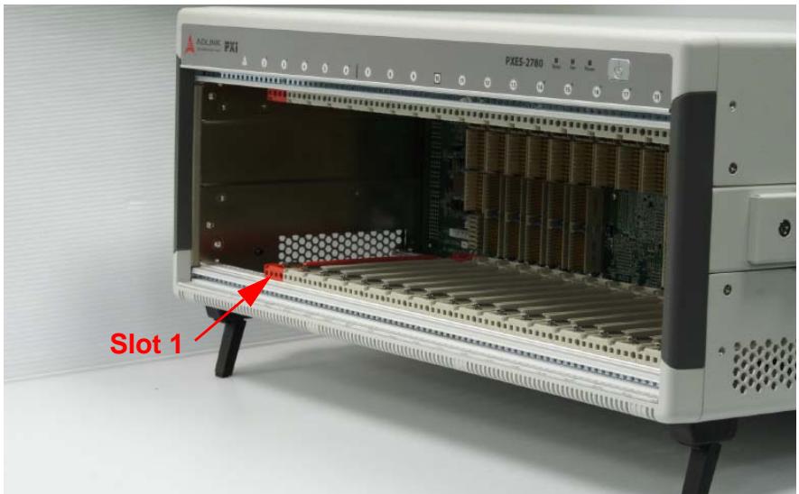
2. Locate the system controller slot (Slot 1, colored red).
![AOLINK FXI\nFXES-2780\nSlot 1](.pxes-2785-50-14013-1010-12/945b1a21fac092c074197179f5a1587165694ee89e5b59a3e6143bde3fccd38a.jpg)

Figure 2-1: System Controller Slot Location (Slot 1)

3. On the system controller module depress the module release latch.
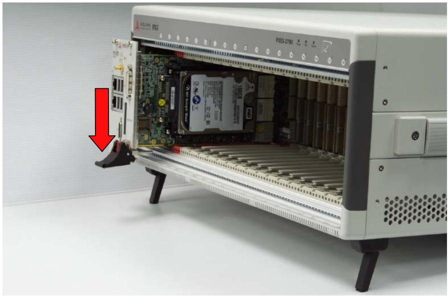
![Interior view of an electronic device showing internal circuit board and memory card, with a red arrow pointing to a component (no readable text or symbols)](.pxes-2785-50-14013-1010-12/5ff8f1688487dbdea1002a739c55091c682cf7a7d90ad76bbfcaf95b429ec85d.jpg)

Figure 2-2: Depress Module Release Latch

4. Align the system controller module’s top and bottom edges with the card guides, and carefully slide the module into the chassis.
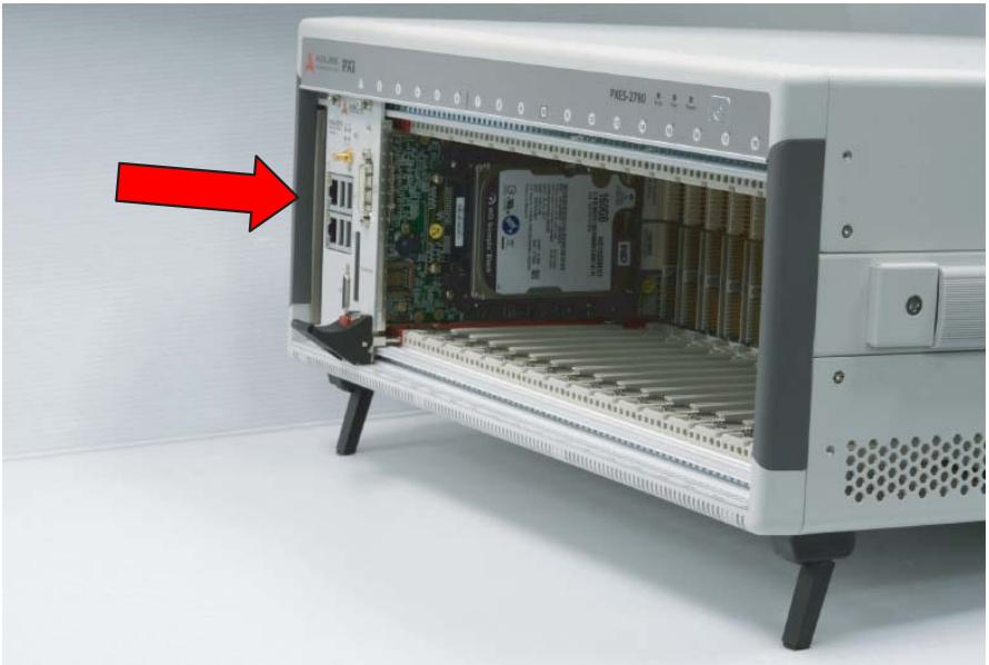
![Interior view of an Apple FXI internal processor showing internal circuit board and memory card (no readable text or symbols)](.pxes-2785-50-14013-1010-12/a5200ceafc002ca5712037b81c7f43ceb27d077d761392557c29488bcd7dcc30.jpg)

Figure 2-3: Align System Controller Module

5. Lift the system controller module latch until the module is securely seated in the chassis backplane
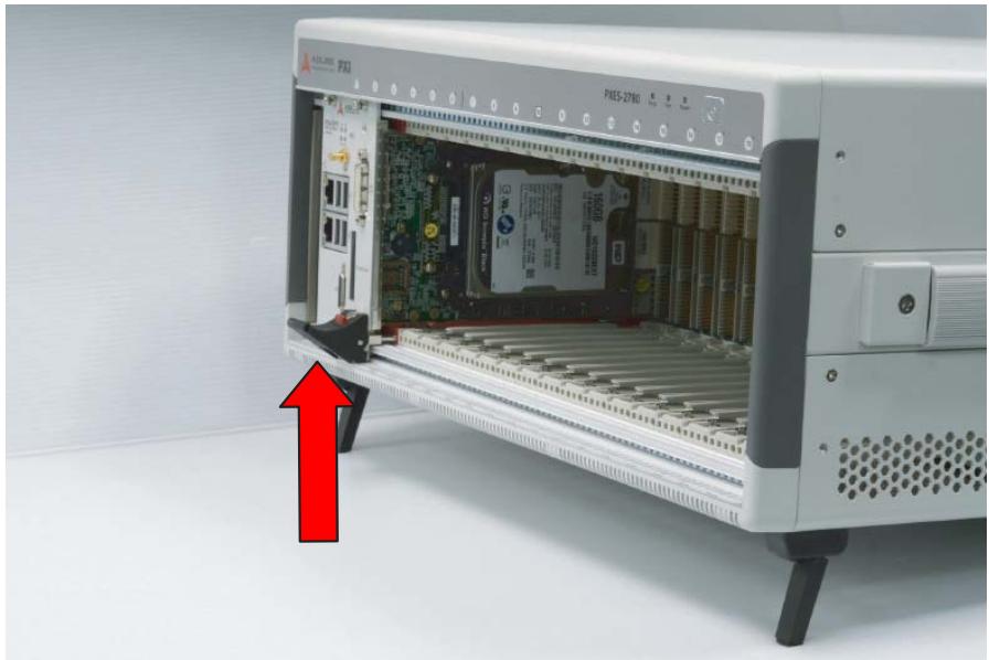
![Interior view of an Apple SIM-2780 PLC server with visible circuit board and memory card (no readable text or symbols)](.pxes-2785-50-14013-1010-12/4385984e67704b5bcb971951db9444e8732c04866ad2718d48c107961df1a55f.jpg)

Figure 2-4: Secure System Controller Module Latch

6. Fasten the screws on the module front panel, and connect all devices to the system controller.
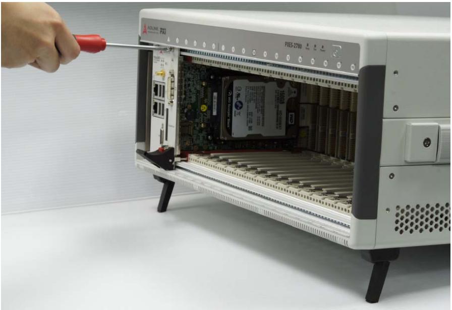
![Hand inserting a screwdriver into an open industrial rack-mounted device labeled 'PIES-2780' (no visible text or symbols on the device itself)](.pxes-2785-50-14013-1010-12/a75ce177a54341b52213007f508883b5b29852a89e9ed7c3cc79bb402531d410.jpg)

Figure 2-5: Fasten System Controller Module Screws

# 2.5.2 Installing Peripheral Modules

The PXE-2785 supports up to seventeen peripheral modules, including a system timing module. To install peripheral modules:

1. Select an available peripheral slot (2 to 18)
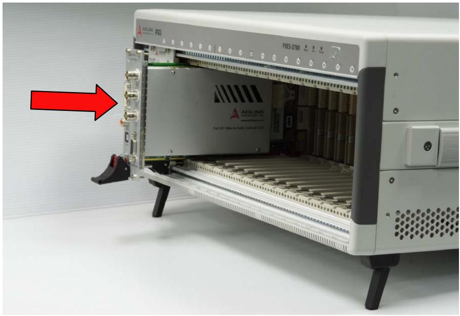
2. Depress the peripheral module’s latch and align the module’s top and bottom edges with the card guides.
3. Carefully slide the module into the chassis.
![ADLINK FXI\nFXES-2780\nADLINK\nFull HD Vias & Auto Cable Card](.pxes-2785-50-14013-1010-12/fb92b3ea03d0af1ea6715b53bfcef35dd6dd7b9f8350e3e92653e345833b99c9.jpg)

Figure 2-6: Insert Peripheral Module into Chassis

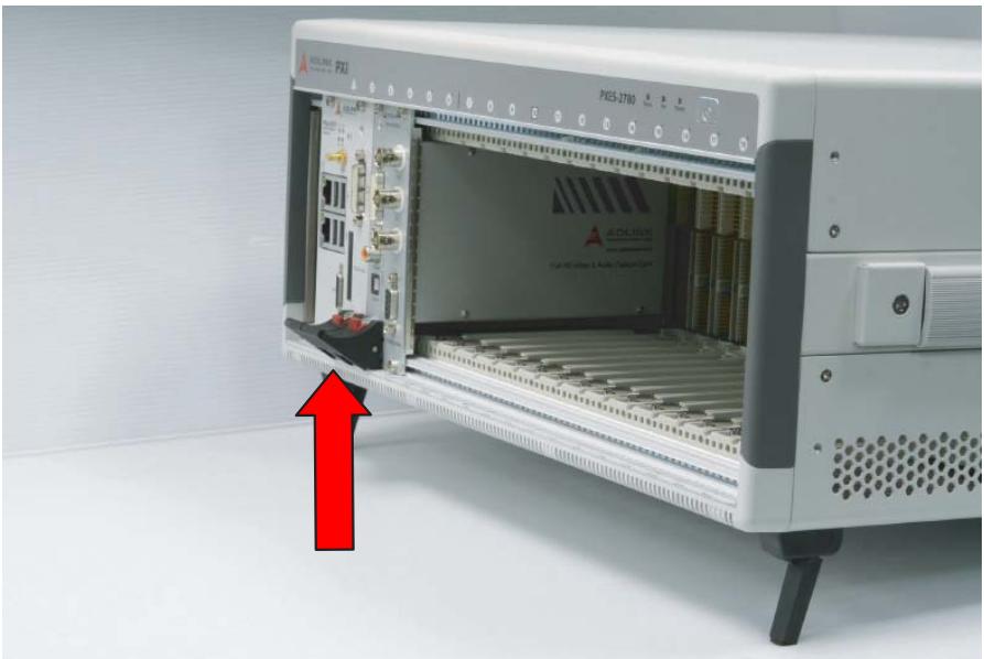
4. Lift the latch until the peripheral module is securely seated in the chassis backplane.
![Interior view of a connected industrial control unit (no visible text or symbols on the device body)](.pxes-2785-50-14013-1010-12/b879be33efab546a0a79ba64dc7a51aa4ce1cfcf2c514e48eaeed0906ff812a9.jpg)

Figure 2-7: Secure Peripheral Module Latch

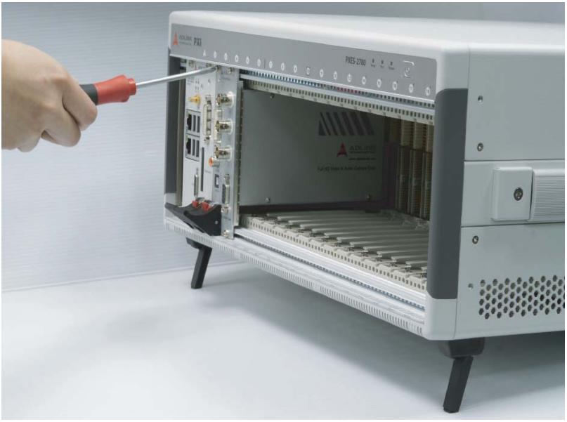
5. Fasten the screws on the module’s front panel.
![Close-up of a hand using a screwdriver to switch the internal components of an ADR-200 PLC power supply unit (no visible text or symbols on the device body)](.pxes-2785-50-14013-1010-12/d5f206a8605b0259592ff0a095719dc514bbe88e306b0f8b9787b8e0db5b7f89.jpg)

Figure 2-8: Fasten Peripheral Controller Module Screws

6. Repeat steps 1 to 5 to install additional PXI or PXIe peripheral modules.

![This image displays a white document icon with a folded top-right corner and a black border. Inside the document, there are several horizontal grey lines representing text. A large, bold red checkmark is superimposed over the center of the document.](.pxes-2785-50-14013-1010-12/966bc1adab185411cfbfaa14e5d9234deb253844f915acdb77ebf661d11ca4c0.jpg)
NOTE:

To improve efficiency of heat dissipation, after installing all PXI modules, please install filler plates for any unused slots.

# 2.6 Rack Mounting

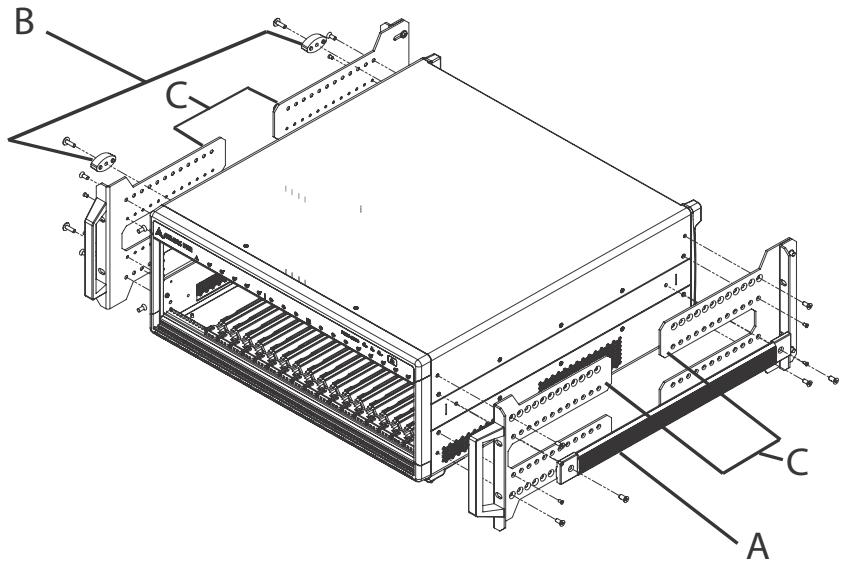
ADLINK provides hardware for optional installation of the PXES-2785 to a rack. When mounted in a rack, the Rack-Mount kit(G) (part number 3.91-95126-0010 PXES-2780) allows for adjustable placement of the PXES-2785 further back in the rack, thus allowing ample room at the front of the unit for external mechanical parts (such as cables and mass interconnect modules).
![B\nC\nA\nC](.pxes-2785-50-14013-1010-12/84421e36307684e211480dfda620d85852269c54d059e3455dc49592f825a037.jpg)

Figure 2-9: Rack Mount Assembly

<table><tr><td>Feature</td><td>Description</td></tr><tr><td>A</td><td>Carrying Handle</td></tr><tr><td>B</td><td>4 Rubber Feet (only 2 shown)</td></tr><tr><td>C</td><td>Mounting Brackets</td></tr></table>

Table 2-1: Rack Mount Assembly Legend

To rack mount the PXES chassis, follow the steps below:

1. Remove carrying handle from the chassis right side.
2. Remove the four rubber feet from the chassis left side. Store the feet for later use, as they will not be needed for rack mount use.
3. Install the mounting brackets on both sides of the chassis using the provided M4 screws. Position of the mounting brackets can be adjusted along the screw holes to position the chassis forward or backward as needed.
4. Install the chassis and kit into the rack using eight screws (not included).

# 2.6.1 Powering Up the System

The PXES-2785 is equipped with a 100 VAC to 240 VAC universal power supply unit requiring no input voltage selection.

![The image displays a standard safety warning sign. It features a red triangle with a white border containing a white exclamation point in the center. Below the triangle is a white rectangle with the word 'WARNING' printed in black, capital letters.](.pxes-2785-50-14013-1010-12/21d1db29dc46ba5d38ca704e5248da1699384a913940974d09721f01b81af2ca.jpg)

Do not to perform "hot swapping", replacement, disconnecting or connecting of any components (including cards and cabling) on chassis while the system is powered up. By not observing this Warning, system damage and/or data loss, and physical injury (due to possible shock hazard) may result.

To power up the system:

1. Connect one end of the supplied power cord to the power inlet located at the rear side of the chassis.
2. Plug the other end of the AC power cord to a properly grounded wall socket or power strip.
3. Press the power button. The Power LED (blue) lights up immediately.

# 2.7 PXES-2785 Software Resources

The following software resources are available for various application requirements.

# 2.7.1 ADLINK PXI Platform Services (APPS)

ADLINK PXI Platform Services is a software kit consisting of a utility and a group of software services and drivers.

#  ADLINK ChassisWatch

A GUI application program providing chassis status monitoring and configuration functions that are exclusive for ADLINK PXI Express chassis (PXES-2785, PXES-2780, PXES-2590, PXES-2301).

#  PXI Express Chassis Software Services

API services and drivers for the PXES-2785 defined in the PXISA PXI-6 Software Specification.

#  PXI Resource Manager

A Windows background service following the PXI-2 and PXI-6 Software Specification to scan PXI/PXIe controllers, chassis, and peripheral modules and generate PXI system description files accordingly.

#  PXI Trigger Management Software Services

API services and Trigger Manager defined in PXISA PXI-9 PXI and PXI Express Trigger Management Specification.

Please refer to the ADLINK PXI Platform Services user manual for more information.

# 2.7.2 MAPS Core DAQ Software & Utility

ADLINK’s MAPS Core DAQ Software & Utility (Measurement Automation and Platform Services) software package includes ADLINK DAQ drivers, device management utility (ACE), and PXI configuration settings utility. Please refer to the MAPS Core user manual for more information.

# 3 System Management & Configuration

The PXES-2785 chassis provides advanced system monitoring and control. Chassis conditions, including internal temperature, fan speed, and DC voltage can all be monitored via ADLINK ChassisWatch — a Windows based utility for ADLINK PXIe chassis monitoring and configuration.

Communication with the chassis monitoring control unit is available using an embedded controller, such as the ADLINK PXIe-3987, via ADLINK ChassisWatch to access the SMBus located on the system slot (1st slot), or, alternatively, using a remote PC to communicate via the LAN port (RJ-45 connector on the rear panel).

# 3.1 ChassisWatch

The PXES-2785 chassis provides advanced system monitoring and control via the ADLINK ChassisWatch GUI application. Related functions such as status monitoring, configurable PXI trigger bus bridges, and Smart Fan are introduced in the following sections. For more information about ChassisWatch, please refer to the ADLINK PXI Platform Services user manual.

![ChassisWatch Ver 3.1\nSelected Chassis\nChassis ID:2: PXES-2785\nTemp Unit\nCelsius\nRefresh\nStatus Refresh Rate\n1 sec\nChassis Status\nAC-DC PSU\nAC(V): 107.6\nAC(A): 1.3\nAC(W): 102.5\nT1(°C): 32.3\nT2(°C): 29.6\nT3(°C): 32.5\nF1(RPM): 5488\nF2(RPM): 5576\nDC Voltage (V)\n5Vsb: 5.083\n3.3V: 3.313\n5V: 5.068\n12V: 12.003\n-12V: -12.136\nFan Speed (RPM)\nF1: 1590\nF2: 1605\nF3: 1620\nSpeed Mode:\nAUTO\nVentilation Mode:\nNormal (38W)\nTemperature (°C)\nT1: 25.8\nT2: 25.7\nT3: 25.9\nT4: 26.0\nT5: 25.9\nT6: 26.3\nT7: 27.6\nT8: 26.3\nNetwork\nIP Address : 192.168.1.2 (Static IP)\nNetmask : 255.255.255.0\nIP GateWay : 192.168.1.1\nMAC Address : 00:88:11:22:FF:FF\nRef CLK PXI_CLK10\nClock Source: On Board\nLock Status: N/A\nTrigger Bus\nPXIE Link Routing\nFan Control\nAlarm Thresholds\nNetwork\nLog\nVersion Info\nCount=28\nLog Status\nChassis Data acquisition is underway](.pxes-2785-50-14013-1010-12/5b00dfb89252bbaf66cec35bee627141506342661ef22e1a3a93d94a05974c0a.jpg)

Figure 3-1: Chassis ChassisWatch GUI Application Utility

# 3.1.1 Chassis Status Monitor

Chassis conditions, including internal temperature, fan speed, and DC voltage can all be monitored by ChassisWatch running on an embedded PXI system controller or remote PC.

# 3.1.2 Software Configurable PXI Trigger Bus Bridges

The PXES-2785 provides software configurable trigger bus bridges, whereby the user can set the status of each trigger bus line as shown in Figure 3-2. Between trigger bus segments, TRIG BUS A (slot 1 to 6), B (slot 7 to 12), and C (slot 13 to 18), each PXI trigger bus line can be individually configured as different routing topologies. Trigger bus routing settings can be easily saved as templates and loaded quickly.

![ChassisWatch Ver 3.1\nTrigger Bus Current Setting\nTRIG BUS A	TRIG BUS B	TRIG BUS C\nPXI TRIG 0: ○———●	○———●	○\nPXI TRIG 1: ○———●	○———●	○\nPXI TRIG 2: ○———●	○———●	○\nPXI TRIG 3: ○———●	○———●	○\nPXI TRIG 4: ○———●	○———●	○\nPXI TRIG 5: ○———●	○———●	○\nPXI TRIG 6: ○———●	○———●	○\nPXI TRIG 7: ○———●	○———●	○\nNew Config\nApply Settings\nA--)B\n✓\nB--)C\n✓\nA--)B--)C\n✓\nA (--B\n✓\nB (--C\n✓\nA (--B (--C\n✓\nA (--B--)C\n✓\n(No Connect)\n✓\nOK\nSave As\nLoad\nReset All](.pxes-2785-50-14013-1010-12/f0b05b44f9c5334298b639219a7b9f910d82a0f1edc59c363e76bcfb5e22874f.jpg)

Figure 3-2: Trigger Bus Routing Settings

# 3.1.3 Smart Fan

When the Fan switch on the rear panel is set to AUTO, fans run at different speeds based on the measured temperature.

Target Temp indicates the temperature at which fans run at 100%. Using the default $5 0 ^ { \circ } \mathsf { C }$ as an example, fans run at 40% when all temperature readings are less than $\boldsymbol { 2 5 ^ { \circ } \mathrm { C } }$ , and begin ramp-up when any reading exceeds $\boldsymbol { 2 5 ^ { \circ } \mathrm { C } }$ .

Fans run at 100% speed if any temperature reading exceeds $5 0 ^ { \circ } \mathsf { C }$ (e.g., Target Temperature).

Setting parameters are as shown.

![| Highest temperature (°C) | Fan voltage duty cycle (%) |\n| ------------------------ | --------------------------- |\n| 0                        | 40                          |\n| 70                       | 100                         |](.pxes-2785-50-14013-1010-12/d448baeba15197266100a8f4c4b182d0b8190fed201d84cd0fb199155acc98f0.jpg)

Figure 3-3: Target Temperature Parameters

<table><tr><td>Mark</td><td>Temperature</td><td>Event</td></tr><tr><td>A</td><td>0°C / 32°F</td><td>Lowest chassis temperature at which fan speeds commence ramping up for final 25° temperature mark (see E)</td></tr><tr><td>B</td><td>45°C / 113°F</td><td>Highest chassis temperature at which fan speeds commence ramping up for final 70° temperature mark (see C)</td></tr><tr><td>C</td><td>70°C / 158°F</td><td>Highest chassis temperature at which fan speeds reach maximum speed</td></tr><tr><td>D</td><td>25°C to 70°C / 77°F to 158°F (temperature range)</td><td>Range over which maximum chassis temperature (at which fan speeds reach maximum speed) can be set</td></tr><tr><td>E</td><td>25°C / 77°F</td><td>Lowest chassis temperature at which fan speeds reach maximum speed</td></tr></table>

Table 3-1: Target Temperature Parameters Legend

# 3.2 Remote Management LAN Port

The remote management LAN port located at the rear of the chassis is connected to an embedded web service that is built into the PXES-2785. The webpage shows real-time chassis status.

![PXI Express Chassis Status Monitor\nNumber of page hits: 100\nVoltage (Uint V)\nDC 3.3V : 3.3\nDC 5V : 5.1\nDC 12V : 12.0\nDC -12V : -12.2\nDC 5Vsb : 5.1\n\nFan Speed (Uint RPM)\nFan 1 : 1650\nFan 2 : 1620\nFan 3 : 1650\n\nTemperature (Uint °C / °F)\nTemp Sensor 1 : 26.5 / 79.7\nTemp Sensor 2 : 27.2 / 81.0\nTemp Sensor 3 : 26.5 / 79.7\nTemp Sensor 4 : 26.3 / 79.3\nTemp Sensor 5 : 26.4 / 79.5\nTemp Sensor 6 : 26.9 / 80.4\nTemp Sensor 7 : 28.9 / 84.0\nTemp Sensor 8 : 28.7 / 83.7](.pxes-2785-50-14013-1010-12/35be56c09e92c7e3fbe4915203ad6762a33fff2985e56c172aadf0a746b51b32.jpg)

Figure 3-4: Chassis Status Monitor

<table><tr><td colspan="2">LAN Port Default IP Settings</td></tr><tr><td>Static IP Address</td><td>192.168.1.10</td></tr><tr><td>Netmask</td><td>255.255.255.0</td></tr></table>

Table 3-2: LAN Port Default IP Settings

The IP settings (DHCP/Static IP, IP address, netmask, gateway, and MAC address) can be set in ChassisWatch. For more information about ChassisWatch IP settings, please refer to the ADLINK PXI Platform Services user manual.

# Appendix A - Maintenance

This Appendix describes basic maintenance and troubleshooting instructions for the PXES-2785 chassis.

# A.1 Installation Problems

Inability to start the system frequently results from incorrect installation of the system controller, peripheral modules, and other components. Before starting the system, please ensure that:

 The system controller is properly installed and secured.
 All peripheral modules are properly seated on the slots.
All cables are properly connected to the system controller and peripheral modules.
 All installed peripheral modules are compatible for use in the chassis.
The power cord is securely plugged into the chassis power connector and power outlet/wall socket/power strip.

If the system fails to start when all installation conditions are met, remove all installed peripheral modules and try again. If the system starts normally, install one peripheral module at a time followed by powering up. You may also try installing the modules into different slots until the desired result is obtained.

# A.2 Basic Troubleshooting

<table><tr><td>Problem</td><td>Ensure that:</td></tr><tr><td>System fails to power up</td><td>► The power cord is securely plugged into the chassis power connector and wall socket/power strip► The wall socket/power strip is live► The power button on the chassis front panel is activated</td></tr><tr><td>No video output in the external display</td><td>► The external display is functioning properly► Display settings support external video.</td></tr><tr><td>Power LED (blue) is blinking</td><td>► There is no short circuit by removing all PXI modules (PXI controller and peripheral modules)If the signal persists, contact your dealer for further assistance</td></tr><tr><td>Fan LED (green) is blinking</td><td>► The fan is unobstructedIf the signal persists, contact your dealer for further assistance.</td></tr><tr><td>Temperature LED (amber) is blinking</td><td>► Airflow from the outlet apertures is unobstructed and steady; if not, ensure that adequate clearance for the intake apertures is providedIf the temperature of exhausted air is normal (70°C in Default setting) but the temperature LED is still blinking, contact your dealer for further assistance.</td></tr></table>

# A.3 Maintenance

# A.3.1 Handling the Chassis

The PXES-2785 is designed for both rack-mount and bench top use. When transporting or carrying the chassis, it is recommended that the handle be used, being designed to support the weight of the chassis for superior portability and balance.

The PXES-2785 weights 11.9 kg (26.2 lb). Please be careful when moving the chassis to avoid any possible injury.

# A.3.2 Cleaning the Exterior

Make sure that the system is turned off before cleaning the chassis exterior. Wipe the exterior with a clean cloth starting from areas that easily accumulate dust or dirt such as the area in and around the chassis and power supply air intake apertures.

# A.3.3 Power Requirements

Make sure that the power cord is in good condition before plugging it into the system. It is important to check the reliability of the power source. The PXES-2785 power supply is capable of handling 100 to 240 V AC within the 50 Hz to 60 Hz range. Do not connect the PXES-2785 to an already overloaded circuit.

# A.3.4 Replacing the Power Supply Module

The power supply module of PXES-2785 is with removable design that can be replaced in the field based on maintenance requirements. The power supply module can be ordered individually as backup part. Please contact your ADLINK sales window for more information.

Steps for replacing the power supply module:

1. Shut down PXES-2785.
2. Unplug AC power cord from the PXES-2785.
3. Remove 8 back panel screws as shown.
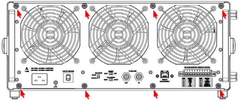
![Front view of a dual-flower industrial control panel with cooling fans and indicator lights (no text or symbols visible)](.pxes-2785-50-14013-1010-12/d04f377f3a142e8ae5956bd05eada6b63d72e5b0174c4da4112bf371f390b35d.jpg)

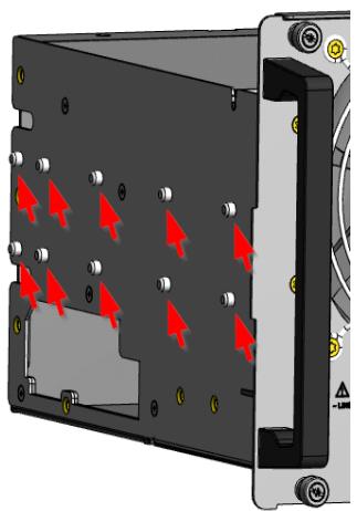
4. With the chassis housing firmly secured, carefully pull the two power supply module handles (at rear of chassis) outward to remove the power supply module.

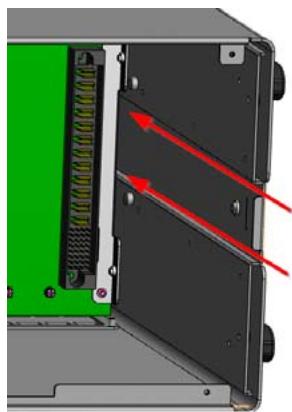
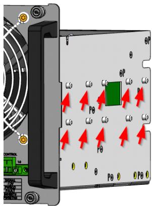
5. When inserting a power supply module, align the power supply module guide pins with the guide rails insides the chassis, and carefully slide the power supply module into the chassis.
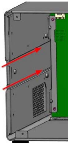
![3D diagram of a device rear panel with red and green directional arrows indicating movement or force (no text or symbols)](.pxes-2785-50-14013-1010-12/654d0bcfd7fa225807fda18630e6f9cda75dd2d4b03e6cf0bca8f52a2316f5ff.jpg)

![3D diagram of a black electronic device casing with red arrows indicating directional flow or movement, no text or symbols present.](.pxes-2785-50-14013-1010-12/e22f5ad1136d95e0134b05267cef134e61af0baff3f9930196d5630c3dc6901b.jpg)

![Close-up of a mechanical device showing internal components with red arrows indicating movement or force (no text or symbols visible)](.pxes-2785-50-14013-1010-12/928e51f1dc7617e8d28ae626b544bb068abe0d7cfdf3e82e8b5b126f0333ae24.jpg)

![OP\nOP\nP0\nP0\nP0\nP0\nP0\nCONTROL\n1.0\nC\nG\nC](.pxes-2785-50-14013-1010-12/a272222c2b556d3f6e3ca5ff6cf47ca8e7fa9eccb08626567c369a82dd22dcda.jpg)

6. Ensure the power module is fully inserted into the chassis.

7. Replace the 8 screws removed in Step 3 and reconnect the AC power cord.
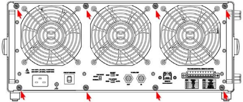
![Technical diagram of a front-mounted industrial control panel with three fans and labeled ports (no text or symbols present)](.pxes-2785-50-14013-1010-12/396e58839cb96e220b37263d3610e742faa415ca34f75402378bf7ad8a0dba38.jpg)

# Important Safety Instructions

For user safety, please read and follow all instructions, Warnings, Cautions, and Notes marked in this manual and on the associated device before handling/operating the device, to avoid injury or damage.

 Read these safety instructions carefully.
 Keep the User’s Manual for future reference.
Read the Specifications section of this manual for detailed information on the recommended operating environment.
 The device can be operated at an ambient temperature of 55ºC.
 For indoor use only.
 Altitude during operation: up to 2000m.
 Pollution degree: PD2.
 Equipment maintenance and service:

 Maintenance and inspection can only be performed by qualified and authorized technicians or personnel.
 Before performing maintenance tasks, it is imperative to turn off the power switch and remove the power cord from the unit to prevent possible electric shock leading to injury or death.

When installing/mounting or uninstalling/removing device, or when removal of a chassis cover is required for user servicing (See “Getting Started” on page 29.):

 Turn off power and unplug any power cords/cables.
 Reinstall all chassis covers before restoring power.

 To avoid electrical shock and/or damage to device:

 Keep device away from water or liquid sources.
 Keep device away from high heat or humidity.
 Keep device properly ventilated (do not block or cover ventilation openings).
 Always use recommended voltage and power source settings.
 Always install and operate device near an easily accessible electrical outlet.

 Secure the power cord (do not place any object on/over the power cord).
 Only install/attach and operate device on stable surfaces and/or recommended mountings.

 If the device will not be used for long periods of time, turn off and unplug it from its power source
 Never attempt to repair the device, which should only be serviced by qualified technical personnel using suitable tools
 A Lithium-type battery may be provided for uninterrupted backup or emergency power.

![The image displays a yellow triangular warning sign with a black border containing a black exclamation point in the center. Directly below the triangle is the text 'CAUTION:' printed in black capital letters.](.pxes-2785-50-14013-1010-12/41c29e7f4e81dbd9b8d216313aea8005dc76626c2dc9fbe153998ca31e9a2f03.jpg)

Risk of explosion if battery is replaced with one of an incorrect type; please dispose of used batteries appropriately.

Risque d’explosion si la pile est remplacée par une autre de type incorrect. Veuillez jeter les piles usagées de façon appropriée.

 The device must be serviced by authorized technicians when:

 The power cord or plug is damaged.
 Liquid has entered the device interior.
 The device has been exposed to high humidity and/or moisture.
 The device is not functioning or does not function according to the User’s Manual.
 The device has been dropped and/or damaged and/or shows obvious signs of breakage.

Disconnect the power supply cord before loosening the thumbscrews and always fasten the thumbscrews with a screwdriver before starting the system up.
 It is recommended that the device be installed only in a server room or computer room where access is:

 Restricted to qualified service personnel or users familiar with restrictions applied to the location, reasons therefor, and any precautions required.

 Only afforded by the use of a tool or lock and key, or other means of security, and controlled by the authority responsible for the location.

![Yellow triangular warning sign with black smoke symbol indicating hot weather](.pxes-2785-50-14013-1010-12/5f6970c7a7c6b5d56fed2c4c75114fb8034eb65a8bfd1c531864dc1aea6c638c.jpg)

# BURN HAZARD

Touching this surface could result in bodily injury. To reduce risk, allow the surface to cool before touching.

# Consignes de Sécurité Importante

S'il vous plaît prêter attention stricte à tous les avertissements et mises en garde figurant sur l'appareil , pour éviter des blessures ou des dommages.

 Lisez attentivement ces consignes de sécurité.
 Conservez le manuel de l'utilisateur pour référence future.
 Lisez la section Spécifications de ce manuel pour des informations détaillées sur l'environnement d'exploitation recommandé.
 L'appareil peut être utilisé à une température ambiante de 55 ° C.
 Pour une utilisation en intérieur uniquement.
 Altitude en fonctionnement: jusqu'à 2000m.
 Degré de pollution: PD2.
 Maintenance et entretien des équipements:

 L'entretien et l'inspection ne peuvent être effectués que par des techniciens ou du personnel qualifiés et autorisés.  Avant d'effectuer des tâches de maintenance, il est impératif de couper l'interrupteur d'alimentation et de retirer le cordon d'alimentation de l'appareil pour éviter tout choc électrique pouvant entraîner des blessures ou la mort.

 Lors de l'installation / du montage ou de la désinstallation / retrait du périphérique, ou lorsque le retrait d'un capot du châssis est requis pour la maintenance par l'utilisateur (See “Getting Started” on page 29.):

 Coupez l'alimentation et débranchez tous les cordons / câbles d'alimentation.

 Réinstallez tous les couvercles de châssis avant de rétablir l'alimentation.

 Pour éviter les chocs électriques et / ou les dommages à l'appareil:

 Gardez l'appareil éloigné de l'eau ou des sources de liquide.

 Gardez l'appareil éloigné de la chaleur ou de l'humidité élevée.
 Gardez l'appareil correctement ventilé (ne bloquez pas et ne couvrez pas les ouvertures de ventilation).
 Utilisez toujours les paramètres de tension et de source d'alimentation recommandés.
 Installez et utilisez toujours l'appareil à proximité d'une prise électrique facilement accessible.
 Fixez le cordon d'alimentation (ne placez aucun objet sur / sur le cordon d'alimentation).
 Installez / fixez et utilisez l'appareil uniquement sur des surfaces stables et / ou des supports recommandés.

 Si l'appareil n'est pas utilisé pendant de longues périodes, éteignez-le et débranchez-le de sa source d'alimentation
N'essayez jamais de réparer l'appareil, qui ne doit être entretenu que par du personnel technique qualifié à l'aide d'outils appropriés.
Une batterie de type lithium peut être fournie pour une alimentation de secours ou une alimentation de secours ininterrompue.

![The image displays a yellow triangular warning sign with a black border. Inside the triangle is a black exclamation point. Below the triangle, the text 'CAUTION:' is printed in black capital letters.](.pxes-2785-50-14013-1010-12/6c57e8ba4ed66bd26250eb504bae6269cd90f691180801c81615a23bbdc5e868.jpg)

Risque d’explosion si la pile est remplacée par une autre de type incorrect. Veuillez jeter les piles usagées de façon appropriée.

 L'appareil doit être réparé par des techniciens autorisés lorsque:

 Le cordon d'alimentation ou la fiche est endommagé.
 Du liquide a pénétré à l'intérieur de l'appareil.
 L'appareil a été exposé à une humidité et / ou une humidité élevées.
 L'appareil ne fonctionne pas ou ne fonctionne pas selon le manuel de l'utilisateur.
 L'appareil est tombé et / ou endommagé et / ou montre des signes évidents de casse.

Débranchez le cordon d'alimentation avant de desserrer les vis moletées et serrez toujours les vis moletées avec un tournevis avant de démarrer le système.

 Il est recommandé d'installer l'appareil uniquement dans une salle de serveurs ou une salle informatique où l'accès est:

 Réservé au personnel de maintenance qualifié ou aux utilisateurs familiers avec les restrictions appliquées à l'emplacement, les raisons de celles-ci et les précautions nécessaires.
 Seulement permis par l'utilisation d'un outil ou d'une serrure et d'une clé, ou d'autres moyens de sécurité, et contrôlé par l'autorité responsable de l'emplacement.

![Yellow triangular warning sign with black smoke symbol indicating hot weather](.pxes-2785-50-14013-1010-12/c4531c259ed28f802bef1e3960034eec6127f44a9030b2444b04917da75ad932.jpg)

# RISQUE DE BRÛLURES

Ne touchez pas cette surface, cela pourrait entraîner des blessures.

Pour éviter tout danger, laissez la surface refroidir avant de la toucher.

# Getting Service

Ask an Expert: http://askanexpert.adlinktech.com

# ADLINK Technology, Inc.

9F, No.166 Jian Yi Road, Zhonghe District

New Taipei City 235, Taiwan

Tel: +886-2-8226-5877

Fax: +886-2-8226-5717

Email: service@adlinktech.com

# Ampro ADLINK Technology, Inc.

5215 Hellyer Avenue, #110

San Jose, CA 95138, USA

Tel: +1-408-360-0200

Toll Free: +1-800-966-5200 (USA only)

Fax: +1-408-360-0222

Email: info@adlinktech.com

# ADLINK Technology (China) Co., Ltd.

300 Fang Chun Rd., Zhangjiang Hi-Tech Park

Pudong New Area, Shanghai, 201203 China

Tel: +86-21-5132-8988

Fax: +86-21-5132-3588

Email: market@adlinktech.com

# ADLINK Technology GmbH

Hans-Thoma-Straße 11

D-68163 Mannheim, Germany

Tel: +49-621-43214-0

Fax: +49-621 43214-30

Email: emea@adlinktech.com

Please visit the Contact page at www.adlinktech.com for information on how to contact the ADLINK regional office nearest you:
[🔗 Link to the original document](.pxes-2785-50-14013-1010-12/pxes-2785-50-14013-1010-12.pdf)