# PXIe-9908

# User’s Manual

8-Channel, 4-Quadrant

High-Density Source Measurement Unit (SMU) Module

![Exterior view of a ADLINK PXIe-9908 industrial control module with cooling fins and wiring (no readable text or symbols beyond branding)](.pxie-9908-50m-38010-1000-10/6aab328b017cac619637502d343e134046f1865af9588b5fa60df82659f8ab98.jpg)

Manual Rev.: 1.0

Revision Date: December 23, 2025

Part Number: 50M-38010-1000

# Preface

# Copyright

Copyright 2025 ADLINK Technology, Inc. This document contains proprietary information protected by copyright. All rights are reserved. No part of this manual may be reproduced by any mechanical, electronic, or other means in any form without prior written permission of the manufacturer.

# Disclaimer

The information in this document is subject to change without prior notice in order to improve reliability, design, and function and does not represent a commitment on the part of the manufacturer. In no event will the manufacturer be liable for direct, indirect, special, incidental, or consequential damages arising out of the use or inability to use the product or documentation, even if advised of the possibility of such damages.

# Environmental Responsibility

ADLINK is committed to fulfill its social responsibility to global environmental preservation through compliance with the European Union's Restriction of Hazardous Substances (RoHS) directive and Waste Electrical and Electronic Equipment (WEEE) directive. Environmental protection is a top priority for ADLINK. We have enforced measures to ensure that our products, manufacturing processes, components, and raw materials have as little impact on the environment as possible. When products are at their end of life, our customers are encouraged to dispose of them in accordance with the product disposal and/or recovery programs prescribed by their nation or company.

![Symbol of a trash bin crossed with two crossed lines and a solid rectangle below (no text or labels)](.pxie-9908-50m-38010-1000-10/7cee481812760c3d02dfc71121943cf7e06f0fc8f4d5600652ca815f238d26c0.jpg)

Battery Labels (for products with battery)

![Simple line drawing of a trash bin crossed out by two diagonal lines (no text or symbols)](.pxie-9908-50m-38010-1000-10/fa8fae40c6ab7200ed7041b81c7578e6111009b447ccfd00377abaca9f2c04ff.jpg)

![The image features a square outline containing the standard recycling symbol composed of three chasing arrows. Below the square is the text 'Li-ion'.](.pxie-9908-50m-38010-1000-10/fb1911aeff12f5e05aa0945cc30902863bc530a660357acc374159786561a9ff.jpg)

![RECYCLF\nRBRC\nLi-ion\n1.800.822.8837](.pxie-9908-50m-38010-1000-10/a7432f9eb4b052b59f74ecf0b53d07b8c7c2f8374cfbd4df3b07f1e411bf8f8c.jpg)

![廢電池請回收](.pxie-9908-50m-38010-1000-10/2dc6b13598565e9da9794cc864014f8379d152dc2c4fd6020a24b9bc7cc728ae.jpg)

# California Proposition 65 Warning

![A yellow triangular warning sign with a thick black border containing a black exclamation mark in the center.](.pxie-9908-50m-38010-1000-10/6d93c792dff97ae8156e83574e8649e069bfda526beb9e430ef572b4a3d2d24a.jpg)

WARNING: This product can expose you to chemicals including acrylamide, arsenic, benzene, cadmium, Tris(1,3-dichloro-2-propyl)phosphate (TDCPP), 1,4-Dioxane, formaldehyde, lead, DEHP, styrene, DINP, BBP, PVC, and vinyl materials, which are known to the State of California to cause cancer, and acrylamide, benzene, cadmium, lead, mercury, phthalates, toluene, DEHP, DIDP, DnHP,

DBP, BBP, PVC, and vinyl materials, which are known to the State of California to cause birth defects or other reproductive harm. For more information go to www.P65Warnings.ca.gov.

# Trademarks

Product names mentioned herein are used for identification purposes only and may be trademarks and/or registered trademarks of their respective companies.

# Conventions

Take note of the following conventions used throughout this manual to make sure that users perform certain tasks and instructions properly.

![The image features a white document icon with a folded upper-left corner. Faint horizontal gray lines run across the white area, resembling lines of text. A large, thick red checkmark is overlaid diagonally across the center, slanting upward from left to right. The entire graphic is enclosed within a thin black border.](.pxie-9908-50m-38010-1000-10/5fc53dfd54af055522bd9a06790eb724603cbed6aea2f04efb2e030b33058194.jpg)
NOTE:

Additional information, aids, and tips that help users perform tasks.

![A yellow triangular warning sign with a black border featuring a large black exclamation point in the center.](.pxie-9908-50m-38010-1000-10/cf82611df4a9e05adad1231d43037720c2418fd8f0eab43380cd89c712bc4eba.jpg)
CAUTION:

Information to prevent minor physical injury, component damage, data loss, and/or program corruption when trying to complete a task.

ATTENTION: Informations destinées à prévenir les blessures corporelles mineures, les dommages aux composants, la perte de données et/ou la corruption de programme lors de l'exécu- tion d'une tâche.

![The image displays a standard warning symbol consisting of a red isosceles triangle with rounded corners. Inside the red triangle, there is a large white exclamation mark centered in the middle. The background outside the triangle is white.](.pxie-9908-50m-38010-1000-10/08e5fb2b573dc0428cede26c142ab02fd67d2a5a4ab2ddaf7c1d0a5af8b64bf3.jpg)
WARNING:

Information to prevent serious physical injury, component damage, data loss, and/or program corruption when trying to complete a specific task.

AVERTISSEMENT: Informations destinées à prévenir les bles- sures corporelles graves, les dommages aux composants, la perte de données et/ou la corruption de programme lors de l'exécution d'une tâche spécifique.

Revision History

<table><tr><td>Revision</td><td>Description</td><td>Date</td><td>By</td></tr><tr><td>1.0</td><td>Initial release</td><td>2025-12-23</td><td>AL</td></tr></table>

# Table of Contents

Preface...

List of Figures ....

List of Tables...... ..vi

1 Introduction....

1.1 Features...

1.2 Applications .

1.3 PXIe-9908 System Components .. 2

2 Specifications ...

2.1 Quadrant Diagram ..... .5

2.2 Device capabilities . .6

2.3 Supplemental Specifications . .6

2.4 Additional Specifications . 7

2.5 Accuracy.. 7

3 Mechanical Layout ...............

3.1 Mechanical Dimensions . .9

4 Connector Pinouts .. .11

4.1 Pin Assignments . .11

5 Getting Started... .13

5.1 Package Contents.. ..13

5.2 Unpacking.. ..13

5.3 Installation.. .13

6 Driver Installation and Software Support .. ..15

6.1 Driver Installation ... ..15

6.2 Software Support .. .15

Safety Instructions......... .17

Getting Service............ .19

# List of Figures

Figure 1: Quadrant diagram.. 5
Figure 2: Cascade mode diagram . 5
Figure 3: Dual-slot PCB dimensions.. .9
Figure 4: Single-slot PCB dimensions .. .10
Figure 5: CN1 pin assignments . .11

# List of Tables

Table 1: CN1 pin assignment legend.. .11

# 1 Introduction

The PXIe-9908 is an 8-channel, 4-quadrant, high-density source measurement unit (SMU) module featuring integrated remote (4-wire) sensing, designed for automated testing and mini/microLED wafer probing applications. It supports precision sourcing and measurement up to ±100 V and 100 mA, with scalable configurations. With compatibility across major operating systems and programming languages, it delivers fast, accurate, and reliable testing performance tailored for automated test systems and next-generation display technologies.

# 1.1 Features

The PXIe-9908 is a high-precision system source measure unit (SMU) with following features:

Voltage range:

o -10 V to 20 V
o -30 V to 30 V in cascade mode
o -100 V to 100V (measurement only, in the 10 μA current range)

• Current ranges:
o 100mA, 10mA, 2mA, 200uA, 40μA, 10μA, 5μA, 1μA, 100nA
High-speed sampling rate
o Up to 1MS/s maximum measurement sampling rate per channel
High-speed updating rate
o Up to 100KHz maximum update rate per channel
4-wire remote sensing and guarding

# 1.2 Applications

Automated Test Equipment (ATE)

Mini/micro LED wafer probing

Laboratory automation

Industrial process control and monitoring

IC testing

# 1.3 PXIe-9908 System Components

<table><tr><td>Component</td><td>Description</td></tr><tr><td>PXle chassis&lt;img src="images/8c3bb92519a3e9612b6993813cd01c58aac7c68e6592ece741e0e15e3a62a45c.jpg"/&gt;</td><td>The PXle or hybrid chassis hosts the PXle-9908, providing the power, communication, and timing support required for its operation.</td></tr><tr><td>PXle controller&lt;img src="images/e609562d42e978632147cd7fd541fb92bb8c468b026bad8174457049e9c11031.jpg"/&gt;</td><td>The PXle controller is used as a host PC to control the peripheral device, the PXle-9908. This component is installed in the same PXle chassis as the PXle-9908.</td></tr><tr><td>Remote controller&lt;img src="images/5750f0a93d47394967e979e43232d7a1a62e01bb4988cd1ebe797ece0077700e.jpg"/&gt;</td><td>You can also use a PXle remote controller to control the PXle-9908 from a host PC. This component is installed in the same PXle chassis as the PXle-9908.</td></tr></table>

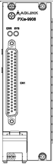
![ADLINK\nPXIe-9908\nERR SYS\nCN1](.pxie-9908-50m-38010-1000-10/6602b04002c0e2e0334a8a32d0cbcf16495e760111088eff6324e438ab322d10.jpg)

![Technical diagram showing two connected VGA connectors with a close-up of the internal I/O port (no text or labels visible)](.pxie-9908-50m-38010-1000-10/114dd5b06fc382899bedbd0ae131d30d15c28ad7a2efb0144ba4e13c25a6bb88.jpg)

Cables and Accessories

![Close-up of a server rack unit with multiple ports and connectors (no visible text or labels)](.pxie-9908-50m-38010-1000-10/5f1d4acfa8d6a04bf8b80be09f007783c4a84c20601b86a603693a13343f72b6.jpg)

Driver and Application
![This diagram illustrates a layered software architecture for device management and runtime. The text is organized into three main areas: a left-hand management column, three right-hand application columns, and a bottom runtime layer.\n\n**Left Column (MAPS Core Management):**\n*   **MAPS Core**\n*   **Device Management**\n*   **Device Manager (ACE)**\n*   **PXI Platform Resource Mgmt. Utility**\n*   **PXI Platform ChassisWatch Utility**\n*   **DAQ/IO Module Function Test Utility**\n\n**Right Columns (User Applications and SDKs):**\nThree vertical stacks represent different programming environments:\n1.  **C/C++ Stack:**\n    *   **User APPs in C/C++**\n    *   **MAPS/C C/C++ SDK for DAQ/IO module**\n2.  **LabVIEW Stack:**\n    *   **User APPs in LabVIEW**\n    *   **MAPS/LV LabVIEW SDK for DAQ/IO module**\n3.  **C# Stack:**\n    *   **User APPs in C#**\n    *   **MAPS/C# C# SDK for DAQ/IO module Coming soon**\n\n**Bottom Layer (Runtime):**\nA dark grey footer spans the width of the diagram:\n*   **MAPS Core -Device Runtime**\n*   **PXI Platform Service**\n*   **DAQ/IO Module Device Driver**\n*   **DAQ/IO Module Runtime Library**\n\n**Connections:**\n*   The diagram implies a vertical hierarchy where **User APPs** interact with their respective **SDK** blocks below them.\n*   The **SDK** blocks (MAPS/C, MAPS/LV, MAPS/C#) sit directly above the bottom **Runtime** layer, indicating they utilize the 'DAQ/IO Module Device Driver' and 'Runtime Library.'\n*   The left **Device Management** column runs parallel to the SDK layers, suggesting it oversees the system resources and utilities.](.pxie-9908-50m-38010-1000-10/e9b27937055dbb98cecca6d2d50b2638b4566a033ea580ab032cd54c0e18962d.jpg)

The SMU instrument.

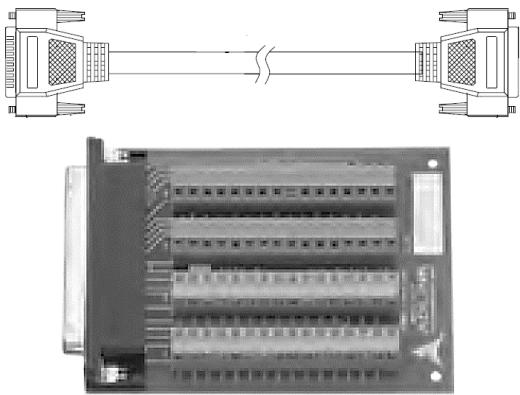
Cables and accessories provide connectivity to and from your instrument for measurements.

Cable: ACL-10262-1

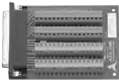
Terminal: TB-6221

Termination Board with 62-pin D-Sub Connector (cables not included)

ACL-10262\*1

D-Sub 62 Pin (Male) to D-Sub 62 Pin (Female), 1M

Note: Using TB-6221 and ACL-10262 may cause unstable output and measurements when operating in the low current range (below 2 mA). If operation in this low current range is required, it is recommended to design dedicated cables and connection boards.

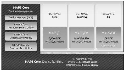
ADLINK provides MAPS/SMU SDK, an all-in-one software solution that includes drivers, device management, utilities, and examples.

Platform:

\- Windows 10/11 (64-bit)

Supported programming language:

\- C++

\- LabVIEW

This page intentionally left blank.

# 2 Specifications

Specifications are valid under the following conditions unless otherwise noted.

Ambient temperature: $2 5 ^ { \circ } \mathsf C \pm 5 ^ { \circ } \mathsf C$
Calibration interval: 1 year
Warm-up time: 30 minutes
• Fans set to the highest setting when the PXI Express chassis offers multiple fan speed settings

# 2.1 Quadrant Diagram
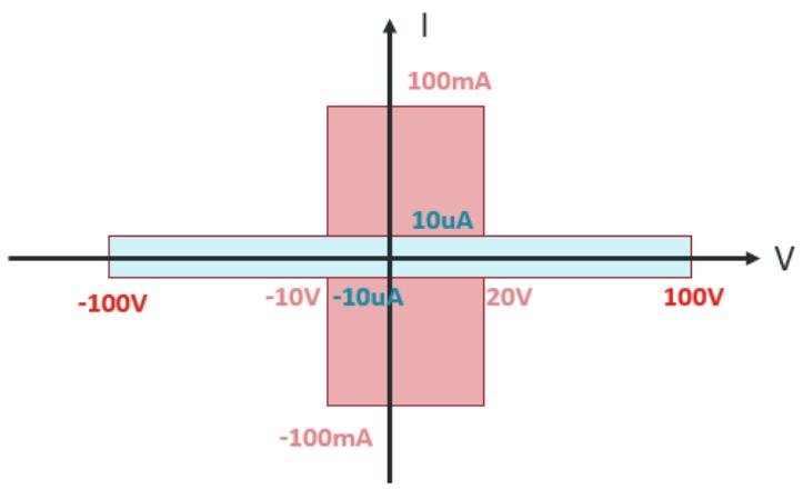
![| Voltage | Current (mA) |\n| ------- | ------------ |\n| -100V   | 100          |\n| -10V    | 10           |\n| 20V     | 1            |\n| 100V    | 1            |](.pxie-9908-50m-38010-1000-10/40218bc1034d9fa2481a22cb33229ff1e0ace4192b6870e9198bb3dd2cf87217.jpg)

Figure 1: Quadrant diagram

Cascade mode
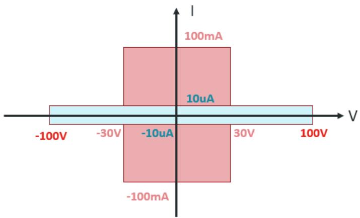
![| Voltage (V) | Current (mA) |\n|-------------|--------------|\n| -100V       | 100          |\n| -30V        | 10           |\n| -10uA       | 1            |\n| 30V         | 1            |\n| 100V        | 1            |](.pxie-9908-50m-38010-1000-10/25574426628e35ba445f433d50142149a5a4d60d5c918a7046fffba49a11dec5.jpg)

Figure 2: Cascade mode diagram

2.2 Device capabilities

<table><tr><td>Channels</td><td>8 channels</td></tr><tr><td>Power Output</td><td>Single channel: 2 W max8 channels: 16 W max</td></tr><tr><td>Voltage Source Range</td><td>-10 to +20V</td></tr><tr><td>Voltage Measure Range</td><td>-10 to +20V</td></tr><tr><td>Current Source Range</td><td>100mA, 10mA, 2mA</td></tr><tr><td></td><td>200 μA, 40 μA, 5 μA, 1 μA</td></tr><tr><td></td><td>100nA</td></tr><tr><td>Current Measure Range</td><td>100mA, 10mA, 2mA</td></tr><tr><td></td><td>200 μA, 40 μA, 5 μA, 1 μA</td></tr><tr><td></td><td>100nA</td></tr><tr><td colspan="2"></td></tr><tr><td>Voltage Measure Range</td><td>±100V</td></tr><tr><td>Current Source Range</td><td>10 μA</td></tr><tr><td>Current Measure Range</td><td>10 μA</td></tr></table>

2.2.1 Cascade Mode

<table><tr><td>Channels</td><td>4 channels</td></tr><tr><td>Power Output</td><td>Single channel: 3 W max.4 channels: 12 W max.</td></tr><tr><td>Voltage Source Range</td><td>±30V</td></tr><tr><td>Voltage Measure Range</td><td>±30V</td></tr><tr><td>Current Source Range</td><td>100mA, 10mA, 2mA</td></tr><tr><td></td><td>200 μA, 40 μA, 5 μA, 1 μA</td></tr><tr><td></td><td>100nA</td></tr><tr><td>Current Measure Range</td><td>100mA, 10mA, 2mA</td></tr><tr><td></td><td>200 μA, 40 μA, 5 μA, 1 μA</td></tr><tr><td></td><td>100nA</td></tr><tr><td colspan="2"></td></tr><tr><td>Voltage Measure Range</td><td>±100V</td></tr><tr><td>Current Source Range</td><td>10 μA</td></tr><tr><td>Current Measure Range</td><td>10 μA</td></tr></table>

2.3 Supplemental Specifications

<table><tr><td>Resolution</td><td>18-bit</td></tr><tr><td>Max Measure Rate</td><td>1M SPS</td></tr><tr><td>Max Source Update Rate</td><td>100K SPS</td></tr><tr><td>Source Event Delay</td><td>5μs</td></tr><tr><td>Input Triggers</td><td>Start</td></tr><tr><td></td><td>Source</td></tr><tr><td></td><td>Sequence Advance</td></tr><tr><td></td><td>Measure</td></tr><tr><td>Output Triggers</td><td>Source Complete</td></tr><tr><td></td><td>Sequence Iteration Complete</td></tr><tr><td></td><td>Sequence Engine Done</td></tr><tr><td></td><td>Measure Complete</td></tr></table>

2.4 Additional Specifications

<table><tr><td>Dimensions (L x W x H)</td><td>209.9 mm × 40.3 mm × 130.6 mm, dual-slot209.9 mm × 20 mm ×130.6 mm, single-slot</td></tr><tr><td>Front Panel Connector</td><td>62-position D-SUB, female</td></tr><tr><td>Power Consumption</td><td>Typical: 3.3V/2.804mA12V/1280.22mA</td></tr><tr><td></td><td>Max: 3.3V/2.814mA12V/4225.45mA</td></tr><tr><td>Operating Temperature</td><td>0°C to 50°C</td></tr><tr><td>Storage Temperature</td><td>-20°C to 70°C</td></tr><tr><td>Operating Humidity</td><td>10% to 90%, non-condensing</td></tr><tr><td>Storage Humidity</td><td>5% to 95%, non-condensing</td></tr><tr><td>Certificate</td><td>CE EN 55032/ 55035</td></tr><tr><td></td><td>FCC Part 15B</td></tr></table>

2.5 Accuracy

<table><tr><td>Voltage rage</td><td>Source Accuracy</td><td>Sink Accuracy</td></tr><tr><td>-10 to +20V</td><td>0.02% ± 2mV</td><td>0.02% ± 2mV</td></tr><tr><td>±30V</td><td>0.02% ± 2mV</td><td>0.02% ± 2mV</td></tr><tr><td>±100V</td><td></td><td>0.02% ± 15mV</td></tr></table>

<table><tr><td>Current rage</td><td>Source Accuracy</td><td>Sink Accuracy</td></tr><tr><td>100mA</td><td>0.05% ± 20μA</td><td>0.05% ± 20μA</td></tr><tr><td>10mA</td><td>0.05% ± 2μA</td><td>0.05% ± 2μA</td></tr><tr><td>2mA</td><td>0.05% ± 500nA</td><td>0.05% ± 500nA</td></tr><tr><td>200uA</td><td>0.05% ± 50nA</td><td>0.05% ± 50nA</td></tr><tr><td>40uA</td><td>0.05% ± 10nA</td><td>0.05% ± 10nA</td></tr><tr><td>5uA</td><td>0.05% ± 3nA</td><td>0.05% ± 3nA</td></tr><tr><td>1uA</td><td>0.05% ± 300pA</td><td>0.05% ± 300pA</td></tr><tr><td>100nA</td><td>0.1% ± 100pA</td><td>0.1% ± 100pA</td></tr></table>

This page intentionally left blank.

# 3 Mechanical Layout

# 3.1 Mechanical Dimensions

# 3.1.1 Dual-Slot PCB Dimensions

![This image is a technical engineering drawing of a hardware module, specifically an ADLINK PXIe-9906, shown in three views with dimensional annotations.\n\n**Top Left View (Front Panel):**\n*   **Dimensions:** '40.30' (width), '130.62' (total height), '128.70' (height of main bracket), '122.50' (height of connector area).\n*   **Text:** 'ADLINK', 'PXIe-9906', 'ERR', 'SYS', 'CN1'.\n\n**Top Right View (Side Profile):**\n*   **Dimensions:** '100' (height), '209.93' (total length).\n\n**Bottom View (PCB Underside):**\n*   Shows the bottom side of the printed circuit board with various component footprints. There is no legible text or dimensions visible in this section.](.pxie-9908-50m-38010-1000-10/3f2429d6c973b784c881b84ef37326d1a493ca6b41e18ea88e3a8638392197e6.jpg)
Figure 3: Dual-slot PCB dimensions

# 3.1.2 Single-Slot PCB Dimensions

![The image displays technical line drawings of an ADLINK PXIe-9908 device from three angles.\n\n**Top Left View:**\n*   Shows the front I/O bracket.\n*   Vertical dimensions listed are **130.63**, **128.70**, and **122.50**.\n*   Horizontal dimension at the top is **20**.\n*   Text on the faceplate reads **ADLINK**, **PXIe-9908**, **ERR**, **SYS**, and **CN1**.\n\n**Top Right View:**\n*   Shows the top of the device casing.\n*   Horizontal dimension at the bottom is **209.93**.\n*   Vertical dimension on the right is **100**.\n*   The logo and text **ADLINK TECHNOLOGY INC.** are visible on the casing.\n\n**Bottom View:**\n*   Shows the underside circuit board with various component outlines and mounting holes.](.pxie-9908-50m-38010-1000-10/a858f2d1c1b48bbd3652a5ae1c3031f3abb71d614790931f599fa4d16c08aa2b.jpg)
Figure 4: Single-slot PCB dimensions

# 4 Connector Pinouts

# 4.1 Pin Assignments

The PXIe-9908 comes equipped with one 62-pin D-Sub Male connector, CN1. CN1 is located on the faceplate and is used for sensing, output, guard, and calibration signals. The pin assignments are illustrated in the figure below.

CN1
![| Level | Channel | Value |\n|---|---|---|\n| CH0 Output HI | CH0 Sense HI | 22 |\n| CH0 Output HI | CH0 Sense LO | 43 |\n| NC | CH0 Guard | 23 |\n| NC | CH1 Sense LO | 44 |\n| CH1 Output HI | CH1 Sense LO | 45 |\n| CH1 Output HI | CH1 Output LO | 46 |\n| CH1 Sense HI | CH1 Guard | 25 |\n| CH1 Sense HI | CH1 Guard | 46 |\n| NC | NC | 26 |\n| NC | CH2 Sense LO | 47 |\n| NC | CH2 Sense LO | 48 |\n| CH2 Sense HI | CH2 Sense LO | 48 |\n| CH2 Sense HI | CH2 Guard | 49 |\n| CH2 Output HI | CH2 Guard | 49 |\n| NC | NC | 29 |\n| NC | CH3 Sense LO | 50 |\n| NC | CH3 Sense LO | 51 |\n| CH3 Output HI | CH3 Guard | 51 |\n| CH3 Output HI | CH3 Sense LO | 52 |\n| CH3 Sense HI | CH3 Sense LO | 52 |\n| NC | NC | 32 |\n| NC | CH4 Sense LO | 53 |\n| NC | CH4 Sense LO | 54 |\n| CH4 Sense HI | CH4 Guard | 54 |\n| CH4 Sense HI | CH4 Sense LO | 55 |\n| CH4 Output HI | CH4 Guard | 55 |\n| CH4 Output HI | CH4 Sense LO | 56 |\n| NC | NC | 35 |\n| NC | CH5 Sense LO | 57 |\n| NC | CH5 Sense LO | 58 |\n| NC | NC | 38 |\n| NC | CH6 Sense LO | 59 |\n| NC | CH6 Sense LO | 60 |\n| CH6 Sense HI | CH6 Sense LO | 60 |\n| CH6 Sense HI | CH6 Guard | 61 |\n| CH6 Output HI | CH6 Guard | 61 |\n| CH6 Output HI | CH7 Sense LO | 61 |\n| NC | CH7 Sense LO | 62 |\n| NC | CH7 Sense LO | 62 |\n| NC | CH7 Sense LO | 62 |\n| NC | CH7 Sense LO | 62 |\n| NC | CH7 Sense LO | 62 |\n| NC | CH7 Sense LO | 62 |\n| NC | CH7 Sense LO | 62 |\n| NC | CH7 Sense LO | 62 |\n| NC | CH7 Sense LO | 62 |\n| NC - AHI Source: EN_100V\n    AGND: CH4 Output LO\n    AGND: CH5 Output LO\n    AGND: CH6 Output LO\n    AGND: CH7 Output LO\n    AHI Source: EN_100V Source\n    AHI Source: CH4 Output LO\n    AHI Source: AGND\n    AHI Source: CH5 Output LO\n    AHI Source: AGND\n    AHI Source: CH7 Output LO\n    AHI Source: CH7 Guard](.pxie-9908-50m-38010-1000-10/3930540cb46efeaab243f68d993844db6954655d7ea05b3a4a4db263c4147017.jpg)

Figure 5: CN1 pin assignments

Table 1: CN1 pin assignment legend

<table><tr><td>Signal Name</td><td>I/O</td><td>Description</td></tr><tr><td>CH&lt;0...7&gt; Output HI</td><td>O</td><td>The primary sourcing terminal (positive) for voltage or current.</td></tr><tr><td>CH&lt;0...7&gt; Output LO</td><td>O</td><td>The return terminal (negative) of the source output.</td></tr><tr><td>CH&lt;0...7&gt; Sense HI</td><td>I</td><td>The positive remote sensing terminal.</td></tr><tr><td>CH&lt;0...7&gt; Sense LO</td><td>I</td><td>The negative remote sensing terminal.</td></tr><tr><td>CH&lt;0...7&gt; Guard</td><td>O</td><td>A driven shield terminal used to reduce leakage current and improve low-level measurement accuracy.</td></tr><tr><td>En_100V</td><td>I</td><td>Enable +-100V measurement</td></tr><tr><td>En_100V Source</td><td>O</td><td>Connect to En_100V if need to enable +-100V measurement or leave it unconnected.</td></tr><tr><td>Cal HI/ Cal LO/ Cal sense HI/ Cal sense LO</td><td>I/O</td><td>For external calibration use only, otherwise leave unconnected.</td></tr><tr><td>NC</td><td></td><td>No connect</td></tr></table>

This page intentionally left blank.

# 5 Getting Started

# 5.1 Package Contents

PXIe-9908
Product Warranty Card

# 5.2 Unpacking

The card contains electrostatic-sensitive components that can be easily damaged by static electricity. Therefore, it should be handled on a grounded anti-static mat. The operator must wear an anti-static wristband grounded at the same point as the mat.

Inspect the card module carton for visible damage. Shipping and handling may cause damage to your module, so ensure there are no signs of damage before proceeding.

After opening the carton, carefully remove the system module and place it only on a grounded anti-static surface with the component side up. Inspect the module again for any damage. Press down on all socketed ICs to ensure they are properly seated. This should be done only with the module on a firm, flat surface.

![The image features a square icon depicting a white document with a folded top-left corner. Faint horizontal lines run across the page, suggesting text. A large, bold red checkmark is superimposed diagonally over the center of the document. The entire graphic is enclosed within a thin black border.](.pxie-9908-50m-38010-1000-10/cf0b33c970b0a04b8f038d474edcdc3ee1030729ca0ea585c0d7b97703caafb8.jpg)
NOTE:

Please DO NOT attempt to install a damaged board in the computer.

# 5.3 Installation

# 5.3.1 Device Installation Procedure

1. Verify that the chassis is connected to an AC power source before installing the module. The AC power cord provides proper grounding and protects the chassis from electrical hazards during installation.
2. Turn off the chassis before proceeding with any installation steps.
3. Inspect the slot pins on the chassis backplane for any signs of bending or damage. Do not install the module if any damage is present.
4. Ensure that the chassis inlet and outlet vents are unobstructed.
5. Remove the black plastic caps from all captive screws on the module’s front panel.
6. Locate a supported slot in the chassis. The PXIe-9908 can be installed in PXI Express hybrid peripheral slots or PXI Express peripheral slots.
7. Discharge any static electricity by touching an unpainted metal surface on the chassis.
8. Confirm that the ejector handle is in the unlatched position.
9. Align the module with the upper and lower card guides and carefully slide it into the selected slot until fully seated.
10. Latch the module by lifting the ejector handle upward.
11. Install filler panels or slot blockers in any unused slots to maintain proper airflow and EMC performance.

This page intentionally left blank.

# 6 Driver Installation and Software Support

# 6.1 Driver Installation

Download the drivers for your system from the PXIe-9908 product page at:

https://www.adlinktech.com.cn/products/pxi\_pxie\_platform/pxi\_pxie\_modules/pxie-9908

1. Download SMU\_SDK from the driver section on the PXIe-9908 product page on the ADLINK website.
2. Double-click the installation file.
3. Follow the instructions until the installation procedure is complete.

# 6.2 Software Support

ADLINK provides versatile software drivers and packages to suit various user approaches to building a system. In addition to programming libraries, such as DLLs for most Windows-based systems, ADLINK also provides drivers for other application environments, such as LabVIEW. ADLINK Measurement, Automation & Platform Service (MAPS) is a software service package designed for data acquisition, automation, and PXI platforms. By leveraging low-level kernel management and a user-friendly API, users can easily manage devices under a Windows environment and focus on developing applications.

# 6.2.1 ADLINK MAPS Core

ADLINK MAPS Core is a software package that includes all device drivers for Windows and ADLINK Connection Explorer (ACE), a system-level management tool. With MAPS Core installed, the operating system can correctly identify ADLINK devices and assign the necessary resources for low-level access, such as I/O read/write or direct memory access. MAPS Core is required for all ADLINK DAQ modules. To ensure the user has the latest software, visit the ADLINK product webpage or contact ADLINK technical service.

Through ACE, users can discover and manage ADLINK DAQ modules. For example, to reserve a certain size of memory buffer for DMA operations or to set a user alias name for operating the module in a LabVIEW environment. ACE also provides a ready-to-use soft front panel for digitizer products. By clicking the Launch button in the lowest utility block, this soft front panel allows users to control digitizers through the UI and display the acquired waveform/data on the screen.

# 6.2.2 ADLINK MAPS/LV, LabVIEW Support

For customers who develop their own programs in LabVIEW, the MAPS/LV software package must be installed. MAPS/LV, also called DAQ-LabVIEW Plus, includes the software library and sample programs for LabVIEW. Download and install the latest MAPS/LV software and refer to the MAPS/LV manual for more information.

# 6.2.3 MAPS/C, C & C++ Support

For users who develop their own programs in C or C++ environments, the MAPS/C software package must be installed. MAPS/C includes all software components required for developing applications in C/C++, such as header files, a device API library, and versatile sample programs for understanding how to manipulate the device correctly. The latest version of MAPS/C is available on the ADLINK website.

# 6.2.4 Utility

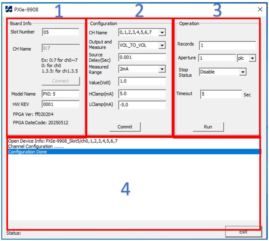
The PXIe-9908 driver installation package includes a ready-to-use graphical utility called the Software Front Panel (SFP).

The Software Front Panel allows users to configure the hardware according to user-defined operating conditions and immediately apply the configured settings.
![PXIe-9908\nBoard Info\nSlot Number 05\nCH Name 0:7\nEx: 0:7 for ch0~7\n0: for ch0\n1.3.5: for ch1.3.5\nConnect\nModel Name PXI: 5\nHW REV 0001\nFPGA Ver: ff020204\nFPGA DateCode: 20250512\nConfiguration\nCH Name 0,1,2,3,4,5,6,7\nOutput and Measure VOL_TO_VOL\nSource Delay(Sec) 0.001\nMeasured Range 2mA\nValue(Volt) 1.0\nHClamp(mA) 5.0\nLClamp(mA) -5.0\nCommit\nOperation\nRecords 1\nAperture 1 plc\nStop Status Disable\nTimeout 5 Sec\nRun\nOpen Device Info: PXIe-9908_Slot5/ch0,1,2,3,4,5,6,7\nChannel Configuration ......\nConfiguration Done\n4\nStatus:\nExit](.pxie-9908-50m-38010-1000-10/4b4435b76b24f813188ab8d98f589c35d5f31f7b76ae6dea0b0952cb1dc97938.jpg)

The Software Front Panel is divided into four functional areas:

1. Hardware Information Panel: Used to retrieve and display hardware-related information, including the firmware version installed on the board.
2. Channel Configuration Panel: Used to configure the operating mode and the voltage/current operating range for each channel.
3. Parameter Application Panel: Used to apply the configured channel parameters.
4. Message Panel: Operation messages appear in this area.

# Safety Instructions

For user safety, please read and follow all instructions, Warnings, Cautions, and Notes marked in this manual and on the associated device before handling/operating the device, to avoid injury or damage.

S'il vous plaît prêter attention stricte à tous les avertissements et mises en garde figurant sur l'appareil , pour éviter des blessures ou des dommages.

► Read these safety instructions carefully.
► Keep the User’s Manual for future reference.
► Read the Specifications section of this manual for detailed information on the recommended operating environment.
► When installing/mounting or uninstalling/removing device; or when removal of a chassis cover is required for user servicing:

[> Turn off power and unplug any power cords/cables.

[> Reinstall all chassis covers before restoring power.

► To avoid electrical shock and/or damage to device:

[> Keep device away from water or liquid sources.
[> Keep device away from high heat or humidity.
[> Keep device properly ventilated (do not block or cover ventilation openings).
[> Always use recommended voltage and power source settings.
[> Always install and operate device near an easily accessible electrical outlet.
[> Secure the power cord (do not place any object on/over the power cord) and connect it to a socket-outlet with earthing connection.
[> Only install/attach and operate device on stable surfaces and/or recommended mountings.

► If the device will not be used for long periods of time, turn off and unplug from its power source.
► Never attempt to repair the device, which should only be serviced by qualified technical personnel using suitable tools.
► A Lithium-type battery may be provided for uninterrupted backup or emergency power.

![The image shows a yellow triangle with a black border containing a large black exclamation point in the center.](.pxie-9908-50m-38010-1000-10/0d1095dc009c9883012b8e1fefee3d030446ac4777ebe9ada602e76f217877b5.jpg)
CAUTION:

Risk of explosion if battery is replaced with one of an incorrect type; please dispose of used batteries appropriately.

Risque d’explosion si la pile est remplacée par une autre de type incorrect. Veuillez jeter les piles usagées de façon appropriée.

► The device must be serviced by authorized technicians when:

[> The power cord or plug is damaged.
[> Liquid has entered the device interior.
[> The device has been exposed to high humidity and/or moisture.
[> The device is not functioning or does not function according to the User’s Manual.
[> The device has been dropped and/or damaged and/or shows obvious signs of breakage.

► Disconnect the power supply cord before loosening the thumbscrews and always fasten the thumbscrews with a screwdriver before starting the system up.

[> The equipment is not intended to be installed or used in a home, school, or public area accessible to the general population.
[> The knurled thumb screws with slotted heads for each Node module should be tightened with a tool after both initial installation and subsequent use.

► It is recommended that the device be installed only in a server room or computer room where access is:

[> Restricted to qualified service personnel or users familiar with restrictions applied to the location, reasons therefore, and any precautions required.
[> Only afforded by the use of a tool or lock and key, or other means of security, and controlled by the authority responsible for the location.

► Please use an approved power source certified by IEC or UL. If you need an adapter, optional accessories, or further assistance, please contact ADLINK for more information.

![This image shows a yellow triangular warning sign with a thick black border. Inside the triangle is a black symbol consisting of three vertical wavy lines rising above a horizontal line, which is the standard symbol for a hot surface hazard.](.pxie-9908-50m-38010-1000-10/82a80a118abb1c29f34effa9bf106c9ac4b0d111ed3fb5d95ace36f74f115e0b.jpg)

# BURN HAZARD

Touching this surface could result in bodily injury. To reduce risk, allow the surface to cool before touching.

# RISQUE DE BRÛLURES

Ne touchez pas cette surface, cela pourrait entraîner des blessures. Pour éviter tout danger, laissez la surface refroidir avant de la toucher.

► Lisez attentivement ces consignes de sécurité
► Conservez le manuel de l'utilisateur pour pouvoir le consulter ultérieurement
Lisez la section Spécifications de ce manuel pour des informations détaillées sur l'environnement d'exploitation recommandé
Lors de l'installation/montage ou de la désinstallation/retrait de l'appareil ; ou lorsque le retrait d'un boîtier est nécessaire pour l'entretien par l'utilisateur (voir Mise en route) :
► Éteignez l'alimentation et débranchez tous les cordons/câbles d'alimentation.
► Réinstallez tous les panneaux du boîtier avant de remettre l'alimentation sous tension.
► Pour éviter les chocs électriques et/ou d’endommager l’appareil :

► Tenez l'appareil à l'écart de toute source d'eau ou de liquide
► Tenez l'appareil à l'écart d'une forte chaleur ou d'une humidité élevée
► Maintenez l'appareil correctement ventilé (n'obstruer ou ne couvrez pas les ouvertures de ventilation)
► Utilisez toujours les réglages de tension et de source d'alimentation recommandés
► Installez et utilisez toujours l'appareil près d'une prise de courant facilement accessible
Fixez le cordon d'alimentation (ne placez aucun objet sur/au-dessus du cordon d'alimentation) et connectez-le à une prise de courant avec mise à la terre

► N'essayez jamais de réparer l'appareil, qui doit être réparé uniquement par du personnel technique qualifié et utilisant des outils appropriés.

► Lors de l'installation/montage ou de la désinstallation/retrait d'un périphérique, ou lorsque le retrait d'un couvercle de châssis est requis pour l'entretien par l'utilisateur :
► Coupez l’alimentation et débranchez tous les cordons/câbles d’alimentation.

► Réinstallez tous les capots du châssis avant de rétablir l'alimentation. Installez/fixez et utilisez l'appareil uniquement sur des surfaces stables et/ou des supports recommandés.

► Si l'appareil n'est pas utilisé pendant une longue période, éteignez-le et débranchez-le de sa source d'alimentation.

► Une batterie de type lithium peut être fournie pour une alimentation de secours ou de secours ininterrompue.

► L'appareil doit être réparé par des techniciens agréés lorsque :
► Le cordon d'alimentation ou la fiche est endommagé.
► Du liquide est entré dans l’appareil. € L'appareil a été exposé à une humidité élevée et/ou à l'humidité.
► L'appareil ne fonctionne pas ou ne fonctionne pas conformément au manuel de l'utilisateur.

► L'appareil est tombé et/ou a été endommagé et/ou présente des signes évidents de casse.
► Débranchez le cordon d'alimentation avant de desserrer les vis moletées et fixez toujours les vis moletées avec un tournevis avant de démarrer le système.
L'équipement n'est pas destiné à être installé ou utilisé dans une maison, une école ou une zone publique accessible au grand public.
Les vis à molette avec têtes fendue pour chaque module Node doivent être serrées avec un outil après l'installation initiale et lors de l'utilisation suivante.
► Il est recommandé d'installer l'appareil uniquement dans une salle de serveurs ou une salle informatique dont l'accès est :

Réservé au personnel de service qualifié ou aux utilisateurs familiers avec les restrictions appliquées à l'emplacement, les raisons de celles-ci et les précautions requises.
Autorisé uniquement par l'utilisation d'un outil ou d'une serrure et d'une clé, ou d'autres moyens de sécurité, et contrôlé par l'autorité responsable du lieu.

Veuillez utiliser une source d'alimentation approuvée et certifiée par la norme IEC ou UL. Si vous avez besoin d'un adaptateur, d'accessoires en option ou d'une assistance supplémentaire, veuillez contacter ADLINK pour plus d'informations.

# Getting Service

Ask an Expert: https://www.adlinktech.com/en/Askanexpert

# ADLINK Technology, Inc.

Address: No. 66, Huaya 1st Road, Guishan District Taoyuan City 333, Taiwan

Tel: +886-3-216-5088

Fax: +886-3-328-5723

Email: service@adlinktech.com

# Ampro ADLINK Technology, Inc.

Address: 6450 Via Del Oro, San Jose, CA 95119-1208, USA

Tel: +1-408-360-0200

Toll Free: +1-800-966-5200 (USA only)

Fax: +1-408-600-1189

Email: info@adlinktech.com

# ADLINK Technology (China) Co., Ltd.

Address: 300 Fang Chun Rd., Zhangjiang Hi-Tech Park, Pudong New Area Shanghai, 201203 China

Tel: +86-21-5132-8988

Fax: +86-21-5132-3588

Email: market@adlinktech.com

# ADLINK Technology GmbH

Address: Hans-Thoma-Strasse 8-10, 68163 Mannheim, Germany

Tel: +49-621-43214-0

Fax: +49-621 43214-30

Email: emea@adlinktech.com

Please visit the Contact page at www.adlinktech.com for information on how to contact the ADLINK regional office nearest you.
[🔗 Link to the original document](.pxie-9908-50m-38010-1000-10/pxie-9908-50m-38010-1000-10.pdf)