# PXIS-2508/PXIS-2558T

3U 8-Slot Smart and Portable PXI Chassis with Integrated LCD Touch Panel

User's Manual

Manual Rev. 2.01

Revision Date: August 24, 2007

Part No: 50-17026-2010

![The image displays a standard recycling symbol set against a black circular background. It features three white arrows arranged in a triangular loop, chasing each other. The arrows are stylized with parallel lines near their tails. There is no text in the image.](.pxis-2508-manual-8/0f9a942e999191ed6629a3e3bac6c6822da34f796b3efb88454d0486bf68c175.jpg)
Recycled Paper

Copyright 2007 ADLINK TECHNOLOGY INC.

All Rights Reserved.

# Disclaimer

The information in this document is subject to change without prior notice in order to improve reliability, design, and function and does not represent a commitment on the part of the manufacturer.

In no event will the manufacturer be liable for direct, indirect, special, incidental, or consequential damages arising out of the use or inability to use the product or documentation, even if advised of the possibility of such damages.

This document contains proprietary information protected by copyright. All rights are reserved. No part of this manual may be reproduced by any mechanical, electronic, or other means in any form without prior written permission of the manufacturer.

# Trademark Information

PXI is registered trademarks of PXI Systems Alliance. Other product names mentioned herein are used for identification purposes only and may be trademarks and/or registered trademarks of their respective companies.

# Getting service

Customer satisfaction is our top priority. Contact us should you require any service or assistance.

# ADLINK TECHNOLOGY INC.

Web Site http://www.adlinktech.com

Sales & Service service@adlinktech.com

Telephone No. +886-2-8226-5877

Fax No. +886-2-8226-5717

Mailing Address 9F No. 166 Jian Yi Road, Chungho City,

Taipei Hsien 235, Taiwan, ROC

# ADLINK TECHNOLOGY AMERICA, INC.

Sales & Service info@adlinktech.com

Toll-Free +1-866-4-ADLINK (235465)

Fax No. +1-949-727-2099

Mailing Address 8900 Research Drive, Irvine,

CA 92618, USA

# ADLINK TECHNOLOGY EUROPEAN SALES OFFICE

Sales & Service emea@adlinktech.com

Toll-Free +49-211-4955552

Fax No. +49-211-4955557

Mailing Address    Nord Carree 3, 40477 Düsseldorf, Germany

# ADLINK TECHNOLOGY SINGAPORE PTE LTD.

Sales & Service singapore@adlinktech.com

Telephone No. +65-6844-2261

Fax No. +65-6844-2263

Mailing Address 84 Genting Lane #07-02A,

Cityneon Design Center, Singapore 349584

# ADLINK TECHNOLOGY SINGAPORE PTE LTD.

# (INDIA Liaison Office)

Sales & Service india@adlinktech.com

Telephone No. +91-80-57605817

Fax No. +91-80-26671806

Mailing Address No. 1357, Ground Floor, "Anupama",

Aurobindo Marg JP Nagar (Ph-1)

Bangalore - 560078

# ADLINK TECHNOLOGY INC. (KOREA Liaison Office)

Sales & Service korea@adlinktech.com

Telephone No. +82-2-20570565

Fax No. +82-2-20570563

Mailing Address 4F, Kostech Building, 262-2,

Yangjae-Dong, Seocho-Gu,

Seoul, 137-130, South Korea

# ADLINK TECHNOLOGY (BEIJING) CO., LTD.

Sales & Service market@adlinkchina.com.cn

Telephone No. +86-10-5885-8666

Fax No. +86-10-5885-8625

Mailing Address Room 801, Building E, Yingchuangdongli

Plaza, No.1 Shangdidonglu,

Haidian District, Beijing, China

# ADLINK TECHNOLOGY (SHANGHAI) CO., LTD.

Sales & Service market@adlinkchina.com.cn

Telephone No. +86-21-6495-5210

Fax No. +86-21-5450-0414

Mailing Address Floor 4, Bldg. 39, Caoheting Science and

Technology Park, No.333 Qinjiang Road,

Shanghai, China

# ADLINK TECHNOLOGY (SHENZEN) CO., LTD.

Sales & Service market@adlinkchina.com.cn

Telephone No. +86-755-2643-4858

Fax No. +86-755-2664-6353

Mailing Address C Block, 2nd Floor, Building A1,

Cyber-tech Zone, Gaoxin Ave. 7.S,

High-tech Industrial Park S.,

Nanshan District, Shenzhen,

Guangdong Province, China

# Using this manual

# Audience and scope

This manual guides you when using the portable ADLINK PXI chassis. This manual is intended for system integrators, computer programmers, and hardware engineers with advanced knowledge of PXI/cPCI systems and PXI-based data acquisition.

# How this manual is organized

This manual is organized as follows:

Chapter 1 Introduction: This chapter introduces the PXIS-2508/2558T chassis including its features, specifications, and package contents.

Chapter 2 Chassis Overview: This chapter presents the chassis layout, location of basic components, dimensions, and backplane information.

Chapter 3 Installation: This part describes the procedures on how to install a system controller and peripheral modules into the PXIS-2508/2558T. It also contains information on OS and driver installations and touch panel usage.

Chapter 4 Remote Management: The chapter illustrates the remote management features of the PXIS-2508/2558T.

Appendix A: The Appendix comes with a troubleshooting section for common installation problems and tells you how to maintain the PXIS-2508/2558T chassis.

Important Safety Instructions: This section lists important safety reminders that you have to observe when using the chassis.

Warranty Policy: This presents the ADLINK Warranty Policy terms and coverages.

# Conventions

Take note of the following conventions used throughout the manual to make sure that you perform certain tasks and instructions properly.

NOTE Additional information, aids, and tips that help you perform particular tasks.

IMPORTANT Critical information and instructions that you MUST perform to complete a task.

WARNING Information that prevents physical injury, data loss, module damage, program corruption etc. when trying to complete a particular task.

# Table of Contents

# List of Figures .... iii

# 1 Introduction ...... 1

1.1 Features.... 2
1.2 Specifications.... 3
1.3 Unpacking Checklist 5

# 2 Chassis Overview.... 7

2.1 Views 7

Front Panel 7
Rear Panel 9
Left Panel 10
Right Panel 11
Top Panel 12
Base Panel 13

2.2 Backplane Features.... 14

Inter-operability with CompactPCI 14
System Controller Slot 14
Star Trigger Slot 14
Peripheral Slots 15
Local Bus 15
Trigger Bus 16
System Reference Clock 16

# 3 Installation 17

3.1 Installing the System Controller 17
3.2 Installing Peripheral Modules.... 19
3.3 Cooling Considerations.... 21
3.4 Powering up the System.... 22
3.5 Installing the OS 24
3.6 Installing Device Drivers 24

Installing the Chassis Description File (chassis.ini) ..... 24
Installing the VGA driver (PXIS-2558T only) 25
Installing the Touch Panel Driver (PXIS-2558T only) ... 26
Calibrating the Touch Panel 27
Using the Touch Panel (PXIS-2558T only) 29

# 4 Remote Management.... 31

4.1 Installing the Monitor Utility 32
4.2 Monitoring the System 33

Using the Monitor Utility (PXISRemoteMonUtil) ...... 33

Using the Monitoring/Control Function Library ..... 35

# A Troubleshooting and Maintenance.... 43

A.1 Installation Problems.... 43
A.2 BIOS Beeps 43
A.3 Basic Troubleshooting 44
A.4 Maintenance 46

Taking Care of the Touch Panel LCD
(PXIS-2558T only) 46

Changing the Fan Filter 46
Handling the Chassis 48
Handling Cables 48
Cleaning the Exterior 48
Power Requirements 48

# Important Safety Instructions.... 49

# Warranty Policy 51

# List of Figures

Figure 2-1: PXIS-2508/2558T Front Panel 7

Figure 2-2: PXIS-2508/2558T Rear Panel 9

Figure 2-3: PXIS-2508/2558T Left Panel....10

Figure 2-4: PXIS-2508/2558T Right Panel 11

Figure 2-5: PXIS-2508/2558T Top Panel.... 12

Figure 2-6: PXIS-2508/2558T Base Panel.... 13

Figure 2-7: PXI Bus Signal Routing 15

# 1 Introduction

The ADLINK PXIS-2508/2558T is a highly portable 3U PXI chassis equipped with advanced features and functionalities that comply with PXI and CompactPCI specifications. Offering one system slot and seven peripheral slots, the PXIS-2508/2558T is set in a sleek and lightweight chassis for superior portability, wider operating temperature range, lower operating noise, and robust system build.

Equipped with an intelligent control board and sensors, the PXIS-2508/2558T dynamically monitors and manages the chassis status including the fan speed, system voltages, and internal temperature. Remote management is supported as the control board exports these sensor readings directly to a remote computer using the standard RS-232 port.

The PXIS-2558T is a derivative model with an integrated 8.4" LCD that supports an 800x600 resolution and touch panel capability. The integrated display allows you to carry the PXI-based testing equipment anytime and anywhere. Combined with the high-performance ADLINK PXI-3800 Series (PXIS-2558T-A) or PXI-3900 Series (PXIS-2558T-B) controller, the PXIS-2558T delivers a complete testing equipment that is suitable for a variety of applications.

These PXI chassis come with an industrial-grade 350 W AC power supply, front panel LEDs, and easy-access PXI/CompactPCI slots with card guides for convenient installation and use. With innovative features and robust design, the PXIS-2508 and PXIS-2558T are your best choices of PXI platform for all your test and measurement requirements.

![Front view of a white electronic device with blue ports and indicator lights (no visible text or labels)](.pxis-2508-manual-8/bcd5cd211788b829e8dbeb6b8988a649c096a2e4f785279671046ae0ed1e3c25.jpg)

PXIS-2508

![Front view of a laboratory instrument with blue and white casing, no visible text or symbols on the device body](.pxis-2508-manual-8/a7f8ce8cb230bc7ab2135f44d6556ccf4dc06e0449f2f75b495c59203beb22c4.jpg)

PXIS-2558T

# 1.1 Features

▶ Compliant with PXI Specification Rev. 2.2
▶ Compact 8-slot PXI chassis with one system slot and seven PXI/CompactPCI peripheral slots
▶ 0°C to 55°C extended operating temperature range
▶ 41.6 dBA silent operation
▶ Intelligent chassis management

▶ Automatic fan speed control
▷ Round-the-clock chassis status monitoring
▶ Remote chassis management including on/off control

▶ 5.9 kg lightweight aluminum-metal construction
▶ 8.4" built-in LCD with touch panel (PXIS-2558T only)
▶ 350 W industrial-grade AC power supply
▶ Power, temperature, and fan monitoring LEDs

# 1.2 Specifications

<table><tr><td colspan="2">Power supply</td></tr><tr><td colspan="2">AC Input</td></tr><tr><td>Input voltage range</td><td>100 V to 240 V</td></tr><tr><td>Input voltage frequency</td><td>50 to 60 Hz</td></tr><tr><td>Input current rating</td><td>8 A/115 V or 4 A/230 V</td></tr><tr><td colspan="2">DC Output $^{1}$ </td></tr><tr><td>Total DC power output</td><td>350 W</td></tr><tr><td colspan="2">Integrated devices (PXIS-2558T only)</td></tr><tr><td>Display</td><td>8.4” TFT LCD with 800x600 resolution</td></tr><tr><td>Input devices</td><td>Built-in touch panel</td></tr><tr><td colspan="2">Cooling</td></tr><tr><td>Fans</td><td>2 x 60 CFM fans with filters</td></tr><tr><td>Per slot cooling capacity</td><td>25 W (verified by 55°C chamber test)</td></tr><tr><td colspan="2">Acoustic emissions</td></tr><tr><td colspan="2">Sound Pressure Level (dBA) measure at operator position $^{2}$ </td></tr><tr><td>Minimum fan speed</td><td>41.6 dBA</td></tr><tr><td>Maximum fan speed</td><td>47.3 dBA</td></tr><tr><td colspan="2">Sound Power (dBA) $^{3}$ </td></tr><tr><td>Minimum fan speed</td><td>51.9 dBA</td></tr><tr><td>Maximum fan speed</td><td>55.5 dBA</td></tr><tr><td colspan="2">Physical</td></tr><tr><td>PXI slots</td><td>8 (1 system slot and 7 peripheral slots)</td></tr><tr><td>Dimension</td><td>280 mm x 177 mm x 303 mm (W x H x D)</td></tr><tr><td colspan="2">Weight</td></tr><tr><td>PXIS-2508</td><td>5.9 kg (13 lbs)</td></tr><tr><td>PXIS-2558T</td><td>6.4 kg (14 lbs)</td></tr><tr><td colspan="2">Operating environment</td></tr><tr><td>Ambient temperature</td><td>0°C to 55°C</td></tr><tr><td>Relative humidity</td><td>10% to 90%, non-condensing</td></tr></table>

Storage environment
Ambient temperature

<table><tr><td>PXIS-2508</td><td>-20°C to 70°C</td></tr><tr><td>PXIS-2558T</td><td>0°C to 70°C</td></tr><tr><td>Relative humidity</td><td>10% to 90%, non-condensing</td></tr></table>

Shock and vibration

<table><tr><td>Functional shock</td><td>30 G half-sine, 11 ms pulse duration</td></tr></table>

Random vibration

<table><tr><td>Operating</td><td>5 Hz to 500 Hz, 0.5 Grms, 3 axes</td></tr><tr><td>Non-operating</td><td>5 Hz to 500 Hz, 2.46 Grms, 3 axes</td></tr></table>

Certifications

<table><tr><td>Safety</td><td>IEC 61010-1/EN 61010-1</td></tr></table>

Electromagnetic compatibility

<table><tr><td>Emissions</td><td>EN 55011 Class A</td></tr><tr><td>Immunity</td><td>EN 61326-1</td></tr><tr><td>CE compliance</td><td>The PXIS-2508 and PXIS-2558T meet the essential requirements of applicable European Directives</td></tr></table>

$^{1}$ See DC Output Table below.
2 Measured at operator position, tested in accordance with ISO 7779:1999/Amd.1:2003(E)
3 Tested in accordance with ISO 7779:1999/Amd.1:2003(E)

\*Specifications are subject to change without notice.

DC Output Table

<table><tr><td>VDC</td><td>Minimum</td><td>Maximum</td><td>Load Regulation</td><td>Max. Ripple &amp; Noise</td></tr><tr><td>+5 V</td><td>3.0 A</td><td>35 A</td><td>±5%</td><td>50 mV</td></tr><tr><td>+12 V</td><td>2.0 A</td><td>18 A</td><td>±5%</td><td>120 mV</td></tr><tr><td>+3.3 V</td><td>1.0 A</td><td>20 A</td><td>±5%</td><td>50 mV</td></tr><tr><td>-12 V</td><td>0.1 A</td><td>2 A</td><td>±10%</td><td>150 mV</td></tr></table>

The combined output power of +5V and +3.3V shall not exceed 35A.

# 1.3 Unpacking Checklist

Before unpacking, check the shipping carton for any damage. If the shipping carton and/or contents are damaged, inform your dealer immediately. Retain the shipping carton and packing materials for inspection. Obtain authorization from your dealer before returning any product to ADLINK.

Check if the following items are included in the package.

<table><tr><td>Item</td><td>PXIS-2508</td><td>PXIS-2558T-A</td><td>PXIS-2558T-B</td></tr><tr><td>3U 8-slot PXI chassis with 350 W AC power supply and</td><td>O</td><td>X</td><td>X</td></tr><tr><td>3U 8-slot PXI chassis with 8.4&quot; touch panel LCD and 350 W AC power supply</td><td>X</td><td>O</td><td>O</td></tr><tr><td>Power cords (110 V and 220 V)</td><td>O</td><td>O</td><td>O</td></tr><tr><td>Filler panel kit for unused/reserved slots including one 3-slot panel and seven 1-slot panels</td><td>O</td><td>O</td><td>O</td></tr><tr><td>Touch panel stylus with two holders</td><td>X</td><td>O</td><td>O</td></tr><tr><td>Two extra fan filters</td><td>O</td><td>O</td><td>O</td></tr><tr><td>ADLINK All-in-One CD</td><td>O</td><td>O</td><td>O</td></tr><tr><td>User&#x27;s manual</td><td>O</td><td>O</td><td>O</td></tr></table>

# NOTE

OEM version package may vary depending on customer requests. The assigned controller and/or peripheral modules may be pre-installed and shipped with the chassis. Inquire with your dealer for additional information on these options.

# 2 Chassis Overview

This section describes the PXIS-2508/2558T chassis including the location of basic components and control, dimensions, and backplane features.

# 2.1 Views

Front Panel
![LCD\nPower LED\nFan LED\nTemp LED\nAlarm reset button\nStandby power switch\nUSB ports\nFoot stand\nPXIS-2558T\nPower LED\nFan LED\nTemp LED\nAlarm reset button\nStandby power switch\nSystem slot Peripheral slots\nPXIS-2508](.pxis-2508-manual-8/a5e2699f77f0fe5d17ef9e8650435750582a698daa912005d6c8ff68f1c11992.jpg)

Figure 2-1: PXIS-2508/2558T Front Panel

LED Indications

<table><tr><td rowspan="2">LED</td><td colspan="3">Status</td></tr><tr><td>On</td><td>Off</td><td>Blinking</td></tr><tr><td>Power (Blue)</td><td>DC voltages are supplied normally.</td><td>No DC power is supplied.</td><td>5 V or 3.3 V exceeds ±7% range12 V or -12 V exceeds ±12% range</td></tr><tr><td>Fan (Green)</td><td>Fans are operating normally.</td><td>The system is off.</td><td>Any of the fans is operating in a speed lower than 500 RPM</td></tr><tr><td>Temp (Amber)</td><td>Chassis temperature is normal</td><td>The system is off.</td><td>Chassis temperature exceeds 50°C</td></tr></table>

# Alarm Reset Button

The alarm reset button enables you to stop the chassis alarm during an error or critical system event. To stop the alarm, press the alarm reset button.

Rear Panel
![The image displays two diagrams of blue-framed electronic devices.\n\nThe top device is labeled **PXIS-2558T**. On its left side, labels identify the 'Main power switch,' 'Power connector,' 'Power supply fan,' and 'Remote monitoring port.' On the right side, labels identify the 'System slot' and 'Peripheral slots.' At the bottom, a label indicates the 'Foot stand.'\n\nThe bottom device is labeled **PXIS-2508**. On its right side, labels identify the 'Power supply fan,' 'Power connector,' 'Main power switch,' and 'Remote monitoring port.' The left side of the device is blank.](.pxis-2508-manual-8/9dd41836b2a412755da588f67d64d8b1e09e573724f1f50d3e88072c59c57ae5.jpg)
Figure 2-2: PXIS-2508/2558T Rear Panel

# Left Panel

![This image displays a front view of a piece of equipment, labeled at the bottom with the text 'PXIS-2558T'. The device features a white front panel framed by a blue top and bottom section. Centered on the front is a large horizontal handle mechanism with a grey central grip. The text 'Handle' appears above this mechanism with a vertical line pointing to the grey grip. The unit stands on black feet, and a black power cord is visible on the bottom right. A small circular indicator or button is located near the bottom center of the white panel.](.pxis-2508-manual-8/9b6c33ac1c81ef82df439a445c4ec113c2a1a10a168b37c0064353567cf079a2.jpg)

![Power supply inlet apertures\nPXIS-2508](.pxis-2508-manual-8/31a0e8e4d3719517c54aff4b01fba91d87fbe284814bdaa4c8cc71db5a3e2dd6.jpg)

Figure 2-3: PXIS-2508/2558T Left Panel

Right Panel
![Power supply air inlet\nPXIS-2558T](.pxis-2508-manual-8/c133c8b72df7ad888efd195840e385edc54eb9e5b8845b17609c27fbeaf97af1.jpg)

![Handle\nPXIS-2508](.pxis-2508-manual-8/22f4e3f87bdaa42b540a1c4cde2eaa21f0f51f89f57c4a4736c6338a28ba04f4.jpg)

Figure 2-4: PXIS-2508/2558T Right Panel

# Top Panel

![Outlet apertures](.pxis-2508-manual-8/0e51dd6a7b1b134dcb39813b58779b06b77692cd06bf6ddee207715ca00e1815.jpg)

PXIS-2558T

![Outlet apertures](.pxis-2508-manual-8/c149f261e95dfea03f33dababa99bb92b9a6c517f4732ac0b295515d04e73c36.jpg)

PXIS-2508
Figure 2-5: PXIS-2508/2558T Top Panel

# Base Panel

![Inlet apertures](.pxis-2508-manual-8/b1b8bac28be0a43d4df4f674d57a5c7ea6c1bdb9c5da56a1fd9ef803f01b3728.jpg)

PXIS-2558T

![Inlet apertures](.pxis-2508-manual-8/51e9052801112b8e368110ea234a058f3963bff44d1e36848c7cdc8db99af00a.jpg)

PXIS-2508
Figure 2-6: PXIS-2508/2558T Base Panel

# 2.2 Backplane Features

# Inter-operability with CompactPCI

With backplanes that are compliant with PXI Specification Rev. 2.2, the PXIS-2508 and PXIS-2558T are designed to support both standard PXI and CompactPCI modules.

The signals on the backplane's P1 connector meet the requirements of CompactPCI specifications for both peripheral and system modules. The PXI-specific signals located on P2 are reserved or unused in CompactPCI 64-bit specifications. This allows peripheral modules with CompactPCI 64-bit specifications to function in both PXIS-2508 and PXIS-2558T.

# NOTE

CompactPCI peripheral modules which operate with rear I/O modules may not work in PXIS-2508/2558T due to the conflict between rear I/O signals and PXI-specific signals on J2.

# System Controller Slot

Slot 1 is designated as the system controller slot as defined by PXI specifications. The PXIS-2508/PXIS-2558T can accommodate a PXI system controller with up to 3-slot width. As defined in PXI specifications, the system controller slot allows the controller to expand to the left to prevent it from occupying the peripheral slot space.

# Star Trigger Slot

Slot 2 is designated as the star trigger (ST) slot. This slot comes with dedicated trigger lines between itself and peripheral slots 3 to 8. The star trigger functionality is intended to provide precise trigger signals to the peripheral modules by installing a specific star trigger controller modules in the ST slot. The star trigger slot can be also used as a general peripheral slot if you will not use the star trigger functionality.

# Peripheral Slots

The PXIS-2508/2558T comes with seven peripheral slots including the star trigger slot. Each peripheral slot supports a 3U PXI/CompactPCI peripheral module.

![Based on the provided block diagram, here are the labeled blocks and their connections:\n\n**Labeled Blocks:**\n*   Clock 10 MHz Buffer Circuitry\n*   System Controller\n*   Star Trigger Controller\n*   Peripheral slot (appears six times)\n*   Local Bus (appears six times)\n*   PXI Trigger Bus Segment and PCI Bus Segment\n\n**Connections:**\n*   **Clock 10 MHz Buffer Circuitry** connects to **System Controller**, **Star Trigger Controller**, and all six **Peripheral slot** blocks via downward lines labeled **PXI Star Triggers**.\n*   **PXI Trigger Bus Segment and PCI Bus Segment** connects to **System Controller**, **Star Trigger Controller**, and all six **Peripheral slot** blocks via bidirectional arrows.\n*   **Local Bus** blocks connect **Star Trigger Controller** to the first **Peripheral slot**, and sequentially connect each **Peripheral slot** to the next adjacent **Peripheral slot**.](.pxis-2508-manual-8/8b45475c34fb50a3c9e4de7ca20789ce98aa6b126153117d0914a178bc1fa602.jpg)

Figure 2-7: PXI Bus Signal Routing

# Local Bus

The PXI backplane local bus is a daisy-chained bus that connects each peripheral slot with its adjacent (left/right) peripheral slots. Each local bus has 13 lines and can transmit analog or digital signals between modules. It also provides a high-speed side-band communication path that does not affect the PXI bandwidth.

Based on PXI specifications, the local bus connects all adjacent slots except slots 1 and 2.

# Trigger Bus

The trigger bus is an 8-line bus that connects all PXI slots in the same PCI segment. You can use the trigger bus as an intermodule synchronization mechanism. PXI modules can transmit trigger or clock signals to one another through the trigger bus, enabling precise timed responses to asynchronous external events that the system is monitoring or controlling.

# System Reference Clock

The backplane comes with a PXI 10 MHz system reference clock (PXI\_CLK10). An independent buffer (having source impedance matched to the backplane and a skew of less than 1 ns between slots) drives the clock signal generated from a high-precision oscillator to each peripheral slot. You can use this common reference clock signal to synchronize multiple modules in a PXI chassis.

# 3 Installation

The chapter tells you how to install the system controller, peripheral modules, and drivers to the PXIS-2508/2558T chassis. It also provides information on cooling considerations, and installation/calibration of the touch panel (PXIS-2558T only)

# 3.1 Installing the System Controller

The PXIS-2508/2558T comes with a system controller slot that supports a PXI system controller. We recommend the following system controllers for use with the PXIS-2558T:

▶ PXI-3800 Series for PXIS-2558T-A model
▶ PXI-3900 Series for PXIS-2558T-B model

To install the system controller:

1. Make sure that the CPU, memory module(s), and storage device(s) are properly installed on the system controller module.
2. Locate the system controller slot (Slot 1).

![Front view of a blue and white industrial machine with internal components and red arrows pointing to ports (no visible text or symbols)](.pxis-2508-manual-8/7a1220b0854b60a38e4ad6f09da4feb494e43cab1c47b9807c61173f16601fe6.jpg)

3. Push down (loose) the system controller module's ejector/injector handle(s).

4. Align the module's top and bottom edges to the card guides, then carefully slide the module into the chassis,

![Hand inserting a component into an open industrial control unit (no visible text or labels)](.pxis-2508-manual-8/518ce78346a8f048b388f7b99864ab25cd6b470b32c21b99ece397e3131c61c1.jpg)

5. Pull up the ejector/injector handle(s) until the module is properly connected to the chassis backplane.

![Front view of an electronic testing device with internal components and a red arrow pointing to a component (no visible text or symbols)](.pxis-2508-manual-8/59f937296be0c8dce203ecd0aca6e3b31ad09927a7d2e22ff7d73132b2bb0ea8.jpg)

6. Fasten the screws on the module front panel, then connect all devices to the system controller.

![Interior view of an electronic device showing a rack-mounted module with ports and a hand inserting a cable (no visible text or labels)](.pxis-2508-manual-8/3c4391a5cbe7c8cc0df183873e5ca1a677236a8e2b6f641784b78dc1ea96d4b7.jpg)

# 3.2 Installing Peripheral Modules

The PXIS-2508/2558T supports up to seven PXI/cPCI peripheral modules, including a star trigger module.

To install a peripheral module:

1. Select an available peripheral slot (slots 2 to 8).
2. Push down (loose) the peripheral module's ejector/injector handle(s), then align the module's top and bottom edges to the card guides.
3. Carefully slide the module into the chassis..

![Interior view of an open industrial testing machine with visible circuit boards and a red arrow pointing to the internal components (no text or symbols present)](.pxis-2508-manual-8/0ff6b692c79b1860371d0b62dac1ad5ba291c870ec13cb8c920cab5453a532e0.jpg)

4. Pull up the ejector/injector handle until the module is properly connected to the chassis backplane.

![Hand inserting a cable into an open industrial control panel (no visible text or labels)](.pxis-2508-manual-8/1fd159a91800e31156cb513330a30909c64bfb5b3974669026c7aef4a14c6696.jpg)

5. Fasten the screw on the module front panel, then connect all devices.

![Front view of an electronic testing device with internal components and a blue outline (no visible text or labels)](.pxis-2508-manual-8/819798bcb907f37e0c68937afdc0ed98c5d95ce40ee6388fda43571ab33984e3.jpg)

# 3.3 Cooling Considerations

The PXIS-2508/2558T implements a forced air-cooling mechanism to maintain a stable chassis and power supply temperature. Room/cold air is taken in by internal chassis fans from the air inlet apertures at the bottom of the chassis while hot air is exhausted though the air outlet apertures on top. Refer to the illustration below.

![Front view of a white electronic device with blue casing and red/blue directional arrows indicating flow or movement (no text or symbols on the device body)](.pxis-2508-manual-8/0ce03df997abb45ef6a613603d5a1c43ea2cf4d3559476cf64cd876c6f656cb0.jpg)

For bench top installations, provide adequate clearance for the air inlet and outlet apertures. Keep other objects or equipment at least 5 cm (2 in) away from the outlet apertures and avoid covering these holes. For optimum airflow, provide ample clearance for the air inlet apertures and open the foot stands, if possible.

There are also air inlet apertures on one side of the chassis for power supply ventilation. Hot air from the power supply is exhausted through the chassis rear. Maintain a 2.5 cm (1 in) clearance on the chassis sides for adequate power supply ventilation.

![Exterior view of a white and blue electronic device labeled 'ADLINK' with directional arrows indicating motion (no text or symbols on the device itself)](.pxis-2508-manual-8/78e7cb47b2e0e61f5ff3be73acd864e08e38facfeaa4786f25e31e20c8290012.jpg)

# 3.4 Powering up the System

The PXIS-2508/2558T is equipped with a universal power supply unit that does not require input voltage selection.

To turn on the system:

1. Connect one end of the supplied power cable to the power connector located at the rear side of the chassis.

![Power connector\nPXIS-2508\nPXIS-2558T](.pxis-2508-manual-8/00f92ee1859390022a8827746efb70e84925c27e3e578eb34e30eaa362dd8766.jpg)

2. Plug the other end of the AC power cord to a properly grounded wall socket or power strip.
3. Turn on the main power switch (|).

![Main power\nswitch\nPXIS-2508\nPXIS-2558T](.pxis-2508-manual-8/34d54ecf3785a01953be9d2ec2d1570bc2f9616218e4b4931dd4371169b5d749.jpg)

4. Turn on the standby power switch at the front panel. The power LED in the front panel lights up green and the chassis fans start to operate.

![Standby power\nswitch\nPXIS-2558T\nPXIS-2508](.pxis-2508-manual-8/670c195d70e838186d9124cf1d3f2e9cb87001b90c92881c4ba3e9ccfe4157fa.jpg)

To turn off the system:

1. Shut down the system via the operating system.
2. Move the standby power switch to standby position (⏻)

# OR

3. Turn off the main power switch (O).

# IMPORTANT

When you put the system into standby mode using the standby power switch, wait three seconds before you turn on the system again. This protects installed PXI modules from damage.

If you turn on the system immediately from standby-by mode, it may take at least three seconds for the POST messages to appear on screen.

# 3.5 Installing the OS

Install the operating system that your system controller supports. For more information, refer to the documentation provided by the operating system vendor and the system controller manual.

Most operating systems requires installation from a floppy or optical disk drive. These devices must be configured, installed, and tested with the supplied drivers before attempting to install a new operating system.

Consult the release notes and installation documentation provided by the operating system vendor for documentation discrepancies and/or compatibility issues, problems, and solutions.

# 3.6 Installing Device Drivers

# Installing the Chassis Description File (chassis.ini)

To allow inter-operability of PXI platform and modules from different vendors, PXI specifications define the hardware description files to describe the hardware characteristics in ASCII text format. System integrators can use the hardware description files to configure the system with various PXI controller, PXI chassis, and PXI modules.

ADLINK provides a complete list of the chassis description files (chassis.ini) for the PXI chassis. You can find the chassis description files in X:\Driver Installation\PXI Platform\PXI Platform Description\ (X: is the CD-ROM drive where you placed the ADLINK All-in-One CD). A simple how to document is also existed in the directory to illustrate the procedures of using the chassis description file with third-party software to build up your PXI system.

# Installing the VGA driver (PXIS-2558T only)

The PXIS-2558T is equipped with a 8.4" LCD with touch panel feature. You must install the correct drivers for the LCD and the touch panel to function.

There are two PXIS-2558T chassis derivatives: PXIS-2558T-A for use with an ADLINK PXI-3800 Series controller and PXIS-2558T-B for use with an ADLINK PXI-3900 Series controller. Make sure to install the correct drivers according to the installed controllers. You may find the VGA drivers in the ADLINK All-in-One CD. Refer to the list below:

For PXIS-2558T-A with a PXI-3800 controller, the VGA driver is located in this folder:

```batch
X:\Driver Installation\PXI Platform\PXI controller\PXI-3800\VGA\
```

For PXIS-2558T-B with a PXI-3910 or PXI-3920 controller, the VGA driver is located in this folder:

```batch
X:\Driver Installation\PXI Platform\PXI controller\PXI-3910_20\VGA\
```

For PXIS-2558T-B with a PXI-3950 controller, the VGA driver is located in this folder:

```batch
X:\Driver Installation\PXI Platform\PXI controller\PXI-3950\VGA\
```

To install the VGA driver:

1. Connect an external monitor to the VGA port of the PXI controller.

2. Adjust the PXI controller BIOS Setup to output the video signals using the rear panel I/O. Refer to the PXI controller documentation for details.

3. Install the correct VGA driver according to the PXI controller. Refer to the list above.

4. If the VGA driver supports dual-display mode, make sure the video signal is output to both display devices (monitor and notebook). Refer to the PXI controller documentation for details.

# Installing the Touch Panel Driver (PXIS-2558T only)

The PXIS-2558T LCD is equipped with touch panel functionality for convenient data input and GUI navigation.

To install the touch panel driver:

1. Connect a USB CD-/DVD-ROM to the system or PXI controller.
2. Place the ADLINK All-in-Once CD in the optical drive.
3. Locate the touch panel drivers in:

X:\Driver Installation\PXI Platform\PXI chassis\PXIS-2508\_2558T\Touch Panel\

then double-click on the Setup.exe file to begin installation.

4. After installation is finished, a calibration program appears. Refer to the next section for details.

# Calibrating the Touch Panel

After installing the touch panel driver, you need to calibrate the screen for accurate touch operation. The calibration tool (XTouchware) is automatically installed together with the touch panel driver.

To calibrate the touch panel:

1. Tap or double-click on the XTouchWare icon from the desktop or launch the utility from the Windows Start menu.
2. Tap or click on the Calibration button. A 4-point calibration window appears.

![XTouchWare\nGeneral | Monitors | About |\nController List\nActive Controller 	(??USB#Vid_DeefPid_0001#61407da6b\nInterface	Type	Version\n(??USB#Vid_Deef&Pid...	RESISTIVE	2.12\nAdd\nRemove\nLanguage\nEnglish\nCalibration	Draw Test\nAdvanced\nOK	Cancel	Help](.pxis-2508-manual-8/cf853cc5d6adf9c31ccd26f79bf6e79b3d8e7466fba525cd8a15b4d8e982803e.jpg)

3. Tap or click on the intersection of the blinking X symbol, then hold for a few seconds until it stops blinking. Repeat the process for all X symbols that will appear on four corners of the screen.

![Please touch the blinking symbol until stop blinking.](.pxis-2508-manual-8/0bcc95f5ca8c41447539c8d1520400356322d72c8f96d622b4bc990015cc3bd0.jpg)

4. When finished, click OK to store the calibration data.

![X TouchWare\nGeneral | Monitors | About |\nController List\nActive Controller	???USB#Vid_OeefPid_0001#61407da5b\nInterface	Type	Version\n???USB#Vid_Oeef&Pid...	RESISTIVE	2.12\nAdd\nValuation\n4 points calibration finished. Press Ok to continue.\nOK\nCalibration	Draw Test\nAdvanced\nOK	Cancel	Help](.pxis-2508-manual-8/6e7f4150618e8a667480025af69bd41ac2d8c2fd4cd102ee0acb2a430fce6287.jpg)

# Using the Touch Panel (PXIS-2558T only)

The PXIS-2558T touch panel LCD provides an intuitive way to interact with the operating system. You can use the touch panel as a replacement for a mouse. Use the supplied touch panel stylus or your finger to move the cursor onscreen. The table below lists all mouse operations and their corresponding touch panel equivalents.

<table><tr><td>Mouse operation</td><td>Touch panel</td></tr><tr><td>Left-click</td><td>Tap the screen once</td></tr><tr><td>Right-click</td><td>Tap and hold the screen for 3 to 5 seconds</td></tr><tr><td>Double-click</td><td>Tap the screen twice</td></tr><tr><td>Drag and drop</td><td>Tap the screen, then drag the window by moving the stylus or your finger</td></tr></table>

# 4 Remote Management

The PXIS-2508 and PXIS-2558T chassis provide an advanced remote monitoring and control functions. The chassis status, including it internal temperature, fan speed, and DC voltages, are exported via the standard RS-232 port located in the rear panel allowing you to monitor the system on a remote computer. You may also use a remote computer to turn the system on or off through the monitoring port by sending software commands.

![Remote\nmonitoring port\nPXIS-2508\nPXIS-2558T](.pxis-2508-manual-8/8aaf5384973a0610d65d989e541ce4d2a5e4d332a6a2f91a7f4dae28631bd1f5.jpg)

To remotely monitor and control the PXIS-2508/2558T, you need to connect the remote monitoring port to a remote computer using a standard RS-232 cable.

# 4.1 Installing the Monitor Utility

You can find a setup file to install the remote monitoring utility and function library in ADLINK All-in-One CD.

To install the monitoring utility:

1. Connect a USB CD-/DVD-ROM to the system controller.
2. Place the ADLINK All-in-Once CD in the optical drive.
3. Locate the monitoring utility in this folder:

```batch
X:\Driver Installation\PXI Platform\PXI chassis\PXIS-2508_2558T\RemoteMon\
```

then double-click on the Setup.exe file to begin installation.

# 4.2 Monitoring the System

# Using the Monitor Utility (PXISRemoteMonUtil)

To monitor the system using the monitor utility:

1. Launch the PXISRemoteMonUtil.
2. Select the COM port that connects the remote computer with the PXIS-2508/2558T (COM5 in this example).

![PXIS-2508/2558 Remote Mon. Utility\nCOM Port\nCOM1\nCOM1\nCOM2\nCOM3\nCOM4\nCOM5\nCOM6\nCOM7\nCOM8\nChassis Temperature (degree)\nT1: 0\nT2: 0\nFan Speed (RPM)\nF1: 0\nF2: 0\nInitialize RUN STOP\nDC Voltage (V)\n12V: 0\n5V: 0\n3.3V: 0\n-12V: 0](.pxis-2508-manual-8/c488ddbbd443d0637c6e40846695e411d28125235b1f8667bcb0d699f8f79ab0.jpg)

3. Click Initialize to initialize the COM port. If the COM port is successfully initialized, the RUN button is enabled.

![PXIS-2508/2558 Remote Mon. Utility\nCOM Port\nCOM5\nInitialize\nRUN\nSTOP\nChassis Status\nPower On/Off\nChassis Temperature (degree)\nT1: 0\nT2: 0\nFan Speed (RPM)\nF1: 0\nF2: 0\nDC Voltage (V)\n12V: 0\n5V: 0\n3.3V: 0\n-12V: 0](.pxis-2508-manual-8/6f6ec709b323d152fa9c758789889f5c5f8d23422baddc93b3be0087d88423d6.jpg)

4. Click the RUN to display the chassis temperature, fans' speed, and DC voltages. These values automatically update.

![PXIS-2508/2558 Remote Mon. Utility\nCOM Port\nCOM5\nInitialize\nRUN\nSTOP\nChassis Status\nPower On/Off\nON\nChassis Temperature (degree)\nT1: 28 Normal\nT2: 26 Normal\nFan Speed (RPM)\nF1: 1800 Normal\nF2: 1900 Normal\nDC Voltage (V)\n12V: 12.3 Normal\n5V: 5 Normal\n3.3V: 3.3 Normal\n-12V: -11.8 Normal](.pxis-2508-manual-8/d2d87453c10a1780c33b4fe2c00edc243abd6d0188961635e26c92d50c80dc90.jpg)

5. Click STOP to stop monitoring.

# Using the Monitoring/Control Function Library

You can use the monitoring/control function library to create a customized program that would monitor and control the PXIS-2508/2558T. Refer to the data structure and function library below.

# Data Structure

In the library, a data structure is defined to describe the chassis status.

```txt
typedef struct tagChassisStatus
{
    BYTE    PowerStatus

    //Fan status and RPM
    BYTE    Fan1Status;
    BYTE    Fan2Status;
    BYTE    Fan3Status;
    BYTE    Fan4Status;
    BYTE    Fan5Status;
    BYTE    Fan6Status;
    float    Fan1RPM;
    float    Fan2RPM;
    float    Fan3RPM;
    float    Fan4RPM;
    float    Fan5RPM;
    float    Fan6RPM;

    //Temperature sensor status and reading in degree centigrade
    BYTE    Temp1Status;
    BYTE    Temp2Status;
    float    Temp1Reading;
    float    Temp2Reading;

    //DC status and reading
    BYTE    DC1Status;
    BYTE    DC2Status;
    BYTE    DC3Status;
    BYTE    DC4Status;
    float    DC1Reading;
    float    DC2Reading;
    float    DC3Reading;
    float    DC4Reading;
```

BYTE Reserve1;

BYTE Reserve2;

} ChassisStatus;

The variables in the data structure are illustrated below.

<table><tr><td>Variable</td><td>Description</td><td>Type</td><td>Value</td></tr><tr><td>PowerStatus</td><td>Power On/Off status</td><td>BYTE</td><td>0: Off1: On</td></tr><tr><td>Fan1Status</td><td>Fan#1 operating status</td><td>BYTE</td><td>0: Normal1: Abnormal</td></tr><tr><td>Fan2Status</td><td>Fan#2 operating status</td><td>BYTE</td><td>0: Normal1: Abnormal</td></tr><tr><td>Fan3Status</td><td>Not used for PXIS-2508/2558T</td><td>BYTE</td><td>N/A</td></tr><tr><td>Fan4Status</td><td>Not used for PXIS-2508/2558T</td><td>BYTE</td><td>N/A</td></tr><tr><td>Fan5Status</td><td>Not used for PXIS-2508/2558T</td><td>BYTE</td><td>N/A</td></tr><tr><td>Fan6Status</td><td>Not used for PXIS-2508/2558T</td><td>BYTE</td><td>N/A</td></tr><tr><td>Fan1RPM</td><td>Fan#1 speed in RPM</td><td>float</td><td>RPM value</td></tr><tr><td>Fan2RPM</td><td>Fan#2 speed in RPM</td><td>float</td><td>RPM value</td></tr><tr><td>Fan3RPM</td><td>Not used for PXIS-2508/2558T</td><td>float</td><td>N/A</td></tr><tr><td>Fan4RPM</td><td>Not used for PXIS-2508/2558T</td><td>float</td><td>N/A</td></tr><tr><td>Fan5RPM</td><td>Not used for PXIS-2508/2558T</td><td>float</td><td>N/A</td></tr><tr><td>Fan5RPM</td><td>Not used for PXIS-2508/2558T</td><td>float</td><td>N/A</td></tr><tr><td>Temp1Status</td><td>Temperature sensor#1 status</td><td>BYTE</td><td>0: Normal1: Abnormal</td></tr><tr><td>Temp2Status</td><td>Temperature sensor#1 status</td><td>BYTE</td><td>0: Normal1: Abnormal</td></tr><tr><td>Temp1Reading</td><td>Reading of temperature sensor#1 in °C</td><td>float</td><td>Temperature value</td></tr><tr><td>Temp1Reading</td><td>Reading of temperature sensor#2 in °C</td><td>float</td><td>Temperature value</td></tr><tr><td>DC1Status</td><td>DC 12V status</td><td>BYTE</td><td>0: Normal1: Abnormal</td></tr><tr><td>DC2Status</td><td>DC 5V status</td><td>BYTE</td><td>0: Normal1: Abnormal</td></tr><tr><td>DC3Status</td><td>DC 3.3V status</td><td>BYTE</td><td>0: Normal1: Abnormal</td></tr><tr><td>DC4Status</td><td>DC -12V status</td><td>BYTE</td><td>0: Normal1: Abnormal</td></tr><tr><td>DC1Reading</td><td>DC 12V voltage reading</td><td>float</td><td>Voltage value</td></tr><tr><td>DC2Reading</td><td>DC 5V voltage reading</td><td>float</td><td>Voltage value</td></tr><tr><td>DC3Reading</td><td>DC 3.3V voltage reading</td><td>float</td><td>Voltage value</td></tr><tr><td>DC4Reading</td><td>DC -12V voltage reading</td><td>float</td><td>Voltage value</td></tr></table>

# Function Reference

# InitCOM

# Description

Initializes the remote computer COM port connected to the remote monitoring port of the PXIS-2508/2558T.

# Syntax

HANDLE InitCOM(LPCSTR com)

# Parameter

com A string denotes the COM port. Can be COM1 \~ COM8.

# Return Value

A handle to the initialized COM port. If the function returns NULL, the initialization of COM port failed.

# Example

HANDLE hCOM;
hCOM= InitCOM("COM1");

# GetChassisStatus

# Description

Gets the chassis status and stores the status in a ChassisStatus structure. You can invoke this function periodically to update the chassis status.

# Syntax

BOOL GetChassisStatus(HANDLE hCom, ChassisStatus\* Status)

# Parameters

hCom The initialized COM port.

Status ChassisStatus data structure that stores the chassis status

# Return Value

TRUE if the function succeeded. FALSE if the function failed.

# Example

```txt
ChassisStatus status;
BOOL ret;
ret = GetChassisStatus(hCom, &status);
```

# SetChassisPowerOn

# Description

Powers on the PXIS-2508/2558T.

# Syntax

BOOL SetChassisPowerOn (HANDLE hCom)

# Parameter

com The initialized COM port.

# Return Value

TRUE if the function succeeded. FALSE if the function failed.

# Example

BOOL ret;
ret= SetChassisPowerOn (hCom);

# SetChassisPowerOff

# Description

Powers off the PXIS-2508/2558T. You should shut down the system controller via the operating system before turning off the chassis power.

# Syntax

BOOL SetChassisPowerOff (HANDLE hCom)

# Parameter

com The initialized COM port.

# Return Value

TRUE if the function succeeded. FALSE if the function failed.

# Example

```javascript
BOOL ret;
ret= SetChassisPowerOff (hCom);
```

# CloseCOM

# Description

Closes the initialized COM port.

# Syntax

BOOL CloseCOM(HANDLE hCom)

# Parameter

com The initialized COM port.

# Return Value

TRUE if the function succeeded. FALSE if the function failed.

# Example

```txt
BOOL ret;
ret = CloseCOM (hCom);
```

# Appendix A Troubleshooting and Maintenance

# A.1 Installation Problems

Failure to start the system usually results from incorrect installation of the system controller, peripheral modules, and other components. Go through the following checklist before you start up the system.

▶ The system controller is properly installed and secured.
▶ All peripheral modules are properly seated on the slots.
▶ All cables are properly connected to the system controller/peripheral modules.
▶ All peripheral modules installed are compatible for use in the chassis.
▶ The power cord is properly plugged into the chassis power connector and power outlet/wall socket/power strip.

If the system fails to turn on even after all installation conditions are met, remove all peripheral modules that you installed, then try again. If the system turns on properly, try installing one peripheral module at a time, then test if the system will power-up. You may also try installing the modules into different slots until you get the desired result.

# A.2 BIOS Beeps

BIOS beeps indicate errors in system initialization. These beeps are usually associated with video and memory errors. If the system beeps during start up, check if the display is properly connected to the system controller or if the integrated LCD drivers (PXIS-2558T only) are properly installed. You may also check if the memory modules are properly installed in the system controller.

# A.3 Basic Troubleshooting

<table><tr><td>Problem</td><td>What to Do</td></tr><tr><td>System fails to power up</td><td>▶ Check if the power cord is properly plugged into the chassis power connector and wall socket/power strip. ▶ Check if the wall socket/power strip is live. ▶ Check if the main power switch at the back of the chassis is turned on. ▶ Make sure the standby power button at the chassis front panel is turned on.</td></tr><tr><td>There is no LCD display (PXIS-2558T only)</td><td>▶ Make sure the system is turned on. ▶ Connect an external display to the system controller's VGA port, then check if there is video output. ▶ If video output is present on the external display, adjust your display settings and enable LCD video. ▶ If video output is not present on the external display, check if the system controller is properly installed. ▶ If there is no video output even when the system controller is properly installed, contact ADLINK for further assistance.</td></tr><tr><td>There is no video output in the external display</td><td>▶ Redirect the video output to the integrated LCD (PXIS-2558T only). ▶ Check if your external display is functioning. ▶ Check your display settings and make sure you enable external video.</td></tr><tr><td>The touch panel doesn’t work</td><td>▸ Disconnect an external PS/2 or USB mouse cable from the system controller, if any.▸ Make sure you installed the touch panel drivers.</td></tr><tr><td>The touch panel is not responsive enough or is very sensitive to stylus and/or finger tap.</td><td>▸ Run the XTouchware utility to recalibrate the touch panel.▸ Clean the LCD with a clean cloth.</td></tr></table>

# A.4 Maintenance

# Taking Care of the Touch Panel LCD (PXIS-2558T only)

Clean the LCD periodically with a moist cloth for better display. Observe the following precautions when cleaning the LCD.

▶ Do not use any abrasive material to wipe the LCD screen to avoid scratching the LCD surface.
▶ Do not apply too much pressure on the surface when wiping the LCD screen.
▶ Do not use a cleaner that contains alcohol.
▶ Do not use a rough cloth that could scratch the LCD screen surface.
▶ Clean the LCD screen with gentle wipes in one direction.

# Changing the Fan Filter

The air inlet fans installed at the bottom of the chassis comes with a filter to prevent dirt and dust from entering the chassis. You need to periodically replace the air filter to maintain good chassis airflow.

To change the fan filter:

1. Turn off the chassis, then disconnect all cables connected to the chassis, system controller, and peripheral modules.
2. Lay the chassis upside down in a flat and stable surface.
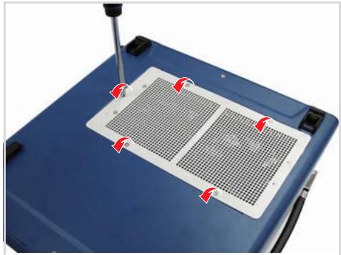
3. Loosen five screws, lift the fan tray carefully, then lay it on top of the chassis.
![Close-up of a blue industrial machine with a metal grate and screwdriver inserted, showing red arrows indicating force or adjustment points (no text or symbols visible)](.pxis-2508-manual-8/44978bb519d045cca3f8836b2c4bff0a34ccb0bf050d14be7a73a2b41c728b13.jpg)

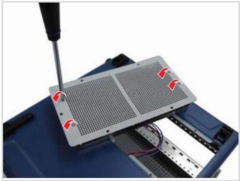
4. Loosen four screws to remove the fan tray cover.
![Close-up of a blue electronic device with a screwdriver inserted, showing a grid-patterned panel and wiring (no text or symbols visible)](.pxis-2508-manual-8/133327b625f93451f93b1add68a396a9a3ffac3906a92de19807a447736a8955.jpg)

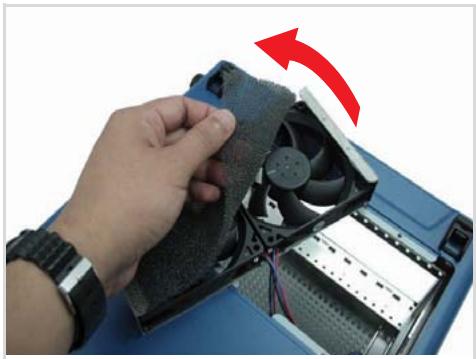
5. Take off the old air filter.

![Close-up of a hand holding a CPU fan with a red arrow indicating rotation (no text or symbols visible)](.pxis-2508-manual-8/4bd54878ab2a52139a984e408d131b3441df247485b612c26c6ed4f9a782452a.jpg)

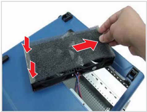
6. Peel the adhesive on both ends of the new air filter, then stick them on the fan tray edges. Stretch the filter to cover the whole fan tray length.
![Close-up of a hand holding a damaged black electronic device with red arrows indicating motion or damage (no text or symbols visible)](.pxis-2508-manual-8/36a790c712508f09c25bcf7e18b08ab62168fe29979d60443c405f51bbb7573c.jpg)

WARNING Make sure the fan blades do not come in contact with the air filter.

7. Replace the fan tray cover, then re-install the fan tray to the chassis.
8. Connect all cables, then turn on the system.

# Handling the Chassis

While the PXIS-2508/2558T is an ultra-portable testing system, it is recommended that you transport or carry the chassis using the handles. The handles are designed to carry the weight of the chassis for superior portability and balance.

# Handling Cables

Treat all cables with care. Do not over extend any cable to prevent internal breaking. All cables and plugs must be handled or connected properly.

# Cleaning the Exterior

Make sure that you turn the system off before cleaning the chassis exterior. Wipe the exterior with a clean cloth starting from areas that easily accumulate dust or dirt such as the area in and around the chassis and power supply air inlet apertures.

# Power Requirements

Make sure that the power cord is in good condition before plugging it into the system. You also need to check the reliability of the power source. The PXIS-2508/2558T power supply is capable of handling 100 V to 240 V AC within the 50 Hz to 60 Hz range. Do not connect the PXIS-2508/2558T on an already overloaded circuit.

# Important Safety Instructions

Read and follow all instructions marked on the product and in the documentation before operating the system. Retain all safety and operating instructions for future use.

▶ Read these safety instructions carefully.
- Keep this user’s manual for future reference.
The equipment should be operated in an ambient temperature between $0^{\circ}$ C to $50^{\circ}$ C.
The equipment should be operated only from the type of power source indicated on the rating label. Make sure the voltage of the power source is correct when connecting the equipment to the power outlet.
If the user's equipment has a voltage selector switch, make sure that the switch is set to the proper position for the area. The voltage selector switch is set at the factory to the correct voltage.
▶ For pluggable equipment, ensure they are installed near a socket-outlet that is easily accessible.
- Secure the power cord to prevent unnecessary accidents. Do not place anything over the power cord.
▶ If the equipment will not be in use for long periods of time, disconnect the equipment from the power outlet to avoid being damaged by transient over voltage.
▶ All cautions and warnings on the equipment must be noted.
▶ Keep this equipment away from humidity.
▶ Do not use this equipment near water or a heat source.
▶ Place this equipment on a stable surface when installing to prevent injury.
▶ Never pour any liquid into the product to prevent fire or electrical shock.

▶ Openings in the chassis are provided for ventilation. Do not block or cover these openings. Make sure there is adequate space around the system for ventilation when setting up the work area. Never insert objects of any kind into the ventilation holes.
▶ To avoid electrical shock, always unplug all power and modem cables from wall outlets before removing the system covers.
▶ The equipment must be serviced by authorized technicians when:

The power cord or plug is damaged.
▷ Liquid has penetrated the equipment.
▷ It has been exposed to moisture.
$\triangleright$ It is not functioning or does not function according to the user's manual.
▷ It has been dropped and damaged.
▷ It has an obvious sign of breakage.

▶ Never attempt to fix the equipment. For safety reasons, the equipment should only be serviced by qualified personnel.

# Warranty Policy

Thank you for choosing ADLINK. To understand your rights and enjoy all the after-sales services we offer, please read the following carefully.

1. Before using ADLINK's products please read the user manual and follow the instructions exactly. When sending in damaged products for repair, please attach an RMA application form which can be downloaded from:
http://rma.adlinktech.com/policy/RMA.doc

2. All ADLINK products come with a limited two-year warranty, one year for products bought in China:

The warranty period starts on the day the product is shipped from ADLINK's factory.
Peripherals and third-party products not manufactured by ADLINK will be covered by the original manufacturers' warranty.
For products containing storage devices (hard drives, flash cards, etc.), please back up your data before sending them for repair. ADLINK is not responsible for any loss of data.
Please ensure the use of properly licensed software with our systems. ADLINK does not condone the use of pirated software and will not service systems using such software. ADLINK will not be held legally responsible for products shipped with unlicensed software installed by the user.
For general repairs, please do not include peripheral accessories. If peripherals need to be included, be certain to specify which items you sent on the RMA Request & Confirmation Form. ADLINK is not responsible for items not listed on the RMA Request & Confirmation Form.

3. Our repair service is not covered by ADLINK's guarantee in the following situations:

▷ Damage caused by not following instructions in the User's Manual.
Damage caused by carelessness on the user's part during product transportation.
Damage caused by fire, earthquakes, floods, lightening, pollution, other acts of God, and/or incorrect usage of voltage transformers.
Damage caused by unsuitable storage environments (i.e. high temperatures, high humidity, or volatile chemicals).
▷ Damage caused by leakage of battery fluid during or after change of batteries by customer/user.
▷ Damage from improper repair by unauthorized ADLINK technicians.
▷ Products with altered and/or damaged serial numbers are not entitled to our service.
▷ This warranty is not transferable or extendible.
▷ Other categories not protected under our warranty.

4. Customers are responsible for shipping costs to transport damaged products to our company or sales office.

5. To ensure the speed and quality of product repair, please download an RMA application form from our company website: http://rma.adlinktech.com/policy. Damaged products with attached RMA forms receive priority.

If you have any further questions, please email our FAE staff: service@adlinktech.com.
[🔗 Link to the original document](.pxis-2508-manual-8/pxis-2508-manual-8.pdf)