# PXIS-2719

19-Slot Smart PXI Chassis with 700 W AC Power Suppl

User's Manual

Manual Rev. 2.00

Revision Date: July 30, 2008

Part No: 50-17029-1000

![The image displays a black circular background featuring a white recycling symbol composed of three arrows arranged in a clockwise triangular loop. Each arrow is stylized with three thin, parallel white lines running along the length of its shaft.](.pxis-2719-50-17029-1000-007/62d5eced66f92c502befc732d89211eef3d4c7369106f952a91bac60e20388b9.jpg)
Recycled Paper

Copyright 2008 ADLINK TECHNOLOGY INC.

All Rights Reserved.

# Disclaimer

The information in this document is subject to change without prior notice in order to improve reliability, design, and function and does not represent a commitment on the part of the manufacturer.

In no event will the manufacturer be liable for direct, indirect, special, incidental, or consequential damages arising out of the use or inability to use the product or documentation, even if advised of the possibility of such damages.

This document contains proprietary information protected by copyright. All rights are reserved. No part of this manual may be reproduced by any mechanical, electronic, or other means in any form without prior written permission of the manufacturer.

# Trademark Information

PXI is registered trademarks of PXI Systems Alliance. Other product names mentioned herein are used for identification purposes only and may be trademarks and/or registered trademarks of their respective companies.

# Getting service

Customer satisfaction is our top priority. Contact us should you require any service or assistance.

# ADLINK TECHNOLOGY INC.

Web Site http://www.adlinktech.com

Sales & Service service@adlinktech.com

Telephone No. +886-2-8226-5877

Fax No. +886-2-8226-5717

Mailing Address 9F No. 166 Jian Yi Road, Chungho City,

Taipei Hsien 235, Taiwan

# ADLINK TECHNOLOGY AMERICA, INC.

Sales & Service info@adlinktech.com

Toll-Free +1-866-4-ADLINK (235465)

Fax No. +1-949-727-2099

Mailing Address 8900 Research Drive, Irvine,

CA 92618, USA

# ADLINK TECHNOLOGY EUROPEAN SALES OFFICE

Sales & Service emea@adlinktech.com

Toll-Free +49-211-4955552

Fax No. +49-211-4955557

Mailing Address    Nord Carree 3, 40477 Düsseldorf, Germany

# ADLINK TECHNOLOGY SINGAPORE PTE LTD.

Sales & Service singapore@adlinktech.com

Telephone No. +65-6844-2261

Fax No. +65-6844-2263

Mailing Address 84 Genting Lane #07-02A,

Cityneon Design Center, Singapore 349584

# ADLINK TECHNOLOGY SINGAPORE PTE LTD.

# (INDIA Liaison Office)

Sales & Service india@adlinktech.com

Telephone No. +91-80-57605817

Fax No. +91-80-26671806

Mailing Address No. 1357, Ground Floor, "Anupama",

Aurobindo Marg JP Nagar (Ph-1)

Bangalore - 560078

# ADLINK TECHNOLOGY INC. (KOREA Liaison Office)

Sales & Service korea@adlinktech.com

Telephone No. +82-2-20570565

Fax No. +82-2-20570563

Mailing Address 4F, Kostech Building, 262-2,

Yangjae-Dong, Seocho-Gu,

Seoul, 137-130, South Korea

# ADLINK TECHNOLOGY (BEIJING) CO., LTD.

Sales & Service market@adlinkchina.com.cn

Telephone No. +86-10-5885-8666

Fax No. +86-10-5885-8625

Mailing Address Room 801, Building E, Yingchuangdongli

Plaza, No.1 Shangdidonglu,

Haidian District, Beijing, China

# ADLINK TECHNOLOGY (SHANGHAI) CO., LTD.

Sales & Service market@adlinkchina.com.cn

Telephone No. +86-21-6495-5210

Fax No. +86-21-5450-0414

Mailing Address Floor 4, Bldg. 39, Caoheting Science and

Technology Park, No.333 Qinjiang Road,

Shanghai, China

# ADLINK TECHNOLOGY (SHENZEN) CO., LTD.

Sales & Service market@adlinkchina.com.cn

Telephone No. +86-755-2643-4858

Fax No. +86-755-2664-6353

Mailing Address C Block, 2nd Floor, Building A1,

Cyber-tech Zone, Gaoxin Ave. 7.S,

High-tech Industrial Park S.,

Nanshan District, Shenzhen,

Guangdong Province, China

# Using this manual

# Audience and scope

This manual guides you when using the portable ADLINK PXI chassis. This manual is intended for system integrators, computer programmers, and hardware engineers with advanced knowledge of PXI/cPCI systems and PXI-based data acquisition.

# How this manual is organized

This manual is organized as follows:

Chapter 1 Introduction: This chapter introduces the PXIS-2719 chassis including its features, specifications, and package contents.

Chapter 2 Chassis Overview: This chapter presents the chassis layout, location of basic components, dimensions, and backplane information.

Chapter 3 Installation: This part describes the procedures on how to install a system controller and peripheral modules into the PXIS-2719. It also contains information on OS and driver installations and touch panel usage.

Chapter 4 Remote Management: The chapter illustrates the remote management features of the PXIS-2719.

Appendix A: The Appendix comes with a troubleshooting section for common installation problems and tells you how to maintain the PXIS-2719 chassis.

Important Safety Instructions: This section lists important safety reminders that you have to observe when using the chassis.

Warranty Policy: This presents the ADLINK Warranty Policy terms and coverages.

# Conventions

Take note of the following conventions used throughout the manual to make sure that you perform certain tasks and instructions properly.

NOTE Additional information, aids, and tips that help you perform particular tasks.

IMPORTANT Critical information and instructions that you MUST perform to complete a task.

WARNING Information that prevents physical injury, data loss, module damage, program corruption etc. when trying to complete a particular task.

# Table of Contents

# Table of Contents...... i

# List of Tables...... iii

# List of Figures ...... iv

# 1 Introduction ...... 1

1.1 Features.... 3
1.2 Specifications.... 4
1.3 Unpacking Checklist 7

# 2 Chassis Overview.... 9

2.1 Chassis Description 9

PXIS-2719 Front View 9
PXIS-2719 Back View 10
PXIS-2719 Left View 11
PXIS-2719 Right View 11
PXIS-2719 Top View 12
PXIS-2719 Bottom View 13

2.2 Chassis Dimensions 14

PXIS-2719 Dimension (Front) 14
PXIS-2719 Dimensions (Side) 14
PXIS-2719 Dimension (Bottom) 15

2.3 Backplane overview.... 16

Interoperability with CompactPCI 16
System Controller Slot 16
Star Trigger Slot 16
Peripheral Slots 17
Local Bus 17
Trigger Bus 18
System Reference Clock 18

# 3 Installation 19

3.1 Cooling Consideration 19
3.2 Rack Mounting.... 20
3.3 Hardware Installation 23

Selecting 10 Mhz Reference Clock Source ...... 23

Installing the System Controller 24

Installing Peripheral Modules 27

Powering Up the System 29

3.4 Software Installation.... 31

OS Installation 31

Install the Chassis Description File (chassis.ini) ...... 31

# 4 Remote Management.... 33

4.1 Installing the Monitor Utility 34

4.2 Monitoring the PXIS-2719.... 35

Using the Monitor Utility 35

Using the Monitoring/Control Function Library 39

# A Troubleshooting and Maintenance 49

A.1 Installation Problems.... 49

A.2 Basic Troubleshooting 50

A.3 Maintenance 52

Changing the Fan Filter 52

Handling the Chassis 55

Cleaning the Exterior 55

Power Requirements 55

# Important Safety Instructions.... 57

# List of Tables

Table 1-1: DC Output 4

Table 3-1: 10 MHz Reference Clock Settings 23

# List of Figures

Figure 2-1: PXI Bus Signal Routing .... 17

# 1 Introduction

![Front view of a beige AXI 800 microcontroller with visible ports and indicator lights (no readable text or symbols beyond branding)](.pxis-2719-50-17029-1000-007/bb72233b6ea401cb4c484b9b7127f828aced6894c2ec8f82289da29c65c5da28.jpg)

The ADLINK PXIS-2719 is a 3U PXI chassis with abundant advanced features. The PXIS-2719 is compliant with PXI and CompactPCI specifications and provides one system slot and eighteen peripheral slots. It is designed to meet or exceed the requirements of large capacity, wide operating temperature range, uniformity of heat dissipation and exceptional chassis weight and robustness.

The PXIS-2719 also offers an intelligent chassis control feature to manage the chassis status. Fan speed is automatically controlled according to inner temperature of chassis. DC voltages, fan speed, and inner temperature are monitored by the intelligent control board and can be exported to a remote computer via a standard RS-232 port.

ADLINK PXIS-2719 features an innovative cooling mechanism to provide superior heat dissipation capability. Four 68CFM fans are placed in the rear section of the chassis. Cool air is pulled in from the apertures on the bottom, flowed through PXI modules, and is exhausted to the rear side. With this new cooling mechanism, not only exceptional efficiency of heat dissipation, but also great uniformity for each PXI slot is delivered by the PXIS-2719 chassis.

![Cross-sectional diagram of a device showing internal components and airflow direction (no text or symbols)](.pxis-2719-50-17029-1000-007/3d09559a3ec04c63d1c549b237fbf91bccf8f6a9fb3b544e2fdb5ec508b90480.jpg)

The PXIS-2719 comes with an Industrial-grade 700 W AC power supply to provide reliable power to the system, as well as a BNC connector for an external 10 MHz reference clock input, front panel LEDs, and easy-access PXI/CompactPCI slots with card guides for convenient installation and use. It is designed to accommodate a 3-slot PXI controller. ADLINK PXI-3950/3920/3910 PXI controllers are highly recommended. With innovative features and robust design, the PXIS-2719 is your best choices of PXI platform for all your test and measurement requirements.

# 1.1 Features

▶ PXI Specification Rev. 2.2-compliant
Rack-mount 19-slot PXI chassis, equipped with one system slot and 18 PXI/CompactPCI peripheral slots
▶ Advanced forced-cooling mechanism for efficient and uniform heat dissipation
▶ External 10 MHz reference clock input with BNC connector
▶ 0°C to 55°C extended operating temperature range
▶ Intelligent chassis monitoring/control
▶ Automatic fan speed control
▷ Chassis status monitoring and exporting
▶ Remote chassis power on/off control
▶ 700 W industrial-grade AC power supply
▶ Power, temperature and fan monitoring LEDs

# 1.2 Specifications

PXIS-2719 complies with the PXI Specification Rev. 2.2 and accepts modules compliant with the CompactPCI and PICMG 2.0 specification

# Power Supply

AC Input

Input voltage range 90 to 264 VAC full range

Input voltage frequency 47 to 63 Hz

Input current rating 12 A for 115 VAC

6 A for 230 VAC

DC Output

Total DC power output 700W

<table><tr><td>VDC</td><td>Minimum</td><td>Maximum</td><td>Load Regulation</td><td>Line Regulation</td><td>Maximum Ripple &amp; Noise</td></tr><tr><td>+5V</td><td>2.5 A</td><td>50.0 A</td><td>±4%</td><td>±1%</td><td>60 mV</td></tr><tr><td>+12V</td><td>1.0A</td><td>32.0 A</td><td>±5%</td><td>±1%</td><td>100 mV</td></tr><tr><td>+3.3V</td><td>1.0A</td><td>45.0 A</td><td>±5%</td><td>±1%</td><td>60 mV</td></tr><tr><td>-12V*</td><td>0 A</td><td>4.5 A</td><td>±5%</td><td>±1%</td><td>100 mV</td></tr></table>

Table 1-1: DC Output

\* -12V is provided by an internal +12VDC to -12VDC converting board

# Cooling

Fans 4 sets of 68 CFM fans

Per-slot cooling capacity 25 W (verified by 55°C chamber test)

# Acoustic Emissions

Sound Pressure Level1 (dBA) (measured at operator position)

<table><tr><td>Minimum fan speed</td><td>49.7 dB</td></tr><tr><td>Maximum fan speed</td><td>57.7 dB</td></tr></table>

Tested in Accordance with ISO 7779:1999/Amd.1:2003(E)

Sound Power (dBA)

<table><tr><td>Minimum fan speed</td><td>59.8 dB</td></tr><tr><td>Maximum fan speed</td><td>69.1 dB</td></tr></table>

Tested in Accordance with ISO 7779:1999/Amd.1:2003(E)

# Physical

<table><tr><td>Number of PXI slots</td><td>19 (1 system slot + 18 peripheral slots)</td></tr><tr><td>Dimensions</td><td>444 mm (W) x 178 mm (H) x 455 mm (D)</td></tr><tr><td>Weight</td><td>13.4 kg (29.5 lbs)</td></tr></table>

# Operating Environment

<table><tr><td>Ambient temperature</td><td>0 to 55°C</td></tr><tr><td>Relative humidity</td><td>10 to 90%, noncondensing</td></tr></table>

# Storage Environment

<table><tr><td>Ambient temperature</td><td>-20 to 70°C</td></tr><tr><td>Relative humidity</td><td>10 to 90%, noncondensing</td></tr></table>

# Shock and Vibration

Functional shock

30 G, half-sine, 11 ms pulse duration

# Random Vibration

Operating

5 to 500 Hz, 0.31 Grms, 3 axes

Nonoperating

5 to 500 Hz, 2.46 Grms, 3 axes

# Certification

Safety

IEC 61010-1/EN 61010-1

Electromagnetic Compatibility

Emissions

EN 55011 Class A

Immunity

EN 61326-1

# CE Compliance

PXIS-719 meets the essential requirements of applicable European Directives, as amended for CE Marking, as follows:

Low-Voltage Directive (safety)

73/23/EEC

Electromagnetic Compatibility Directive (EMC)

9/336/EEC

# 1.3 Unpacking Checklist

Before unpacking, check the shipping carton for any damage. If the shipping carton and/or contents are damaged, inform your dealer immediately. Retain the shipping carton and packing materials for inspection. Obtain authorization from your dealer before returning any product to ADLINK.

Check if the following items are included in the package.

▶ PXIS-2719 Chassis, 3U 19-Slot Smart PXI Chassis with 700W AC Power Supply
▶ Power cords (110 V and 220 V)
▶ Filler panel kit for unused/reserved slots including one 3-slot panel and eighteen 1-slot panels
▶ Two spare fan filters for replacement
▶ ADLINK All-in-One CD
▶ User's Manual

# 2 Chassis Overview

This chapter illustrates each functional part of the PXIS-2719 and its dimensions. The PXI backplane in the PXIS-2719 is also described.

# 2.1 Chassis Description

# 2.1.1 PXIS-2719 Front View

![Standby/Power Switch\nAlarm Reset Button\nPower LED\nFan LED\nTemperature LED\nPX1\nFoot Stands\nSystem Slot\nPeripheral Slots](.pxis-2719-50-17029-1000-007/638f6a5f73428a8f2d2477956f4f7647284cb0703ca7dddca58f7820c31a5de1.jpg)

LED Indicators

<table><tr><td rowspan="2">LED</td><td colspan="3">Status</td></tr><tr><td>On</td><td>Off</td><td>Blinking</td></tr><tr><td>Power (Blue)</td><td>DC voltages are supplied normally.</td><td>No DC power is supplied.</td><td>5 V or 3.3 V exceeds ±7% range12 V or -12 V exceeds ±12% range</td></tr><tr><td>Fan (Green)</td><td>Fans are operating normally.</td><td>The system is off.</td><td>Any of the fans is operating in a speed lower than 500 RPM</td></tr><tr><td>Temp (Amber)</td><td>Chassis temperature is normal</td><td>The system is off.</td><td>Chassis temperature exceeds 50°C</td></tr></table>

# Alarm Reset Button

The alarm reset button enables you to stop the chassis alarm buzzer during an error or critical system event. To stop the alarm, press the alarm reset button.

# 2.1.2 PXIS-2719 Back View

![Outlet Apertures\nPower Supply Fan Outlet\nAC Power Connector\nMain Power Switch\nRemote Monitoring Port\n10 MHz Reference Clock Input](.pxis-2719-50-17029-1000-007/fb289433d289a31d4fa96bb9b3fc4b1e42c68e09de333e8ae477ffd6938d5ac2.jpg)

# 2.1.3 PXIS-2719 Left View

![Handle\nScrew Holes for Rack-mounting Kit](.pxis-2719-50-17029-1000-007/4175ecc85788ca963dd0eb22ea1aad71ce7256f4e694b49def07562e2f151d34.jpg)

# 2.1.4 PXIS-2719 Right View

![Rubber Pads\nScrew Holes for Rack-mounting Kit](.pxis-2719-50-17029-1000-007/30113809b8851366dc5e1619444a0f7934644e8aebc6ed5c005f3dab80b3d013.jpg)

2.1.5 PXIS-2719 Top View
![Empty whiteboard frame with blue horizontal bars at both ends (no text or symbols)](.pxis-2719-50-17029-1000-007/79c608f2e1397ceefb6ff7d324ce0852eed6f90411af295455effdbc2faed5df.jpg)

2.1.6 PXIS-2719 Bottom View
![Based on the provided image, here is the description of the labeled blocks and their connections:\n\n**Labeled Blocks:**\n*   **Intake Apertures**\n*   **Foot Stands**\n\n**Connections:**\n*   **Intake Apertures:** A single vertical line extends upward from this label to point directly at the large, perforated metal panel located at the top of the diagram.\n*   **Foot Stands:** A network of lines radiates from this label to connect to the four corner brackets of the unit. Specifically:\n    *   A line extends diagonally upward to the top-left corner bracket.\n    *   A line extends diagonally upward to the top-right corner bracket.\n    *   A line extends diagonally downward to the bottom-left corner bracket.\n    *   A line extends diagonally downward to the bottom-right corner bracket.](.pxis-2719-50-17029-1000-007/8bcac9f4bfd44187b11adeb8f0298d5378a9dd740ba47baa89c43c088cd90e29.jpg)

# 2.2 Chassis Dimensions

# 2.2.1 PXIS-2719 Dimension (Front)

![ADLEK\n177.8 (7)\n444.4 (17.5)\n10 (.4)](.pxis-2719-50-17029-1000-007/a3912d6269e0ba754f048713859611ae77b1d267cf44d1645ba772acf736d3a7.jpg)

# 2.2.2 PXIS-2719 Dimensions (Side)

![56 (2.2)\n60.9 (2.4)\n401 (15.8)\n455 (17.9)\n14 (.6)](.pxis-2719-50-17029-1000-007/1b7d6db791134e8af9a116fe13ea7191422e25d2b551fe8a9fa7f408d5e25be2.jpg)

2.2.3 PXIS-2719 Dimension (Bottom)
![408.8 (16.1)\n28.5 (1.1)\n403 (15.9)](.pxis-2719-50-17029-1000-007/036728a59510a9f9446c9023fc74791c15bb8f6b8dd258e660eee64608660a65.jpg)

# 2.3 Backplane overview

# 2.3.1 Interoperability with CompactPCI

PXIS-2719 is designed to be used with both PXI-compatible products and standard CompactPCI products. Its backplanes is compliant with PXI Specification Rev. 2.2.

The signals on the P1 connector of the backplane meet the requirements of the CompactPCI specification for both the peripheral and system modules.

The PXI-specific signals are located on P2. Only the signals that are reserved or not used in the CompactPCI 64-bit specification are found on PXI-specific signals. Therefore, peripheral modules that meet the requirements of the CompactPCI 64-bit specification will function in the PXIS-2719.

# Note:

Do NOT install CompactPCI peripheral modules which operate with rear I/O modules in PXIS-2719 due to the possible conflict between rear I/O signals and PXI-specific signals on J2.

# 2.3.2 System Controller Slot

The System Controller slot is Slot 1 of the chassis as defined by the PXI specification. The PXIS-2719 chassis can accommodate a PXI system controller that occupies up to 3 slots width. As defined in the PXI specification, two controller expansion slots allow the controller to expand to the left to prevent the controller from using up peripheral slots.

# 2.3.3 Star Trigger Slot

The Star Trigger (ST) slot is Slot 2. This slot has dedicated trigger lines between ST slot itself and slots 3-15. The star trigger functionality is intended to provide a precise trigger signal to the peripheral modules by installing a specific star trigger controller module in the ST slot. The star trigger slot can be also used as a general peripheral slot if you do not need the star trigger functionality.

# 2.3.4 Peripheral Slots

There are 18 peripheral slots in PXIS-2719 (including the Star Trigger controller slot). Each peripheral slot can accommodate a 3U PXI/CompactPCI peripheral module.

Note:

DO NOT install a 3U CompactPCI module with rear I/O function in the PXIS-2719 chassis.

![Based on the provided image, here is an accurate and concise description of the flowchart:\n\n**Labeled Blocks:**\n*   **10 MHz Clock and Buffer Circuitry** (Top center)\n*   **System Controller** (Far left vertical bar)\n*   **Star Trigger Controller** (Vertical bar, labeled '2' at the bottom)\n*   **Peripheral Slot** (Vertical bars, repeated 16 times, labeled '3' through '18' at the bottom)\n*   **Bridge** (Small boxes at the very bottom, appearing twice)\n\n**Connections:**\n*   **Clock Distribution:** Multiple lines extend downward from the **10 MHz Clock and Buffer Circuitry** to connect to the top of every vertical block (**Star Trigger Controller** and all **Peripheral Slot** blocks).\n*   **System Control:** Lines extend from the **System Controller** to the right, connecting into the vertical blocks.\n*   **Local Bus:** Double-headed horizontal arrows labeled **Local Bus** connect each adjacent vertical block (between the Star Trigger Controller and the first Peripheral Slot, and between every subsequent Peripheral Slot).\n*   **Main Bus:** Large horizontal double-headed arrows run along the bottom of the diagram, labeled **PXI Trigger Bus Segment and PCI Bus Segment**.\n*   **Bridges:** Arrows connect the bottom bus segments to the two **Bridge** blocks located below them.](.pxis-2719-50-17029-1000-007/4efb67be418144091b6c0aa4f933da78b5da31d8ff4e1c7377ed6772a29bc169.jpg)

Figure 2-1: PXI Bus Signal Routing

# 2.3.5 Local Bus

The local bus on a PXI backplane is a daisy-chained bus that connects each peripheral slot with its adjacent peripheral slots to the left and right. Each local bus has 13 lines and can transmit analog or digital signals between modules. It can also provide a high-speed side-band communication path that does not affect the PCI bandwidth.

In accordance with the PXI specification, the local bus connects all adjacent slots except slots 1 and 2.

# 2.3.6 Trigger Bus

The trigger bus is a 8-lines bus that connects all PXI slots in the same PCI segment. The trigger bus can be used to provide inter-module synchronization mechanism. PXI modules can transmit trigger or clock signals to one another through trigger bus, allowing precisely timed responses to asynchronous external events the system is monitoring or controlling.

# 2.3.7 System Reference Clock

PXIS-2719 supplies the PXI 10MHz system reference clock (PXI\_CLK10) to each peripheral slot for inter-module synchronization. An independent buffer (having source impedance matched to the backplane and a skew of less than 1 ns between slots) drives the clock signal generated from a high-precision oscillator to each peripheral slot.

This common reference clock signal can be used to synchronize multiple modules in a PXI chassis.

# 3 Installation

This chapter describes the procedures to set up the PXI chassis, install the PXI system controller and peripheral modules, and power up the system. It also provides information on cooling considerations, rack-mounting, and installing proper driver/software.

# 3.1 Cooling Consideration

The PXIS-2719 implements the forced air-cooling mechanism to provide efficient and uniform heat dissipation. The cold air is intaken through filters and fan inlets on the bottom of the chassis and the hot air is exhausted though the outlet apertures in the upper rear of the chassis. When you place the PXIS-2719 on a bench top, providing adequate clearance for the inlet apertures is necessary. And for better cooling efficiency, keep the feet stand if possible.

When rack mounting the PXIS-2719, at least 1U (44.5 mm/1.75 in.) clearance below the intake apertures is required. And please also keep other object or equipment at a minimum of 76.2 mm (3 in.) away from the outlet apertures in the rear region of the chassis.

# Note:

The cooling design of PXI-2719 allows an air flow from bottom to the rear of chassis though PXI modules. To maintain an expected air flow, please always install filler panels for unused slots. The filler panels can be found in the package of the chassis.

![Cross-sectional diagram of a 3D printer or scanner device showing internal components and airflow direction (no text or symbols)](.pxis-2719-50-17029-1000-007/ea54b229549b1724c910feea34f3adf2466761d6c31d9429e55b8574f3e304d1.jpg)

# 3.2 Rack Mounting

ADLINK provides an optional rack-mount kit to install the PXIS-2719 into a rack. The rack-mount kit can flexibly recess the PXIS-2719 in the rack to accommodate external mechanical parts on the front side, such as cables and mass interconnect modules.

![Technical diagram of a rack-mounted server or server unit with numbered components for identification.](.pxis-2719-50-17029-1000-007/d934e7992e4904b7c338a12b56a4b23166e502ca01de60774a3a5e2d87603e8e.jpg)

To assemble the rack-mount kit and mount the PXIS-2719 in a rack:

1. Remove the handle on the left side (①).

1-1. Open the screw covers of the handle using a screw-driver

![Close-up of a black tool with a red square annotation highlighting a specific area, placed on a metallic surface (no text or symbols visible)](.pxis-2719-50-17029-1000-007/ac07ebb2292d9c6cd86d8c49ba0e93391bae3f022d9f3de8f2495835ae74ea03.jpg)

# 1-2. Loosen the handle screws

![Close-up of a screwdriver inserted into a square mechanical component, with a red circle highlighting the component area (no text or symbols visible)](.pxis-2719-50-17029-1000-007/1446ed845991505f020cb5b64eb8bcee42912d3b5777c8b358fc92102a7ed7e9.jpg)

2. Remove the four rubber foot stands on the right side (②).
3. Install the handle (③) to the mounting bracket (④) using two M4 screws supplied.
4. Install the mounting brackets (④) to the side of the chassis using two M4 screws supplied. You can adjust the position of mounting brackets to recess the chassis in the rack at any distance.
5. Install the chassis in the rack using eight screws (not included).

# 3.3 Hardware Installation

# 3.3.1 Selecting 10 Mhz Reference Clock Source

The 10 MHz reference clock is an important mechanism in PXI specification for inter-module synchronization. PXI modules which have phase-locker loop circuit can lock the 10 MHz reference clock to generate an in-phase timebase.

The PXIS-2719 PXI chassis allows users to select the source of 10 MHz reference clock as

▶ Built-in accurate 10 MHz oscillator
▶ External 10 MHz clock through a BNC connector
▶ PXI\_CLK10\_IN pin on the star trigger slot

You can set the source of 10 MHz reference clock by a DIP switch on the front side of backplane. Please refer to Table 3-1 for the setting.

![Close-up of an electronic circuit board with a highlighted component (red circle) and alphanumeric labels, no readable text or symbols on the main components.](.pxis-2719-50-17029-1000-007/3654cb858f3e444a5f381b5a8a4e444000fe3729c0d3748145a1f2dd3e8e7926.jpg)

<table><tr><td></td><td>P1</td><td>P2</td><td>P3</td></tr><tr><td>Built-in 10 MHz oscillator (default)</td><td>OFF</td><td>OFF</td><td>ON</td></tr><tr><td>External 10 MHz clock input</td><td>OFF</td><td>OFF</td><td>OFF</td></tr><tr><td>PXI_CLK10_IN of star trigger slot</td><td>OFF</td><td>ON</td><td>OFF</td></tr></table>

Table 3-1: 10 MHz Reference Clock Settings

# 3.3.2 Installing the System Controller

The PXIS-2719 comes with a system controller slot that supports a PXI system controller of 3-slot width. We recommend the following system controllers for use with the PXIS-2719:

▶ ADLINK PXI-3950 Core 2 Duo PXI controller
▶ ADLINK PXI-3920 Pentium M PXI controller
▶ ADLINK PXI-3910 Celeron M PXI controller

To install the system controller:

1. Make sure that the CPU, memory module(s), and storage device(s) are properly installed on the system controller.
2. Locate the system controller slot (Slot 1).

![ADLINK\nCE\nPXi](.pxis-2719-50-17029-1000-007/c568543e538b3a652feaa96ae59f0fc3749df86226ce3d5f0e06ccd27f13cede.jpg)

3. Push down (loosen) the system controller module's ejector/injector handle.
4. Align the module's top and bottom edges to the card guides, then carefully slide the module into the chassis.

![Interior view of an ADLINK industrial control module with visible wiring and ports (no readable text or symbols)](.pxis-2719-50-17029-1000-007/5404b8dc09de31ac323159d61bd54d89952c6422fa4fd9e281c5657d9bfb16e3.jpg)

5. Pull up the ejector/injector handle until the module is properly connected to the chassis backplane.

![Front view of an ADLINK industrial control module with visible RAM slots and connected ports (no readable text or symbols)](.pxis-2719-50-17029-1000-007/ca3f28b750a3ca4fa71167268106b69e0d4a707a417262941b99e0bb766fccf7.jpg)

6. Fasten the screws on the module front panel, then connect all devices to the system controller.

![ADLINK\nADLINK\nFXI](.pxis-2719-50-17029-1000-007/3eedd1e2107e5ff68e06b431e6f2e42b2559c974ec4fda689d614b561ecaaec2.jpg)

# 3.3.3 Installing Peripheral Modules

The PXIS-2719 supports up to eighteen PXI/CompactPCI peripheral modules, including a star trigger module.

# Note:

DO NOT install a 3U CompactPCI module with rear I/O function in the PXIS-2719 chassis.

To install a peripheral module:

1. Select an available peripheral slot (slot 2 to 19)
2. Push down (loosen) the peripheral module's ejector/injector handle, then align the module's top and bottom edges to the card guides.
3. Carefully slide the modules into the chassis.

![ADLINK\nADLINK\nADLINK\nPBI-3050\nPXI\n③ ④ ⑤ ⑥ | ⑦ ⑧ ⑨ 10](.pxis-2719-50-17029-1000-007/c5642e8ebc4b1876bfd5e03a84fdae617ca4b06fe504334e2d3db42e65fd05d3.jpg)

4. Pull up the ejector/injector handle until the modules is properly connected to the chassis backplane.

![Close-up of an ADLINK industrial control module with visible circuit boards and connectors (no readable text or symbols)](.pxis-2719-50-17029-1000-007/07872f35cb043821fc39f0ca28e3dc4b17bc608faca55cdec078b19b04709bb2.jpg)

5. Fasten the screws on the module's front panel.

![Close-up of an ADLINK industrial control panel with visible circuit board and connectors, no readable text or symbols on the main components.](.pxis-2719-50-17029-1000-007/c8fc8bf6ac2ae954bc262e8645e27470326db891e3318df4ebf8f74c84f11006.jpg)

6. Repeat step 1 to 5 to install another PXI peripheral module.

# Note:

To get better efficiency of heat dissipation, after installing all PXI modules, please install filler plates for unused slots if exists.

# 3.3.4 Powering Up the System

The PXIS-2719 is equipped with a 90 VAC to 264 VAC universal power supply unit that does not require input voltage selection.

To power on the chassis, complete the following steps:

1. Connect one end of the supplied power cable to the power connector located at the rear side of the chassis.

![Main Power\nSwitch\nAC Power\nConnector](.pxis-2719-50-17029-1000-007/2cfe2177eaa0fac03583e209bfb7076f2df57859ecd8d8295017f096715180ff.jpg)

2. Plug the other end of the AC power cord to a properly grounded wall socket or power strip.
3. Switch the main power switch to the ON (I) position.
4. Push the standby power switch. The Power LED (blue) lights up immediately, and Fan LED (green) and Temperature LED (amber) also light up 3 seconds later.

![Standby\nPower Switch\nADLINK\nPXI](.pxis-2719-50-17029-1000-007/fccf62b4ddf05339b7674d4ddfaa37b9317bf3692b65f7079c5b6dc91d436676.jpg)

To power off the chassis, complete the following steps

1. Push the standby power switch. The Power LED (blue), Fan LED (green) and Temperature LED (amber) turn off immediately.
2. And/or switch the main power switch to the OFF (O) position.

# Note:

To protect the PXI modules in the chassis, a frequent ON/STANDBY switch is not allowed. After you switch the standby power switch, please wait for 3 seconds before operating another ON/STANDBY switch.

# 3.4 Software Installation

# 3.4.1 OS Installation

Install the operating system that your system controller supports. For more information, refer to the documentation provided by the operating system vendor and the system controller manual. Most operating systems require installation from a floppy or optical disk drive. These devices must be configured, installed, and tested with the supplied drivers before attempting to install a new operating system. Consult the release notes and installation documentation provided by the operating system vendor for documentation discrepancies and/or compatibility issues, problems, and solutions.

# 3.4.2 Install the Chassis Description File (chassis.ini)

To allow inter-operability of PXI platform and modules from different vendors, the PXI specification requires hardware description files in ASCII text format to describe the hardware characteristics. System integrators can use the hardware description files to configure the system with various PXI controller, PXI chassis, and PXI modules.

ADLINK provides a complete list of the chassis description file (chassis.ini) for PXI chassis. The chassis description file can be found in

X:\Driver Installation\PXI Platform\PXI Platform Description\
(X: is the CD-ROM drive where you placed the ADLINK All-in-One CD). A simple how-to document is also exists in the directory to illustrate the procedures of using the chassis description file with third-party software to build a PXI-based system.

# 4 Remote Management

The PXIS-2719 chassis provide an advanced remote monitoring and control function. The chassis status, including internal temperature, fan speed, and DC voltages, are exported via a standard RS-232 port located in the rear side allowing you to monitor the system on a remote computer. You may also use a remote computer to turn the system on or off through the monitoring port by sending software commands.

![Diagram of an electronic device rear panel with labeled ports and connectors, including a fan, capacitor, and USB port.](.pxis-2719-50-17029-1000-007/69d7c9e48dec596d1bc9b1dadb91e05cc751869030498f9025719426d7a5ff93.jpg)

Remote
Monitoring Port

To remotely monitor and control the PXIS-2719, you need to connect the remote monitoring port to a remote computer using a standard RS-232 cable.

# Note:

The remote monitor port is Rx-Tx/Tx-Rx crossed. You need to use a RS-232 cable which is Rx-Rx/Tx-Tx connected for the remote monitoring function.

# 4.1 Installing the Monitor Utility

You can find a setup file to install the remote monitoring utility and function library in ADLINK All-in-One CD.

To install the monitoring utility:

1. Connect a USB CD-/DVD-ROM drive to the system controller.
2. Place the ADLINK All-in-Once CD in the optical drive.
3. Locate the monitoring utility in this folder:

X:\Driver Installation\PXI Platform\PXI chassis\PXIS-2719\RemoteMon\

(where X: denotes your CD-ROM drive)

4. Double-click on the Setup.exe file to begin installation.

# 4.2 Monitoring the PXIS-2719

# 4.2.1 Using the Monitor Utility

ADLINK provides a GUI program (PXISRemoteMonUtil.exe) to monitor the status of PXIS-2719 by a remote computer.

To monitor the system using the monitor utility:

1. Make sure you have proper connection between remote monitoring port of PXIS-2719 and a remote computer.
2. Launch the PXISRemoteMonUtil.exe on the remote computer.
3. Select the COM port on the remote computer connected to the PXIS-2719 (COM1, for example).

![ADLINK PXI Chassis Remote Mon. Utility\nCOM Port\nCOM1\nCOM1\nCOM2\nCOM3\nCOM4\nCOM5\nCOM6\nCOM7\nCOM8\nT1: 0\nT2: 0\nFan Speed (RPM)\nF1: 0\nF2: 0\nF3: 0\nF4: 0\nF5: 0\nF6: 0\nInitialize RUN STOP\nADLINK TECHNOLOGY INC.\nDC Voltage (V)\n12V: 0\n5V: 0\n3.3V: 0\n-12V: 0\nFan Speed Control\nAuto Maximum](.pxis-2719-50-17029-1000-007/94f7a6826acbf2e3ac0d830596f272ebf14bcb9bb73cf3d1f5f435a0e5597cde.jpg)

4. Click Initialize to initialize the COM port. If the COM port is successfully initialized, the RUN button is enabled.

![ADLINK PXI Chassis Remote Mon. Utility\nCOM Port\nCOM1\nInitialize\nRUN\nSTOP\nChassis Status\nPower On/Off\nChassis Temperature (degree)\nT1: 0\nT2: 0\nFan Speed (RPM)\nF1: 0\nF2: 0\nF3: 0\nF4: 0\nF5: 0\nF6: 0\nADLINK\nTECHNOLOGY INC.\nDC Voltage (V)\n12V: 0\n5V: 0\n3.3V: 0\n-12V: 0\nFan Speed Control\nAuto Maximum](.pxis-2719-50-17029-1000-007/1f6294d58f857ee76a1774986063a836b5f9b9b0cf93d4d89bedea816304cfd1.jpg)

5. Click the RUN to display the chassis temperature, fan speed, and DC voltages. These values automatically update.

![ADLINK PXI Chassis Remote Mon. Utility\nCOM Port\nCOM1\nInitialize\nRUN\nSTOP\nChassis Status\nPower On/Off\nON\nChassis Temperature (degree)\nT1: 25 Normal\nT2: 22 Normal\nDC Voltage (V)\n12V: 12 Normal\n5V: 5.1 Normal\n3.3V: 3.4 Normal\n-12V: -12 Normal\nFan Speed (RPM)\nF1: 3200 Normal\nF2: 3100 Normal\nF3: 3200 Normal\nF4: 3100 Normal\nF5: 0 Disabled\nF6: 0 Disabled\nFan Speed Control\nAuto Maximum](.pxis-2719-50-17029-1000-007/8ddd471ac608ad35c7d0d89f460cec8e2e9eb956c8af1acbbffb585b25be8109.jpg)

6. The Fan Speed Control can be set as Auto (automatically control fan speed according to internal temperature) or Maximum (force the fans to operate in full speed).

![ADLINK PXI Chassis Remote Mon. Utility\nCOM Port\nCOM1\nInitialize\nRUN\nSTOP\nChassis Status\nPower On/Off\nON\nChassis Temperature (degree)\nT1: 25 Normal\nT2: 22 Normal\nDC Voltage (V)\n12V: 11.9 Normal\n5V: 5.1 Normal\n3.3V: 3.4 Normal\n-12V: -12.1 Normal\nFan Speed (RPM)\nF1: 4700 Normal\nF2: 4700 Normal\nF3: 4800 Normal\nF4: 4900 Normal\nF5: 0 Disabled\nF6: 0 Disabled\nFan Speed Control\n○ Auto ○ Maximum](.pxis-2719-50-17029-1000-007/d0af1c168e1e34273401dea34be6f28c12e7496ff61976d10be53a137ff4c3c9.jpg)

7. Click STOP to stop monitoring.

# 4.2.2 Using the Monitoring/Control Function Library

The monitoring/control function library can be used to create a customized program that would monitor and control the PXIS-2719. Refer to the data structure and function library below.

# Data Structure

In the library, a data structure is defined to describe the chassis status.

```lisp
typedef struct tagChassisStatus
{
    BYTE    PowerStatus

    //Fan status and RPM
    BYTE    Fan1Status;
    BYTE    Fan2Status;
    BYTE    Fan3Status;
    BYTE    Fan4Status;
    BYTE    Fan5Status;
    BYTE    Fan6Status;
    float    Fan1RPM;
    float    Fan2RPM;
    float    Fan3RPM;
    float    Fan4RPM;
    float    Fan5RPM;
    float    Fan6RPM;

    //Temperature sensor status and reading in degree centigrade
    BYTE    Temp1Status;
    BYTE    Temp2Status;
    float    Temp1Reading;
    float    Temp2Reading;

    //DC status and reading
    BYTE    DC1Status;
    BYTE    DC2Status;
    BYTE    DC3Status;
    BYTE    DC4Status;
    float    DC1Reading;
    float    DC2Reading;
    float    DC3Reading;
```

```txt
float DC4Reading;
BYTE Reserve1;
BYTE Reserve2;
} ChassisStatus;
```

The variables in the data structure are illustrated below.

<table><tr><td>Variable</td><td>Description</td><td>Type</td><td>Value</td></tr><tr><td>PowerStatus</td><td>Power On/Off status</td><td>BYTE</td><td>0: Off1: On</td></tr><tr><td>Fan1Status</td><td>Fan#1 operating status</td><td>BYTE</td><td rowspan="6">0: Normal1: Abnormal2: Disabled3: Stopped</td></tr><tr><td>Fan2Status</td><td>Fan#2 operating status</td><td>BYTE</td></tr><tr><td>Fan3Status</td><td>Fan#3 operating status</td><td>BYTE</td></tr><tr><td>Fan4Status</td><td>Fan#4 operating status</td><td>BYTE</td></tr><tr><td>Fan5Status</td><td>Fan#5 operating status</td><td>BYTE</td></tr><tr><td>Fan6Status</td><td>Fan#6 operating status</td><td>BYTE</td></tr><tr><td>Fan1RPM</td><td>Fan#1 speed in RPM</td><td>float</td><td rowspan="6">RPM value</td></tr><tr><td>Fan2RPM</td><td>Fan#2 speed in RPM</td><td>float</td></tr><tr><td>Fan3RPM</td><td>Fan#3 speed in RPM</td><td>float</td></tr><tr><td>Fan4RPM</td><td>Fan#4 speed in RPM</td><td>float</td></tr><tr><td>Fan5RPM</td><td>Fan#5 speed in RPM</td><td>float</td></tr><tr><td>Fan5RPM</td><td>Fan#6 speed in RPM</td><td>float</td></tr><tr><td>Temp1Status</td><td>Temperature sensor #1 status</td><td>BYTE</td><td rowspan="2">0: Normal1: Abnormal</td></tr><tr><td>Temp2Status</td><td>Temperature sensor #2 status</td><td>BYTE</td></tr><tr><td>Temp1Reading</td><td>Reading of temperature sensor#1 in °C</td><td>float</td><td rowspan="2">Temperature value</td></tr><tr><td>Temp1Reading</td><td>Reading of temperature sensor#2 in °C</td><td>float</td></tr><tr><td>DC1Status</td><td>DC 12 V status</td><td>BYTE</td><td rowspan="4">0: Normal1: Abnormal</td></tr><tr><td>DC2Status</td><td>DC 5 V status</td><td>BYTE</td></tr><tr><td>DC3Status</td><td>DC 3.3 V status</td><td>BYTE</td></tr><tr><td>DC4Status</td><td>DC -12 V status</td><td>BYTE</td></tr><tr><td>DC1Reading</td><td>DC 12 V voltage reading</td><td>float</td><td rowspan="4">Voltage value</td></tr><tr><td>DC2Reading</td><td>DC 5 V voltage reading</td><td>float</td></tr><tr><td>DC3Reading</td><td>DC 3.3 V voltage reading</td><td>float</td></tr><tr><td>DC4Reading</td><td>DC -12 V voltage reading</td><td>float</td></tr></table>

# Function Reference

# InitCOM

# Description

Initializes the remote computer COM port connected to the remote monitoring port of the PXIS-2719.

# Syntax

HANDLE InitCOM(LPCSTR com)

# Parameter

com A string denotes the COM port. Can be COM1 \~ COM8.

# Return Value

A handle to the initialized COM port. If the function returns NULL, the initialization of COM port failed.

# Example

```txt
HANDLE hCOM;
hCOM= InitCOM("COM1");
```

# GetChassisStatus

# Description

Gets the chassis status and stores the status in a ChassisStatus structure. You can invoke this function periodically to update the chassis status.

# Syntax

BOOL GetChassisStatus(HANDLE hCom, ChassisStatus\* Status)

# Parameters

hCom The initialized COM port.

Status ChassisStatus data structure that stores the chassis status

# Return Value

TRUE if the function succeeded. FALSE if the function failed.

# Example

```txt
ChassisStatus status;
BOOL ret;
ret = GetChassisStatus(hCom, &status);
```

# SetChassisPowerOn

# Description

Powers on the PXIS-2719.

# Syntax

BOOL SetChassisPowerOn (HANDLE hCom)

# Parameter

com The initialized COM port.

# Return Value

TRUE if the function succeeded. FALSE if the function failed.

# Example

```txt
BOOL ret;
ret= SetChassisPowerOn (hCom);
```

# SetChassisPowerOff

# Description

Powers off the PXIS-2719. You should shut down the system controller via the operating system before turning off the chassis power.

# Syntax

BOOL SetChassisPowerOff (HANDLE hCom)

# Parameter

com The initialized COM port.

# Return Value

TRUE if the function succeeded. FALSE if the function failed.

# Example

```javascript
BOOL ret;
ret= SetChassisPowerOff (hCom);
```

# SetFanSpeedMax

# Description

Set fan speed control as Max mode (force the fans to operate in full speed)

# Syntax

BOOL SetFanSpeedMax (HANDLE hCom)

# Parameter

com: An initialized COM port

# Return Value

TRUE if the function succeeded.

FALSE if the function failed.

# Example

```javascript
BOOL ret;
ret = SetFanSpeedMax (hCom);
```

# SetFanSpeedAuto

# Description

Set fan speed control as Auto mode (automatically control fan speed according to internal temperature)

# Syntax

BOOL SetFanSpeedAuto (HANDLE hCom)

# Parameter

com: An initialized COM port

# Return Value

TRUE if the function succeeded.

FALSE if the function failed.

# Example

```javascript
BOOL ret;
ret = SetFanSpeedAuto (hCom);
```

# CloseCOM

# Description

Closes the initialized COM port.

# Syntax

BOOL CloseCOM(HANDLE hCom)

# Parameter

com The initialized COM port.

# Return Value

TRUE if the function succeeded. FALSE if the function failed.

# Example

```txt
BOOL ret;
ret = CloseCOM (hCom);
```

# Appendix A Troubleshooting and Maintenance

This chapter describes basic troubleshooting techniques, as well as instructions of the maintenance of PXIS-2719 chassis.

# A.1 Installation Problems

Failure to start the system usually results from incorrect installation of the system controller, peripheral modules, and other components. Go through the following checklist before you start up the system.

▶ The system controller is properly installed and secured.
▶ All peripheral modules are properly seated on the slots.
▶ All cables are properly connected to the system controller/peripheral modules.
▶ All peripheral modules installed are compatible for use in the chassis.
The power cord is properly plugged into the chassis power connector and power outlet/wall socket/power strip.

If the system fails to turn on even after all installation conditions are met, remove all peripheral modules that you installed, then try again. If the system turns on properly, try installing one peripheral module at a time, then test if the system will power-up. You may also try installing the modules into different slots until you get the desired result.

# A.2 Basic Troubleshooting

<table><tr><td>Problem</td><td>What to Do</td></tr><tr><td>System fails to power up</td><td>▶ Check if the power cord is properly plugged into the chassis power connector and wall socket/power strip. ▶ Check if the wall socket/power strip is live. ▶ Check if the main power switch at the back of the chassis is turned on. ▶ Make sure the standby power button at the chassis front panel is turned on.</td></tr><tr><td>There is no video output in the external display</td><td>▶ Check if your external display is functioning. ▶ Check your display settings and make sure you enable external video.</td></tr><tr><td>Power LED (blue) is blinking</td><td>▶ Make sure there is no short circuit caused by your PXI modules. Remove all PXI modules (PXI controller and peripheral modules) and check if the condition remains. ▶ If the condition remains, contact you dealer for further assistance.</td></tr><tr><td>Fan LED (green) is blinking</td><td>▶ Check if any object blocks the fan and makes it stopped. ▶ If the condition remains after clearing the object, contact you dealer for further assistance.</td></tr><tr><td>Temperature LED (amber) is blinking</td><td>▶ Check if there is a smooth air flow from the outlet apertures. If not, check if adequate clearance for the inlet apertures is provided.▶ If the temperature of exhausted air is normal (below 50 degrees centi-grade) but the temperature LED is still blinking, contact you dealer for further assistance.</td></tr></table>

# A.3 Maintenance

# Changing the Fan Filter

The air inlet fans installed at the bottom of the chassis comes with a filter to prevent dirt and dust from entering the chassis. You need to periodically replace the air filter to maintain good chassis airflow.

To change the fan filter:

1. Turn off the chassis, then disconnect all cables connected to the chassis, system controller, and peripheral modules.
2. Lay the chassis upside down in a flat and stable surface.
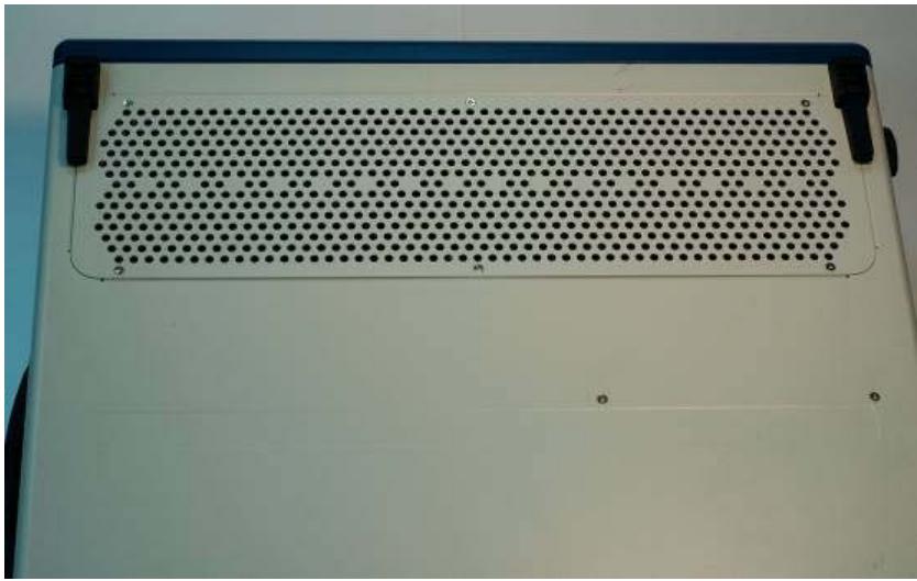
![Close-up of a white plastic panel with a perforated metal grille and mounting tabs (no text or symbols visible)](.pxis-2719-50-17029-1000-007/2271cf780c0933f92a260a948e116674bfba0ef8f8d9d05647ddcd29912d4516.jpg)

3. Remove the rubber pad of foot-stand. And loosen the screws for both foot stands.
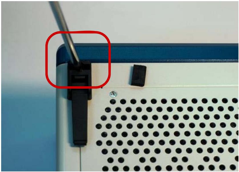
![Close-up of a white electronic device with black connectors and a perforated panel, no visible text or symbols.](.pxis-2719-50-17029-1000-007/f42fae0f79a0b7e62b3a39271a64bc3ccf20e2814351347ce762c95d4df328a6.jpg)

4. Loosen the six screws to remove the metal plate for inlet apertures.
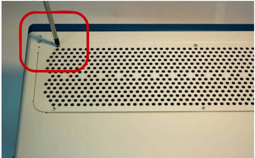
![Close-up of a perforated metal panel with a red annotation highlighting a specific area (no text or symbols visible)](.pxis-2719-50-17029-1000-007/b7ad58ddbaa716c3976f03a4d3e56e4b8eae929f8f08847479143b41b5cfb8e9.jpg)

5. Removing the metal plate exposes the filter. The filter will be visible
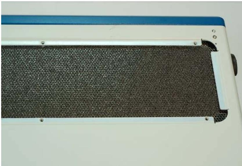
![Close-up of a white electronic device with black textured surface and blue top panel (no visible text or symbols)](.pxis-2719-50-17029-1000-007/910840a7409d93e397d346614dc4d3787e077200086a7d2e35b331bd188795e0.jpg)

6. Replace the old filter with a new one.
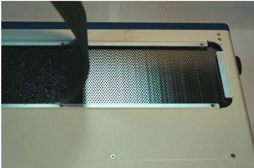
![Close-up of a white electronic device with a perforated metal grille and black handle (no visible text or symbols)](.pxis-2719-50-17029-1000-007/5db491eb4270c470fc32a463236bd6f76573c9ee8ff6610ab2fe9b1365ad401b.jpg)

7. Replace the metal plate and fasten the screws and foot stand.

# Handling the Chassis

The PXIS-2719 is designed for both rack-mounting and bench-top usage. When you transport or carry the chassis, it is recommended that you use the handle. The handle is designed to carry the weight of the chassis for superior portability and balance.

The PXIS-2719 weights 13.4 kg. Please be carefully when moving the chassis to avoid any possible injury.

# Cleaning the Exterior

Make sure that you turn the system off before cleaning the chassis exterior. Wipe the exterior with a clean cloth starting from areas that easily accumulate dust or dirt such as the area in and around the chassis and power supply air inlet apertures.

# Power Requirements

Make sure that the power cord is in good condition before plugging it into the system. You also need to check the reliability of the power source. The PXIS-2719 power supply is capable of handling 90 V to 264 V AC within the 47 Hz to 63 Hz range. Do not connect the PXIS-2719 on an already overloaded circuit.

# Important Safety Instructions

Read and follow all instructions marked on the product and in the documentation before operating the system. Retain all safety and operating instructions for future use.

▶ Read these safety instructions carefully.
- Keep this user’s manual for future reference.
The equipment should be operated in an ambient temperature between $0^{\circ}$ C to $50^{\circ}$ C.
The equipment should be operated only from the type of power source indicated on the rating label. Make sure the voltage of the power source is correct when connecting the equipment to the power outlet.
If the user's equipment has a voltage selector switch, make sure that the switch is set to the proper position for the area. The voltage selector switch is set at the factory to the correct voltage.
▶ For pluggable equipment, ensure they are installed near a socket-outlet that is easily accessible.
- Secure the power cord to prevent unnecessary accidents. Do not place anything over the power cord.
▶ If the equipment will not be in use for long periods of time, disconnect the equipment from the power outlet to avoid being damaged by transient over voltage.
▶ All cautions and warnings on the equipment must be noted.
▶ Keep this equipment away from humidity.
▶ Do not use this equipment near water or a heat source.
▶ Place this equipment on a stable surface when installing to prevent injury.
▶ Never pour any liquid into the product to prevent fire or electrical shock.

▶ Openings in the chassis are provided for ventilation. Do not block or cover these openings. Make sure there is adequate space around the system for ventilation when setting up the work area. Never insert objects of any kind into the ventilation holes.
▶ To avoid electrical shock, always unplug all power and modem cables from wall outlets before removing the system covers.
▶ The equipment must be serviced by authorized technicians when:

The power cord or plug is damaged.
▷ Liquid has penetrated the equipment.
▷ It has been exposed to moisture.
$\triangleright$ It is not functioning or does not function according to the user's manual.
▷ It has been dropped and damaged.
▷ It has an obvious sign of breakage.

▶ Never attempt to fix the equipment. For safety reasons, the equipment should only be serviced by qualified personnel.
[🔗 Link to the original document](.pxis-2719-50-17029-1000-007/pxis-2719-50-17029-1000-007.pdf)
