# RQX-59x Series

ROScube-X High-Performance AI Embedded Computer for Intelligent Robotic Development

RQX-59G/590, RQX-59G-E/590-E

User’s Manual

![Exterior view of a black RoSCube network device with ports, connectors, and ventilation controls (no readable text or symbols beyond branding)](.rqx-59x-50m-45r03-1010-11/fad0c581a7d7c78fd0b13ef649fccb5e1a76dfeefd73d7b5fbb6a25641c2263e.jpg)

Manual Rev.: 1.1

Revision Date: March 12, 2026

Part No: 50M-45R03-1010

Revision History

<table><tr><td>Revision</td><td>Release Date</td><td>Description of Change(s)</td></tr><tr><td>1.0</td><td>2024-05-06</td><td>Initial release</td></tr><tr><td>1.1</td><td>2026-03-12</td><td>Specifications updated</td></tr></table>

# Preface

# Copyright © 2024 ADLINK Technology Inc.

This document contains proprietary information protected by copyright. All rights are reserved. No part of this manual may be reproduced by any mechanical, electronic, or other means in any form without prior written permission of the manufacturer.

# Disclaimer

The information in this document is subject to change without prior notice in order to improve reliability, design, and function and does not represent a commitment on the part of the manufacturer.

In no event will the manufacturer be liable for direct, indirect, special, incidental, or consequential damages arising out of the use orinability to use the product or documentation, even if advised of the possibility of such damages.

# Environmental Responsibility

ADLINK is committed to fulfill its social responsibility to global environmental preservation through compliance with the European Union's Restriction of Hazardous Substances (RoHS) directive and Waste Electrical and Electronic Equipment (WEEE) directive. Environmental protection is a top priority for ADLINK. We have enforced measures to ensure that our products, manufacturing processes, components, and raw

![Symbol of a trash bin crossed with a diagonal line and a horizontal bar below (no text or labels)](.rqx-59x-50m-45r03-1010-11/b944ba64bb7d3b91cf551754f5e676cee5eeff659625dc2d5a7b1f0c15825b4b.jpg)

materials have as little impact on the environment as possible. When products are at their end of life, our customers are encour aged to dispose of them in accordance with the product disposal and/or recovery programs prescribed by their nation or company.

Battery Labels (for products with battery)
![Symbol of a trash bin crossed out by two diagonal lines (no text or numbers present)](.rqx-59x-50m-45r03-1010-11/a6431ce9d234d1d24d58456357356f96b69a63e3129aee386938bd9299b15533.jpg)

![Recycling symbol icon with three chasing arrows inside a square frame (no text or labels)](.rqx-59x-50m-45r03-1010-11/635b1bb841416e3d3ce0c45176a07f3a1ce246c25191704862047d1474ad7429.jpg)

Li-ion

![RECYCLE\nRBRC\nLi-ion\n1.800.822.8837](.rqx-59x-50m-45r03-1010-11/44e705bc2b5b96c61fbea6746a8f0989ecb41ad05c7abbd18d7c727227c97284.jpg)

![Abstract geometric pattern with interlocking arrows forming a cross shape (no text or symbols)](.rqx-59x-50m-45r03-1010-11/4d75876ea8c7a7f63ae34500d3abee5d5871367a8df0c84f32309e2185489880.jpg)

# California Proposition 65 Warning

![The image shows a standard caution symbol consisting of a yellow triangle with a thick black border. Centered inside the triangle is a black exclamation point.](.rqx-59x-50m-45r03-1010-11/38b446620b9b3ae4f77fb5533fb4cfe6cd25b11838ef1d7c4ffd65a6fdc2efeb.jpg)

WARNING: This product can expose you to chemicals including acrylamide, arsenic, benzene, cadmium, Tris(1,3-dichloro-2-propyl) phosphate (TDCPP), 1,4-

Dioxane, formaldehyde, lead, DEHP, styrene, DINP, BBP, PVC, and vinyl materials, which are known to the State of California to cause cancer, and acrylamide, benzene, cadmium, lead, mercury, phthalates, toluene, DEHP, DIDP, DnHP, DBP, BBP, PVC, and vinyl materials, which are known to the State of California to cause birth defects or other reproductive harm. For more information go to www.P65Warnings.ca.gov.

# Trademarks

Product names mentioned herein are used for identification purposes only and may be trademarks and/or registered trademarks of their respective companies.

# Conventions

Take note of the following conventions used throughout this manual to make sure that users perform certain tasks and instructions properly.

![The image displays an icon of a white sheet of paper with a folded upper-right corner. Faint grey horizontal lines run across the paper, indicating text. A large, red checkmark is superimposed over the center of the document.](.rqx-59x-50m-45r03-1010-11/f544d492005163a266966b6dcd4615d998c2a17453e1d6a5ee30a6e5fd6a638e.jpg)
NOTENOTE:

Additional information, aids, and tips that help users perform tasks.

![The image shows a yellow triangular warning sign with a thick black border. Centered within the triangle is a black exclamation point. The sign is set against a white background, with a thin black horizontal line visible along the very top edge.](.rqx-59x-50m-45r03-1010-11/bc8efbd5fe93c42e02679163321056ec3a5667f8a526684bea679f716ca23a0f.jpg)
CAUTION:

Information to prevent minor physical injury, component damage, data loss, and/or program corruption when trying to complete a task.

ATTENTION: Informations destinées à prévenir les blessures corporelles mineures, les dommages aux composants, la perte de données et/ou la corruption de programme lors de l'exécution d'une tâche.

![The image features a red equilateral triangle containing a white exclamation mark centered inside it.](.rqx-59x-50m-45r03-1010-11/052ccd13c9a1918edf73a396e1e27eb88df825c4b9670591eb2c77bbf5c7d5ce.jpg)
WARNING:

Information to prevent serious physical injury, component damage, data loss, and/or program corruption when trying to complete a specific task.

AVERTISSEMENT: Informations destinées à prévenir les blessures corporelles graves, les dommages aux composants, la perte de données et/ou la corruption de programme lors de l'exécution d'une tâche spécifique.

# Table of Contents

# Revision History ......

# Preface .......

# Table of Contents......

# List of Tables........

# List of Figures...... ... 10

# 1 Introduction ....... ... 12

1.1 Overview ...... .... 12

1.2 Features .... .. 12

1.3 Packing List .....

1.4 Optional Accessories ......

# 2 Specifications ........

2.1 RQX-59G(-E), RQX-59F(-E), RQX-590(-E)........

2.2 RQX-59x Series Functional Block Diagram ...........

2.3 Display Options .......

2.4 Mechanical Dimensions ....... 8

# 3 System Layout ......... .... 21

3.1 Front Panel ..... ... 21

3.1.1 Power Button.... ..23

3.1.2 Reset Button.. ..23

# RQX-59x Series

3.1.3 LED Indicators .... .. 23
3.1.4 External Power Switch . ..23
3.1.5 Multi-I/O DB-50 Connector ... .. 24
3.1.6 HDMI Connector... .. 25
3.1.7 USB 3.0 Ports.. ..25
3.1.8 Gigabit Ethernet Ports .... ..26
3.1.9 DC Power Input .. ..27
3.1.10COM Port Connectors .. .. 29
3.1.11microSD Card Slot.. ..30
3.1.12USB 2.0 OTG Port.. ..30
3.1.13mini FAKRA Connector .. ..31
3.1.14 Audio port ... .. 33

# 3.2 Internal I/O Connectors ...... ... 34

3.2.1 Board Layout ... ..34
3.2.2 Mainboard Connectors .. ... 35
3.2.3 IO Board Connectors.. ..36
3.2.4 M.2 B key Slot .. ..37
3.2.5 SIM Card Slot ... ..37
3.2.6 M.2 M Key Slot .. ..37
3.2.7 M.2 E Key Slot.. ..37
3.2.8 SW Debug Port.. ..37
3.2.9 Local/Extension Power On/Off Jumper .... ..38
3.2.10FPGA JTAG Direction from Jetson AGX Xavier GPIO or Pin Header CN1501 . .38

# 4 Getting Started........ ... 39

# 4.1 Attach DC Power Connector....... ... 39

# 4.2 Mounting the RQX-59x Series....... .... 40

4.2.1 Install the Wall-mount Brackets . ..40
4.2.2 Mounting the Device / Montage de l'Appareil .. ..41

# 4.3 Camera application in RQX-59x Series .......... ..... 42

4.3.1 Camera supporting list in RQX-59 series.. ..42

4.4 RQX-59 series flashing BSP MFI file SOP....................... 43
4.5 Expansion box application in RQX-59 series ................. 45

Appendix A Power ...... .. 51

A.1 Power Consumption Reference...... .. 51

Important Safety Instructions ......... ... 53

Consignes de Sécurité Importante....... .. 55

Getting Service ......... ..... 59

This page intentionally left blank.

# List of Tables

Table 2-1: RQX-59G/59G-E, RQX-590/590-E Specifications ...... 3
Table 2-2: Maximum Display Resolution...
Table 3-1: Front Panel I/O Legend. . 17
Table 3-2: Side Panel I/O Legend .. .. 18
Table 3-3: Multi-I/O DB-50 Connector Pin Definition ............. ... 20
Table 3-4: HDMI Connector Pin Definition .. .. 21
Table 3-5: Ethernet Port Pin Definition... .. 22
Table 3-6: Active/Link LED Indicators .... .. 23
Table 3-7: Speed LED Indicators ... .. 23
Table 3-8: DC Power Input Pin Definition.. .. 23
Table 3-9: COM Port D-Sub 9-pin RS-232/485 Pin Definitions . 25
Table 3-10: microSD Card Slot Pin Definition .. .. 26
Table 3-11: USB 2.0 OTG Micro-A/B Pin Definition.. .. 26
Table 3-12: mini FAKRA Connector Pin Definition.... . 27
Table 3-13: RQX-59x Mainboard Connector Legend.. .. 29
Table 3-14: Function Module Connector Legend.. .. 30
Table 3-15: USB 2.0 OTG Micro-A/B Pin Definition..... .. 31
Table A-1: Power Consumption.. ... 37

This page intentionally left blank.

# List of Figures

Figure 2-1: RQX-59x Series Functional Block Diagram .. .. 6

Figure 2-2: RQX-59x Series Top View .. . 8

Figure 2-3: RQX-59x(-E) Series Top View . . 9

Figure 2-4: RQX-590 Front and Rear View .. . 10

Figure 2-5: RQX-59G Front and Rear View .. . 11

Figure 2-6: RQX-59F Front and Rear View.... .. 12

Figure 2-7: RQX-590-E Front and Rear View... . 13

Figure 2-8: RQX-59G-E Front and Rear View... .. 14

Figure 2-9: RQX-59F-E Front and Rear View . . 15

Figure 2-10: RQX-59x Series Side View .. . 16

Figure 2-11: RQX-59x(-E) Series Side View ... .. 17

Figure 2-12: RQX-59x Series Bottom View... .. 18

Figure 2-13: RQX-59x(-E) Series Bottom View.. . 19

Figure 3-1: Front Panel I/O .. .. 21

Figure 3-2: Front Panel I/O .. ... 22

Figure 3-3: Ethernet Port and LEDs . . 27

Figure 3-4: DC Power Input.. .. 28

Figure 3-5: COM Port D-Sub 9-pin .... ... 30

Figure 3-6: microSD Card Slot .. .. 31

Figure 3-7: USB 2.0 OTG Micro-A/B Port.. .. 31

Figure 3-8: 1-to-4 mini FAKRA Connector. . . 32

Figure 3-9: 1-to-1 mini FAKRA Connector. . . 33

Figure 3-10: Audio Port Pin. .. .. 34

Figure 3-11: RQX-59x Board Layout . .. 35

Figure 3-12: RQX-59x Mainboard Connectors... .. 36

Figure 3-13: Function Module Connectors .. .. 37

Figure 3-14: Software Debug Port.. .. 38

This page intentionally left blank.

# 1 Introduction

# 1.1 Overview

ADLINK’s ROScube-X RQX-59x Series, a ROS 2-enabled robotic controller powered by NVIDIA® Jetson AGX Orin™, features an integrated NVIDIA Volta™ GPU, dual deep learning accelerators, along with a wide variety of interfaces including GMSL2 camera connectors for advanced robotic system integration. The RQX-59x Series support the full complement of resources developed with NVIDIA JetPack SDK and ADLINK’s Neuron SDK, and is specifically suited for robotic applications demanding highperformance AI computing capabilities with minimal power consumption.

# 1.2 Features

▶ High-performance AI embedded computer for intelligent robotic development
▶ Excellent performance per watt with power consumption as low as 40 W
▶ Ruggedized, secure connectivity with locking USB ports
▶ Comprehensive I/O for connecting a wide range of devices
▶ Time synchronization with GMSL2 camera

# 1.3 Packing List

Before unpacking, check the shipping carton for any damage. If the shipping carton and/or contents are damaged, inform your dealer immediately. Retain the shipping carton and packing materials for inspection. Obtain authorization from your dealer before returning any product to ADLINK. Upon unpacking, make sure that the following items are included in the package.

▶ RQX-59x Series Fanless Embedded Computer
▶ Accessories

▷ Power cable (lockable Molex connector to Phoenix terminal block connector)
▷ Wall-mount brackets
▷ Screw pack
▷ Power on/off extension cable

# 1.4 Optional Accessories

▶ AC/DC Adapter

▷ 160W (P/N: 31-62120-0020)
▷ 220W (P/N: 31-62149-0000)

▶ Wi-Fi Module: Wi-Fi 6 (11a/b/g/n/ac/ax 2Tx2R) + BT (V5.2), LITEON\_ENL-R8852BE (RTL8852BE) (P/N: 29-E8852-A000)

▶ LTE Module: THALES(GEMALTO), MV31-W\_L30960-N6910- B100 (P/N: 29-D3096-K030)

# 2 Specifications

2.1 RQX-59G(-E), RQX-59F(-E), RQX-590(-E)

<table><tr><td>Model Name</td><td>RQX-59G/59G-E</td><td>RQX-590/590-E</td></tr><tr><td colspan="3">System Core</td></tr><tr><td>NVIDIA Module</td><td colspan="2">NVIDIA® Jetson AGX OrinTM</td></tr><tr><td>CPU</td><td colspan="2">8-core Arm® Cortex®-A78AE v8.2 64-bit CPU2MB L2 + 4MB L3Maximum Operating Frequency: 2.2GHz</td></tr><tr><td>GPU</td><td colspan="2">NVIDIA Ampere architecture with 1792NVIDIA CUDA® cores and 56 tensorcores. 200 TOPS (INT8)Maximum Operating Frequency: 930 MHz</td></tr><tr><td>Memory</td><td colspan="2">32GB 256-bit LPDDR5. 204.8GB/s</td></tr><tr><td>eMMC</td><td colspan="2">64GB eMMC 5.1</td></tr><tr><td colspan="3">Front Panel I/O Interfaces</td></tr><tr><td>Display</td><td colspan="2">1x HDMI 2.0a</td></tr><tr><td>Ethernet</td><td colspan="2">2x GbE (IEEE 802.1AS, IEEE 1588 v2)</td></tr><tr><td>USB 3.0</td><td colspan="2">4x USB Type A2x USB Type A with lockable connector</td></tr><tr><td>Serial Port</td><td colspan="2">COM1: RS-232/485; COM2: RS-232</td></tr><tr><td>USB OTG</td><td colspan="2">1x USB 2.0 OTG Micro-A/B port for updating OS</td></tr><tr><td>microSD card slot</td><td colspan="2">1x microSD card</td></tr><tr><td colspan="3">Side Panel I/O Interfaces</td></tr><tr><td>DB-50 Connector</td><td colspan="2">UART, SPI, CAN, I2C, PWM, 20-bit GPIO</td></tr><tr><td colspan="3">Internal I/O Connectors</td></tr><tr><td>M.2 Expansion</td><td colspan="2">1x Key M 2280/3042 for Storage (NVMe SSD)1x Key E 1630/2230 for Wi-Fi1x Key B 3042/3052 socket for 5G LTE module</td></tr><tr><td>USIM</td><td colspan="2">1x USIM socket</td></tr><tr><td>RTC Battery</td><td colspan="2">CR2450W Li 3.0V 550mAh</td></tr></table>

Table 2-1: RQX-59G/59G-E, RQX-59F/59F-E, RQX-590/590-E Specifications

<table><tr><td>Model Name</td><td>RQX-59G/59C</td><td>RQX-590/590-E</td></tr><tr><td colspan="3">LED Indicators</td></tr><tr><td>User Defined</td><td colspan="2">6x user defined LEDsGreen: U1,U2,U3, U6Amber: U5Yellow: U4</td></tr><tr><td colspan="3">Camera Interfaces</td></tr><tr><td>FAKRA connectors</td><td>2x mini FAKRA quad-port connectors.(for GMSL2 camera, driver supports Automotive HDR camera C1/C2, LI-AR0233-GMSL2 (non-ISP), oToCAM264ISP, GMSL2 cameras ZED-X/ZED-X n</td><td>N/A</td></tr><tr><td colspan="3">Expansion Box (“E” models only)</td></tr><tr><td>Dimensions</td><td colspan="2">132(W) x 210(D) x 80(H) mm</td></tr><tr><td>PCIe slot</td><td colspan="2">1x PCIe Gen4 x16 slot, 1x PCIe Gen3 x4</td></tr><tr><td colspan="3">Power Requirements</td></tr><tr><td>DC Power Input</td><td colspan="2">9-36V (±5% tolerance, reverse polarity protection)</td></tr><tr><td>AC/DC Power Adapter</td><td colspan="2">160W/220W, 90-264V AC to 24 V DC power cable: lockable Molex connector to Phoenix terminal block connector</td></tr><tr><td>Power Switch</td><td colspan="2">1x power button (supports auto power-on)1x power on/off extension cable for robotics</td></tr><tr><td>Recovery and Reset</td><td colspan="2">1x recovery button1x hardware reset button</td></tr><tr><td colspan="3">Mechanical</td></tr><tr><td>Dimensions</td><td colspan="2">190(W) x 210(D) x 80(H) mm“-E” models: 322(W) x 210(D) x 80(H) mm</td></tr><tr><td>Weight</td><td colspan="2">Without expansion box: 3.4 kgWith expansion box: 4.5 kg</td></tr><tr><td>Mounting</td><td colspan="2">Wall mount kit</td></tr></table>

Table 2-1: RQX-59G/59G-E, RQX-59F/59F-E, RQX-590/590-E Specifications

<table><tr><td>Model Name</td><td>RQX-59G/59C</td><td>RQX-590/590-E</td></tr><tr><td colspan="3">Environmental</td></tr><tr><td>Operating Temperature</td><td colspan="2">-20 °C to 65 °C with 0.6 m/s airflow at 30 W (without Wi-Fi module and 5G module)</td></tr><tr><td>Operating Humidity</td><td colspan="2">Approx. 95% @40°C (non-condensing)</td></tr><tr><td>Storage Temperature</td><td colspan="2">-40°C to 85°C</td></tr><tr><td>Vibration</td><td colspan="2">IEC 60068-2-64: Operating 1Grms, 5-500 Hz, 3 axes</td></tr><tr><td>Shock</td><td colspan="2">MIL-STD-202G Method 213B, Table 213-I condition A Operating: 30G, half sine 11ms duration. (w/o expansion)</td></tr><tr><td>EMI</td><td colspan="2">CE &amp; FCC class A (EN61000-6-4/-6-2)</td></tr><tr><td>EMS</td><td colspan="2">IEC 61000-4-2 (ESD, contact: ±4kV, air: ±8kV w/ expansion)IEC 61000-4-3 (RS, 10V/m from 80-1000MHz, 3V/m from 1400-2000MHz, 1V/m from 2000-2700MHz, 1kHz sine wave, 80% AM)IEC 61000-4-4 (EFT, ±2kV at 5KHz on power port, ±1kV at 5KHz on signal port)IEC 61000-4-5 (Surge, ±2kV line to earth CM on power port, ±1kV line to earth CM on signal port)IEC 61000-4-6 (CS, 10Vrms with 1kHz sine wave, 80% AM from 0.15MHz-80MHz)IEC 61000-4-8 (power-frequency magnetic fields)IEC 61000-4-11 (voltage DIPs &amp; voltage interruptions)</td></tr><tr><td>Safety</td><td colspan="2">EN 62368-1 (LVD)</td></tr><tr><td colspan="3">Software</td></tr><tr><td>SDK</td><td colspan="2">NVIDIA Jetson SDK, Jetpack 5.1.2</td></tr><tr><td>Environment</td><td colspan="2">Ubuntu 20.04 L4T</td></tr><tr><td colspan="3">Operating System</td></tr><tr><td>Environment</td><td colspan="2">Ubuntu 20.04 L4T</td></tr><tr><td>Middleware</td><td colspan="2">ROS, ROS 2</td></tr></table>

Table 2-1: RQX-59G/59G-E, RQX-59F/59F-E, RQX-590/590-E Specifications

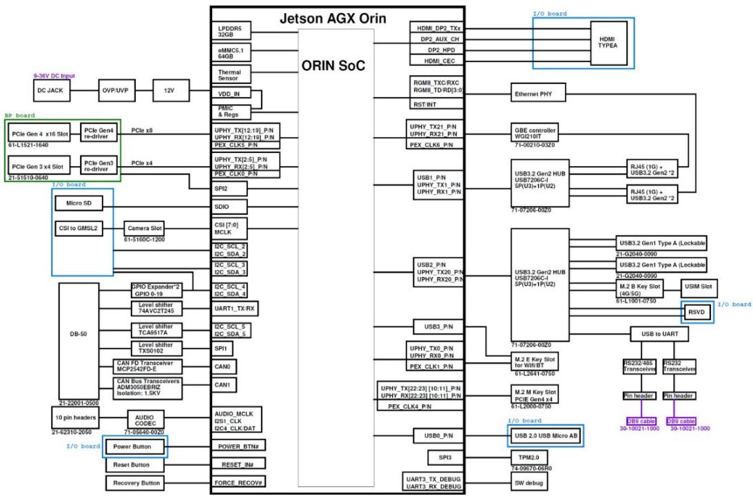
# 2.2 RQX-59x Series Functional Block Diagram
![The diagram illustrates the interconnections of the **Jetson AGX Orin** platform, specifically focusing on the **ORIN SoC** and its peripheral connections.\n\n**Central Component:**\n*   **Jetson AGX Orin**: The main block containing the **ORIN SoC**.\n\n**Left Side (BP Board Connections):**\n*   **Power & Memory:**\n    *   **DC JACK** connects to **OVP/UVP** connects to **12V** connects to **VDD_IN**.\n    *   **LPDDR5 32GB** and **eMMC5.1 64GB** connect directly to the SoC.\n    *   **Thermal Sensor** connects to **VDD_IN**.\n    *   **PMIC & FPGA** connects to the SoC.\n*   **PCIe Section (Green Box):**\n    *   **PCIe Gen 4 x16 Slot** (labeled **61-L1521-1640**) connects to **PCIe Gen4 re-driver** (connected via **PCIe x8**). This re-driver connects to **UPHY_TX(12,19)_P,N**, **UPHY_RX(12,19)_P,N**, and **PEX CLK5_P,N**.\n    *   **PCIe Gen 3 x4 Slot** (labeled **21-51519-0640**) connects to **PCIe Gen3 re-driver** (connected via **PCIe x4**). This re-driver connects to **UPHY_TX(2,5)_P,N**, **UPHY_RX(2,5)_P,N**, and **PEX CLK6_P,N**.\n*   **I/O Board (Blue Box) & DB-50:**\n    *   **Micro SD** connects to **SPI2** and **SDIO**.\n    *   **CSI to GM5L2** (labeled **61-5160C-1200**) connects to **CSI (7:0)** and **MCLK**.\n    *   **DB-50** block contains several components:\n        *   **SPIO Expander'2 GPIO 0-19** connects to **I2C_SCL_2** and **I2C_SDA_2**.\n        *   **Level shifter 74AVC2T245** connects to **I2C_SCL_3** and **I2C_SDA_3**.\n        *   **Level shifter TC49517A** connects to **UART1_TX_RX**.\n        *   **Level shifter TX50102** connects to **I2C_SCL_4** and **I2C_SDA_4**.\n        *   **CAN FD Transceiver MCP2547D-E** connects to **SPI1** and **CAN0**.\n        *   **CAN Bus Transceivers ADM3050EBRIZ Isolation: 1.5KV** connects to **CAN1**.\n*   **Buttons & Audio:**\n    *   **AUDIO_CODEC** (labeled **71-55640-0020**) connects to **AUDIO_MCLK**, **GSI_CLK**, and **I2C4_CLK, DAT**.\n    *   **Power Button** connects to **POWER_BTN#**.\n    *   **Reset Button** connects to **RESET_IN#**.\n    *   **Recovery Button** connects to **FORCE_RECOV#**.\n    *   **10 pin headers** (labeled **21-62310-2050**) and **21-22091-0500** are present in this area.\n\n**Right Side (Peripherals & I/O):**\n*   **Video & Ethernet:**\n    *   **HDMI_DP2_TXs**, **DP2_AUX_CH**, **DP2_HPD**, and **HDMI_CEC** connect to an **I/O board** block containing **HDMI TYPE A**.\n    *   **RGMI_TXC:RXC** and **RGMI_TD:RD(3:0)** connect to **RST_INT**.\n    *   **RST_INT** connects to **Ethernet PHY** connects to **GBE controller** (labeled **W5G16RT**, part number **71-00210-0320**).\n    *   **GBE controller** connects to two blocks labeled **RJ45 (1G) + USB3.2 Gen2 *2**.\n*   **USB Hubs & Ports:**\n    *   **USB1_P,N**, **UPHY_TX1_P,N**, **UPHY_RX1_P,N** connect to **USB3.2 Gen2 HUB U887206C-1 5P(U3)+1P(U2)** (part number **71-07206-0920**). This hub connects to the **RJ45** blocks mentioned above.\n    *   **USB2_P,N**, **UPHY_TX20_P,N**, **UPHY_RX20_P,N** connect to the same **USB3.2 Gen2 HUB**.\n    *   **USB3_P,N** connects to a lower **USB3.2 Gen2 HUB** block.\n    *   This lower hub connects to **USB3.2 Gen1 Type A (Lockable)** (part number **21-G2040-0090**, appearing twice), **M.2 B Key Slot** (labeled **4G 5G**, part number **61-L2641-0750**), and **USIM Slot**.\n    *   **USB0_P,N** connects to **USB 2.0 USB Micro AB** (Blue Box).\n*   **M.2 Slots:**\n    *   **UPHY_TX0_P,N**, **UPHY_RX0_P,N**, and **PEX_CLK1_P,N** connect to **M.2 E Key Slot for Wifi BT** (part number **61-L2641-0750**).\n    *   **UPHY_TX(22:23) (10,11)_P,N**, **UPHY_RX(22:23) (10,11)_P,N**, and **PEX_CLK4_P,N** connect to **M.2 M Key Slot PCIE Gen4 x4** (part number **61-L2000-0750**).\n*   **Debug & TPM:**\n    *   **SPI3** connects to **TPM2.0** (part number **74-09670-05R0**).\n    *   **UART3_TX_DEBUG** and **UART3_RX_DEBUG** connect to **SW_debug**.\n*   **Serial/UART:**\n    *   **RSVD** (Blue Box) connects to **USB to UART**.\n    *   **USB to UART** connects to **RS232-485 Transceiver** and **RS232 Transceiver**.\n    *   Both transceivers connect to **Pin header** blocks, which connect to **DB9 cable** blocks (part number **30-10021-1000**).](.rqx-59x-50m-45r03-1010-11/a5cd520a5bb65dcc07bd0afcd5b7e8a6933a1d0c1403ac6df9da2a451a15427f.jpg)

Figure 2-1: RQX-59x Series Functional Block Diagram

# 2.3 Display Options

With computing and graphic performance enhancement, the RQX-59x Series controller can support three independent displays with the following configuration.

<table><tr><td>Port</td><td>Resolution</td></tr><tr><td>HDMI 2.0a/b</td><td>4096x2160@60Hz</td></tr></table>

Table 2-2: Maximum Display Resolution

# 2.4 Mechanical Dimensions

All dimensions in mm

![210\n175\n87.50\n20.50\n5.50\n134\n186\nADLINK](.rqx-59x-50m-45r03-1010-11/e0745c2115edb25967e95b197678c57790a2f7dfce75a6aed661a43a21111533.jpg)

Figure 2-2: RQX-59x Series Top View

![208.90\n322\nADLINK](.rqx-59x-50m-45r03-1010-11/014656ffdf2bed5cc5c4f7c65cb7556097f90391660c58407378a6aac09f0363.jpg)

Figure 2-3: RQX-59x(-E) Series Top View

![88\n83.96\n80\nCOM 1\nCOM 2\nUSB\nUSB\nUSB\nUSB\nU3 U8\nU2 U5\nU1 U4\nROScube\nUSB\nPush Unlock\nUSB\nUSB\nUSB\niV - 36V DC IN\nU\nREDBM2F\nOTG\nHDMI\nETX PW SW](.rqx-59x-50m-45r03-1010-11/a5723948e2ed7f5d9b18c542108c7cbf17b67c44ecb03a0835af8fab056d75a5.jpg)

![161.50\n42 42 42 23.50 12](.rqx-59x-50m-45r03-1010-11/a8cd0e702809f1fc3d24205dccbdb6d93d1926679be379af2616a0ff7ed03803.jpg)

Figure 2-4: RQX-590 Front and Rear View

![88\n83.96\n80\nCOM 1\nCOM 2\nU3 U6\nU2 U5\nU1 U4\nUSB Push\nUnlock USB USB USB 9V - 36V DC IN RECOVERY\nOTG HDMI GMSL 2 GMSL 2 ETX PW SW\n4 1 6 5\n3 2 7 6](.rqx-59x-50m-45r03-1010-11/9566493467f0ed1577d95f3a1ca8a7ce7f4e0ef26249e1188ff179fe03334d03.jpg)

![161.50\n42 42 42 23.50 12](.rqx-59x-50m-45r03-1010-11/a87697b1935a14250872829658aa33576e6cd0e58c92d16438bd37a5ff1a97f1.jpg)

Figure 2-5: RQX-59G Front and Rear View

![88\n83.96\n80\nCOM 1\nCOM 2\nU3 U6\nU2 U5\nU1 U4\nROScube\nUSB Push Unlock USB USB USB\n9V - 36V DC IN RECOVERY\nOTG HDMI FPD-Link III FPD-Link III ETX PW SW](.rqx-59x-50m-45r03-1010-11/bf4456cc473328c51672a97bb662e1e23ac7726eaa57c45c234d4aecb9e9dc75.jpg)

![161.50\n42 42 42 23.50 12](.rqx-59x-50m-45r03-1010-11/ec70d67f16fc3abc0025deb6fbb4a23914610b5c6e16901510b455f19ae59d8b.jpg)

Figure 2-6: RQX-59F Front and Rear View

![COM 1\nCOM 2\nUSB\nPush Unlock\nUSB\nUSB\nUSB\nU1 U2 U3 U4\nU5 U6 U7 U8\nROSCube\nO10\nHDMI\nSIV - 36V DC IN\nECR P/W SW\nRECOVERY\n80](.rqx-59x-50m-45r03-1010-11/eee1978a7bada09e9624185fae447b62fbea6ddb794ffc1ad496cd5ff614a7e8.jpg)

![161.50\n42 42 42 23.50 12](.rqx-59x-50m-45r03-1010-11/0a67827445bfc910dd66bcc40f8504d969259457d81492e55f022c84bb4fcdd2.jpg)

Figure 2-7: RQX-590-E Front and Rear View

![ROScube\nCOM 1\nCOM 2\nUSB\nPush Unlock\nUSB\nUSB\nUSB\n8V - 36V DC IN\nRECOVERY\nOTG\nHDMI\nGMIL 2\nGMIL 2\n7\n8\nETX FW BW](.rqx-59x-50m-45r03-1010-11/66fe5bbb85f7cde47d9d9e9d9442d712b20c6fbc7aee46c0537f4ef5f7840477.jpg)

![161.50\n42 42 42 23.50 12](.rqx-59x-50m-45r03-1010-11/c33578cea23def4268ade52ced707d9c49f000618d80f84ac0f749504439f93c.jpg)

Figure 2-8: RQX-59G-E Front and Rear View

![COM 1\nCOM 2\nUSB\nPush\nUninot\nUSB\nFPD Link III\nFPD Link III\n4\n3\n2\n1\n0\n8\n6\n5\n4\n3\n2\n1\n0\n8\n6\n5\n4\n3\n2\n1\n0\n8\n6\n5\n4\n3\n2\n1\n0\n8\n6\n5\n4\n3\n2\n1\n0\n8\n6\n5\n4\n3\n2\n1\n0\n8\n6\n5\n4\n3\n2\n1\n0\n8\n6\n5\n4\n2\n1\n0\n8\n6\n5\n4\n3\n2\n1\n0\n8\n6\n5\n4\n3\n2\n1\n0\n8\n6\n5\n4\n3\n2\n1\n0\n8\n6\n5\n4\n3\n2\n1\n0\n8\n6\n5\n4\n3\n2\n1\n0\n8\n6\n5\n4\n3\n2\n98](.rqx-59x-50m-45r03-1010-11/1beb61801f8c3ef02aeed4d34f91d0c49b6123a4e99889b74acac04ca46f89ec.jpg)

![161.50\n42 42 42 23.50 12](.rqx-59x-50m-45r03-1010-11/be4435a83c6680d5be34f74e1b47196de76715647cabf12540ddaaeb45a1e7a7.jpg)

Figure 2-9: RQX-59F-E Front and Rear View

![Multi-U/O\nAudio INPUT\n0\n1](.rqx-59x-50m-45r03-1010-11/5b7294f92941a80a85da9c9163c750dc70e791548dd9d16554f81c6c7085c083.jpg)

![Technical line drawing of a mechanical component with no visible text or symbols](.rqx-59x-50m-45r03-1010-11/1def60aac81b0e4c40c6e822d465300a6bdcb500c1f62398915ad5154f5196f0.jpg)

Figure 2-10: RQX-59x Series Side View

![Multi-U/O\nAudio INPUT](.rqx-59x-50m-45r03-1010-11/2dec8b128c1eeef445e609bca19808d686cfbc57362abba43bbcc06dcd79636d.jpg)

![Technical line drawing of a multi-level mechanical or electrical component with mounting holes and mounting brackets (no text or symbols)](.rqx-59x-50m-45r03-1010-11/13352a3619787599ede6d9c5348a721597030ae4bd61a48c45e6c38a7427b524.jpg)

Figure 2-11: RQX-59x(-E) Series Side View

![219\n20](.rqx-59x-50m-45r03-1010-11/f9a073faa7c3f8ebb84ee1fd2448c24ef871df5a0ff7616c3e5ccd580aef9f6a.jpg)

Figure 2-12: RQX-59x Series Bottom View

![336.79\n20](.rqx-59x-50m-45r03-1010-11/783d6bcc2bffc5749ae974ee5168ed78f9cfa1e8f716790c77d6a50792264913.jpg)

Figure 2-13: RQX-59x(-E) Series Bottom View

This page intentionally left blank.

# 3 System Layout

# 3.1 Front Panel

The RQX-59x Series provides the following front panel access features.

![A\nB\nC\nD\nE\nF\nG\nH\nCOM 1\nCOM 2\nU3 U8\nU2 U5\nU1 U4\n9V - 38V DC IN\nROScube\nPush Unlock\n20≤10\n20≤10\n20≤10\nOTG\nHDMI\nGMSL 2\n4 1\n3 2\nGMSL 2\n8 5\n7 6\nETX\nPW SW\nRECOVERY\nO I J K L M N](.rqx-59x-50m-45r03-1010-11/21540f71b34b780e3b2ca86fd09b95e61c02374fc9ec4b3a5b6e675f7d4ccabd.jpg)

Figure 3-1: Front Panel I/O

<table><tr><td>A</td><td>Lockable USB 3.0 Type A x2</td><td>I</td><td>USB 2.0 OTG port x1</td></tr><tr><td>B</td><td>COM Port x2</td><td>J</td><td>HDMI port with screw x1</td></tr><tr><td>C</td><td>USB 3.0 Type A x4</td><td>K</td><td>Mini FAKRA quad connector x2 (only on RQX-59G/-E, RQX-59F/-E)</td></tr><tr><td>D</td><td>Gigabit Ethernet x2</td><td>L</td><td>Power ON/OFF button</td></tr><tr><td>E</td><td>User define LEDs x6</td><td>M</td><td>Power on/off extension connector</td></tr><tr><td>F</td><td>ATX DC power input</td><td>N</td><td>microSD card slot x1</td></tr><tr><td>G</td><td>Reset button</td><td>O</td><td>Ground screw</td></tr><tr><td>H</td><td>Recovery button</td><td></td><td></td></tr></table>

Table 3-1: Front Panel I/O Legend

The RQX-59x Series provides the following side panel access features.

![A\nB\nMR18-UO\nAudio INPUT](.rqx-59x-50m-45r03-1010-11/7ff23280e2326f280b36aa45adc2e50eb72a2d1883ae9028463cfcea1ff78c77.jpg)

Figure 3-2: Front Panel I/O

<table><tr><td>A</td><td>Multi-I/O (DB-50)</td></tr><tr><td>B</td><td>Audio In/out</td></tr></table>

Table 3-2: Side Panel I/O Legend

# 3.1.1 Power Button

The power button is a non-latched push button with a blue LED indicator. The system is turned on when the button is pressed, and the power LED lights. If the system hangs, press and hold the button for 5 seconds to turn it off.

# 3.1.2 Reset Button

The reset button executes a hard system reset.

# 3.1.3 LED Indicators

Six user-defined LEDs are provided on the front panel.

<table><tr><td>LED</td><td>Color</td><td>LED</td><td>Color</td></tr><tr><td>U3</td><td>Green</td><td>U6</td><td>Green</td></tr><tr><td>U2</td><td>Green</td><td>U5</td><td>Amber</td></tr><tr><td>U1</td><td>Green</td><td>U4</td><td>Yellow</td></tr></table>

# 3.1.4 External Power Switch

The External power switch allows user to use extended power on/off cable to control system power on and off.

![1\n2\n3\n4](.rqx-59x-50m-45r03-1010-11/3346ba9fa56ddee3aadbfe9988cb480d52503a0220f9130bc3f59f6f10c37c48.jpg)

<table><tr><td>Pin #</td><td>Signal</td><td>Pin #</td><td>Signal</td></tr><tr><td>1</td><td>GND</td><td>2</td><td>LED -</td></tr><tr><td>3</td><td>POWER BTN</td><td>4</td><td>LED +</td></tr></table>

# 3.1.5 Multi-I/O DB-50 Connector

The RQX-59x Series provides comprehensive I/O for autonomous robotics via a DB-50 connector on the right side of the chassis: GPIO/UART/CAN BUS/SPI/I2C signals. PWM frequency range is from 25 kHz to 2 Hz.

![17\n50\n1\n34](.rqx-59x-50m-45r03-1010-11/e92c3a4285949eb7ac38e5f28aa5f05bdb716c38ef38d905407b6aa2f15c9ca6.jpg)

<table><tr><td>Pin</td><td>Signal</td><td>Level</td><td>Pin</td><td>Signal</td><td>Level</td></tr><tr><td>1</td><td>CAN1_H</td><td>5V</td><td>26</td><td>SPI_MOSI</td><td>3.3V</td></tr><tr><td>2</td><td>CAN1_L</td><td>5V</td><td>27</td><td>GPIO 13</td><td>3.3V</td></tr><tr><td>3</td><td>GPS_UART_TX_CN</td><td>3.3V</td><td>28</td><td>GPIO 14</td><td>3.3V</td></tr><tr><td>4</td><td>GPS_UART_RX_CN</td><td>3.3V</td><td>29</td><td>GPIO 15</td><td>3.3V</td></tr><tr><td>5</td><td>GPIO 0</td><td>3.3V</td><td>30</td><td>GPIO 16</td><td>3.3V</td></tr><tr><td>6</td><td>GPIO 1</td><td>3.3V</td><td>31</td><td>GPIO 17</td><td>3.3V</td></tr><tr><td>7</td><td>GPIO 2</td><td>3.3V</td><td>32</td><td>GPIO 18</td><td>3.3V</td></tr><tr><td>8</td><td>GPIO 3</td><td>3.3V</td><td>33</td><td>GPIO 19</td><td>3.3V</td></tr><tr><td>9</td><td>GPIO 4</td><td>3.3V</td><td>34</td><td>CAN1_ISOGND</td><td></td></tr><tr><td>10</td><td>GPIO 5</td><td>3.3V</td><td>35</td><td>Encoder2_IN</td><td>3.3V</td></tr><tr><td>11</td><td>GPIO 6</td><td>3.3V</td><td>36</td><td>LIDAR_TX_CN</td><td>3.3V</td></tr><tr><td>12</td><td>GPIO 7</td><td>3.3V</td><td>37</td><td>Encoder1_IN_CN</td><td>3.3V</td></tr><tr><td>13</td><td>GPIO 8</td><td>3.3V</td><td>38</td><td>UART_RX</td><td>3.3V</td></tr><tr><td>14</td><td>GPIO 9</td><td>3.3V</td><td>39</td><td>UART_TX</td><td>3.3V</td></tr><tr><td>15</td><td>GPIO 10</td><td>3.3V</td><td>40</td><td>CAN0_H</td><td>3.3V</td></tr><tr><td>16</td><td>GPIO 11</td><td>3.3V</td><td>41</td><td>CAN0_L</td><td>3.3V</td></tr><tr><td>17</td><td>GPIO 12</td><td>3.3V</td><td>42</td><td>I2C_CLK</td><td>3.3V</td></tr><tr><td>18</td><td>CAN1_ISOGND</td><td></td><td>43</td><td>I2C_DATA</td><td>3.3V</td></tr><tr><td>19</td><td>NC</td><td></td><td>44</td><td>5V</td><td rowspan="2">max. current: 1A</td></tr><tr><td>20</td><td>PPS_OUT_CN</td><td>3.3V</td><td>45</td><td>5V</td></tr><tr><td>21</td><td>PPS_IN</td><td>3.3V</td><td>46</td><td>3.3V</td><td>max. current: 1A</td></tr><tr><td>22</td><td>PWM</td><td>3.3V</td><td>47</td><td>GND</td><td></td></tr><tr><td>23</td><td>SPI_CLK</td><td>3.3V</td><td>48</td><td>GND</td><td></td></tr><tr><td>24</td><td>SPI_CS</td><td>3.3V</td><td>49</td><td>GND</td><td></td></tr><tr><td>25</td><td>SPI_MISO</td><td>3.3V</td><td>50</td><td>GND</td><td></td></tr></table>

Table 3-3: Multi-I/O DB-50 Connector Pin Definition

# 3.1.6 HDMI Connector

The RQX-59x Series provides one HDMI connector with lock screw for connection to an external monitor.

![19 17\n3 1\n18\n4 2](.rqx-59x-50m-45r03-1010-11/dfa14f8c12f7066003b76beb1e075058242951e78e74294ed04018a4465d4469.jpg)

<table><tr><td>Pin #</td><td>Signal</td><td>Pin #</td><td>Signal</td></tr><tr><td>1</td><td>TMDS Data2+</td><td>2</td><td>TMDS Data2 Shield</td></tr><tr><td>3</td><td>TMDS Data2-</td><td>4</td><td>TMDS Data1+</td></tr><tr><td>5</td><td>TMDS Data1 Shield</td><td>6</td><td>TMDS Data1-</td></tr><tr><td>7</td><td>TMDS Data0+</td><td>8</td><td>TMDS Data0 Shield</td></tr><tr><td>9</td><td>TMDS Data0-</td><td>10</td><td>TMDS Clock+</td></tr><tr><td>11</td><td>TMDS Clock Shield</td><td>12</td><td>TMDS Clock-</td></tr><tr><td>13</td><td>CEC</td><td>14</td><td>Reserved</td></tr><tr><td>15</td><td>SCL</td><td>16</td><td>SDA</td></tr><tr><td>17</td><td>DDC/CEC Ground</td><td>18</td><td>+5 V Power</td></tr><tr><td>19</td><td>Hot Plug Detect</td><td></td><td></td></tr></table>

Table 3-4: HDMI Connector Pin Definition

# 3.1.7 USB 3.0 Ports

The RQX-59x Series provides 2x USB 3.0 Type A lockable ports and 4x USB 3.0 Type A standard ports on the front panel. All USB 3.0 ports are compatible with SuperSpeed Gen1, high-speed, full speed, and low-speed USB device.

<table><tr><td>USB 3.0 Ports</td><td>Lockable USB 3.0 Ports</td></tr><tr><td>Speed: 5G/bpsColor: BlueVoltage: 5VCurrent: 1A continueInrush current: 1.3A maxProtection: OVP, OCP</td><td>Speed: 5G/bpsColor: BlueVoltage: 5VCurrent: 1.8A continueInrush current: 2A maxProtection: OVP, OCP</td></tr></table>

# 3.1.8 Gigabit Ethernet Ports

There are two Gigabit Ethernet ports on the front panel supporting the following:

▶ IEEE 802.3az Energy Efficient Ethernet
▶ IEEE 802.1as-2011 Timing and Synchronization for Time-Sensitive Applications in Bridged Local Area Networks
▶ IEEE 802.31 Qav Forwarding and Queuing Enhancements for Time-Sensitive Streams
▶ IEEE 802.3x Pause Packets and Priority Flow Control
▶ Support for frames of up to 9KB

<table><tr><td>Speed LEDGreen/Orange</td><td>Active/LinkYellow</td></tr></table>

![8\n1](.rqx-59x-50m-45r03-1010-11/931ea192d8a7f52fa4a522b589f6de7246ee080ea99b17bd1345e4d07290e3f2.jpg)

Figure 3-3: Ethernet Port and LEDs

<table><tr><td>Pin #</td><td>10BASE-T/100BASE-TX</td><td>1000BASE-T</td></tr><tr><td>1</td><td>TX+</td><td>LAN_TX0+</td></tr><tr><td>2</td><td>TX-</td><td>LAN_TX0-</td></tr><tr><td>3</td><td>RX+</td><td>LAN_TX1+</td></tr><tr><td>4</td><td>—</td><td>LAN_TX2+</td></tr><tr><td>5</td><td>—</td><td>LAN_TX2-</td></tr><tr><td>6</td><td>RX-</td><td>LAN_TX1-</td></tr><tr><td>7</td><td>—</td><td>LAN_TX3+</td></tr><tr><td>8</td><td>—</td><td>LAN_TX3-</td></tr></table>

Table 3-5: Ethernet Port Pin Definition

<table><tr><td>LED Color</td><td>Status</td><td>Description</td></tr><tr><td rowspan="2">Yellow</td><td>Off</td><td>Ethernet port is disconnected.</td></tr><tr><td>Blinking</td><td>Ethernet port is connected and active.</td></tr></table>

Table 3-6: Active/Link LED Indicators

<table><tr><td>LED Color</td><td>Status</td><td>Description</td></tr><tr><td rowspan="3">Green/Orange</td><td>Off</td><td>10 Mbps</td></tr><tr><td>Amber</td><td>100 Mbps</td></tr><tr><td>Green</td><td>1000 Mbps</td></tr></table>

Table 3-7: Speed LED Indicators

# 3.1.9 DC Power Input

9V- 36V DC IN

![10\n5\n6\n1](.rqx-59x-50m-45r03-1010-11/db892d838b48a5308a658412a8200be43b8825558646a44ff261dcbdb2f3fbaf.jpg)

Figure 3-4: DC Power Input

<table><tr><td>Pin</td><td>Signal</td><td></td><td></td></tr><tr><td>1</td><td>GND</td><td>6</td><td>VCC (9-36VDC)</td></tr><tr><td>2</td><td>GND</td><td>7</td><td>VCC (9-36VDC)</td></tr><tr><td>3</td><td>GND</td><td>8</td><td>VCC (9-36VDC)</td></tr><tr><td>4</td><td>GND</td><td>9</td><td>VCC (9-36VDC)</td></tr><tr><td>5</td><td>GND</td><td>10</td><td>VCC (9-36VDC)</td></tr></table>

Table 3-8: DC Power Input Pin Definition

Refer to Section 4.1: Attach DC Power Connector on page 33 to install the DC Power Connector to the DC Power Input.

Please use an approved power source certified by IEC or UL. The maximum ambient operating temperature (Tma) is described in “Important Safety Instructions”. Altitude during operation is up to 2000 m whereoutput meets LPS and SELV circuit requirements.

Power Source Rating

<table><tr><td></td><td>Voltage</td><td>Current (RQX-590/59G)</td><td>Current (RQX-590-E/59G-E)</td></tr><tr><td>DC Power Source</td><td>9 to 36V DC</td><td>17.5A to 4.4A</td><td>24.44A to 6.11A</td></tr><tr><td>AC-to-DC Adapter</td><td>24V DC</td><td>6.67A</td><td>9.17A</td></tr></table>

![The image displays a red triangular warning sign with a black border. Centered inside the triangle is a large white exclamation mark ('!'). The symbol is set against a white background, with a thin horizontal black line visible along the very top edge of the image.](.rqx-59x-50m-45r03-1010-11/6374d8e34f13dd8670d676ad591c9f6393b46a7089db31ddfd7c1b57786ce588.jpg)
WARNING:

Before providing DC power, ensure the voltage and polarity provided are compatible with the DC input. Improper input voltage and/or polarity can be responsible for system damage.

AVERTISSEMENT: Avant de fournir une alimentation CC, assurez-vous que la tension et la polarité fournies sont compatibles avec l'entrée CC. Une tension d'entrée et / ou une polarité incorrectes peuvent être responsables de dommages au système.

# 3.1.10 COM Port Connectors

The RQX-59x Series provides two COM ports through D-sub 9-pin connectors. COM1 support RS-232/485 (software configurable) and COM2 supports RS-232.

![1\n5\n6\n9](.rqx-59x-50m-45r03-1010-11/94b68834fe7389ae16a72a50d58686d0e8a180587767b5aa7d1644533963da93.jpg)

Figure 3-5: COM Port D-Sub 9-pin

<table><tr><td rowspan="2">Pin</td><td colspan="2">Signal Name</td></tr><tr><td>RS-232</td><td>RS-485</td></tr><tr><td>1</td><td>DCD#</td><td>485DATA-</td></tr><tr><td>2</td><td>RXD</td><td>485DATA+</td></tr><tr><td>3</td><td>TXD</td><td>N/S</td></tr><tr><td>4</td><td>DTR#</td><td>N/S</td></tr><tr><td>5</td><td>GND</td><td>N/S</td></tr><tr><td>6</td><td>DSR#</td><td>N/S</td></tr><tr><td>7</td><td>RTS#</td><td>N/S</td></tr><tr><td>8</td><td>CTS#</td><td>N/S</td></tr><tr><td>9</td><td>RI#</td><td>N/S</td></tr><tr><td rowspan="2">Mode</td><td>Mode0=1</td><td>Mode0=0</td></tr><tr><td>Mode1=0</td><td>Mode1=1</td></tr></table>

Table 3-9: COM Port D-Sub 9-pin RS-232/485 Pin Definitions

To change the mode for your device, open the terminal interface in Ubuntu and use the command:

/sys/class/sp339\_mode\_ctl/

echo rs232 or rs485

# 3.1.11 microSD Card Slot

The RQX-59x Series provides a micro SD card slot supporting storage up to 2 TB.

![A black and white line drawing of a SIM card, showing a rectangular shape with a cut corner in the upper left containing three small vertical rectangles representing contact pins.](.rqx-59x-50m-45r03-1010-11/c623f4a851c92a31e41decdc88380581aed8fc3d994880dc8a2a7521cc624770.jpg)

![The image is a black-and-white line drawing of a technical schematic or diagram. It depicts a large horizontal rectangular frame. Along the top edge, there is a row of approximately 12 small, identical rectangular shapes, each containing a vertical line, resembling pills or small components. Below this row, the lower section contains a mechanical assembly consisting of a vertical rectangular frame on the left, a long horizontal rectangular bar in the center, and another rectangular shape on the right. There is no text visible in the image.](.rqx-59x-50m-45r03-1010-11/e6adba1a175a8a2e104ac4123fd652c4c7bbba101b946dc3a19f05a73c620d4b.jpg)
Figure 3-6: microSD Card Slot

<table><tr><td>Pin</td><td>Signal</td><td>Pin</td><td>Signal</td></tr><tr><td>1</td><td>DATA2</td><td>7</td><td>DATA0</td></tr><tr><td>2</td><td>DATA3</td><td>8</td><td>DATA1</td></tr><tr><td>3</td><td>CMD</td><td>9</td><td>GND</td></tr><tr><td>4</td><td>VDD</td><td>10</td><td>GND</td></tr><tr><td>5</td><td>CLK</td><td>11</td><td>DET</td></tr><tr><td>6</td><td>GND</td><td>12</td><td>GND</td></tr></table>

Table 3-10: microSD Card Slot Pin Definition

# 3.1.12 USB 2.0 OTG Port

This USB 2.0 OTG port is provided for system recovery and to update the software image.

![The image features the number **12345** in black text centered at the top. Below it is a diagram of a connector housing. The housing is a gray rectangle with rounded corners. Inside the upper portion of the gray housing, there are five vertical yellow pins arranged in a row. Directly beneath the pins is a white rectangular section representing the socket. Two small white rectangular feet extend downward from the bottom edge of the gray housing.](.rqx-59x-50m-45r03-1010-11/f0322d62cce3ffed4668a252e82de9d46093a46782384aeaba84b00e7d4adcc5.jpg)
Figure 3-7: USB 2.0 OTG Micro-A/B Port

<table><tr><td>Pin</td><td>Signal</td></tr><tr><td>1</td><td>VBUS</td></tr><tr><td>2</td><td>D-</td></tr><tr><td>3</td><td>D+</td></tr><tr><td>4</td><td>ID</td></tr><tr><td>5</td><td>GND</td></tr></table>

Table 3-11: USB 2.0 OTG Micro-A/B Pin Definition

# 3.1.13 mini FAKRA Connector

The mini FAKRA connector is only available on the RQX-59G(-E)/ RQX-59F(-E) series, and provides quad ports for each connector. A total of 8 devices can be connected to RQX-59G(-E) / RQX-59F(- E). The RQX-59G/ RQX-59F(-E) provides 8 camera channels using 4 dual GMSL2 deserializers or 4 dual FPD-Link III deserializers. The detailed mappings between the camera, sensor ID, Fsync GPIO, and MIPI CSI-2 are as follows:

<table><tr><td>Camera #</td><td>Sensor ID</td><td>Fsync GPIO #</td><td>MIPI CSI-2</td></tr><tr><td>1</td><td>0</td><td rowspan="2">/sys/class/gpio/gpio440</td><td rowspan="2">CSI-0 / CSI-ACSI-1 / CSI-B</td></tr><tr><td>2</td><td>1</td></tr><tr><td>3</td><td>2</td><td rowspan="2">/sys/class/gpio/gpio397</td><td rowspan="2">CSI-2 / CSI-CCSI-3 / CSI-D</td></tr><tr><td>4</td><td>3</td></tr><tr><td>5</td><td>4</td><td rowspan="2">/sys/class/gpio/gpio487</td><td rowspan="2">CSI-4 / CSI-ECSI-5 / CSI-F</td></tr><tr><td>6</td><td>5</td></tr><tr><td>7</td><td>6</td><td rowspan="2">/sys/class/gpio/gpio486</td><td rowspan="2">CSI-6 / CSI-GCSI-7 / CSI-H</td></tr><tr><td>8</td><td>7</td></tr></table>

Table 3-12: mini FAKRA Connector Pin Definition

Quad Fakra GMSL/FPD-Link Cable: 4 position mate-AX to 4x FAKRA Z- code 50Ω cable. Cable lengths of 1, 3, 6 and 12 meters are available.

<table><tr><td>P/N</td><td>Description</td></tr><tr><td>30-60185-0000-A0</td><td>1 meter 1:4 FAKRA cable</td></tr><tr><td>30-60185-0000-A0</td><td>3 meter 1:4 FAKRA cable</td></tr><tr><td>30-60185-0000-A0</td><td>6 meter 1:4 FAKRA cable</td></tr><tr><td>30-60185-0000-A0</td><td>12 meter 1:4 FAKRA cable</td></tr></table>

![The image displays a schematic of a wiring harness assembly with the following components and connections:\n\n*   **Left Block:** A multi-pin connector block.\n*   **Central Element:** A cable extending from the left connector with a white rectangular label attached. The text on the label is: 'Take if wiring harness is not in correct position'.\n*   **Right Blocks:** Four individual connectors arranged in a vertical column.\n*   **Connections:** The main cable splits into four separate wires that branch out from the central label area. Each of the four wires connects the main assembly to one of the four individual connectors on the right.](.rqx-59x-50m-45r03-1010-11/af7e7d9079be5ff0f78ff47f4a55c2cf7efbb48df8fb06ba664fbfd79bd19ee8.jpg)

Figure 3-8: 1-to-4 mini FAKRA Connector

Fakra-Plug-to-Jack Cable: 1 position mate-AX to 1x FAKRA Zcode 50Ω cable. Cable lengths of 1, 3, 6 and 12 meters are available. All cables below are of IP69K ratings.

<table><tr><td>P/N</td><td>Description</td></tr><tr><td>30-60218-0000-A0</td><td>1 meter FAKRA Plug to FAKRA Jack cable</td></tr><tr><td>30-60218-1000-A0</td><td>3 meter FAKRA Plug to FAKRA Jack cable</td></tr><tr><td>30-60218-2000-A0</td><td>6 meter FAKRA Plug to FAKRA Jack cable</td></tr><tr><td>30-60218-3000-A0</td><td>9 meter FAKRA Plug to FAKRA Jack cable</td></tr><tr><td>30-60218-4000-A0</td><td>12 meter FAKRA Plug to FAKRA Jack cable</td></tr></table>

![Technical line drawing of a mechanical component with cylindrical shaft and mounting bracket (no text or symbols)](.rqx-59x-50m-45r03-1010-11/02c7fe34865af35381d400113ea639fd467c5aa80ac10c1196fe7895d6419789.jpg)

Figure 3-9: 1-to-1 mini FAKRA Connector

# 3.1.14 Audio port

RQX-59G(-E)/ RQX-59F(-E)/ RQX-590(-E) series provides audio signals for microphone, headphone and speaker. Users must beware not to plug in the wrong pin direction, otherwise it will cause the audio IC chip to break down. This audio port does not support hot plug. The detailed pin definition of audio in/out port is as follows:

![The image displays a red triangle with rounded corners containing a centered white exclamation mark.](.rqx-59x-50m-45r03-1010-11/dfbdba7dcfac8b8c0a5f0fab0aa358da0b9c868b142a693099c89494d5f5a276.jpg)
WARNING:

Do not plug in or unplug the audio when the system is powered, otherwise damages could be done to the system.

![Audio INPUT\n9\n10\n1\n2](.rqx-59x-50m-45r03-1010-11/fc3c4754e30af188e6f0e65fc71a28039061e5fba76e84fba11c2699d0648598.jpg)

Figure 3-10: Audio Port Pin

<table><tr><td>Pin</td><td>Signal</td><td>Pin</td><td>Signal</td></tr><tr><td>1</td><td>MIC_CN_L</td><td>2</td><td>SPKR_L_P_CN</td></tr><tr><td>3</td><td>MIC_CN_R</td><td>4</td><td>SPKR_L_N_CN</td></tr><tr><td>5</td><td>HP_CN_L</td><td>6</td><td>SPKR_R_P_CN</td></tr><tr><td>7</td><td>HP_CN_R</td><td>8</td><td>SPKR_R_N_CN</td></tr><tr><td>9</td><td>MIC_IN_DET</td><td>10</td><td>GND</td></tr></table>

Table 3-13: audio port Pin Definition

# 3.2 Internal I/O Connectors

# 3.2.1 Board Layout

![Main Board\nIO Board](.rqx-59x-50m-45r03-1010-11/c67098bcea504280a16a5b6f4ac461dc25ab63e9e8abc22e6153e445c9e7a0c3.jpg)

Figure 3-11: RQX-59x Board Layout

# 3.2.2 Mainboard Connectors

![A\nB\nC\nD\nE\nF\nG\nH\nB](.rqx-59x-50m-45r03-1010-11/19145b67149338202cc71301ac8a555aed7c3253c8a97ea76cb7f090d818bc38.jpg)

Figure 3-12: RQX-59x Mainboard Connectors

<table><tr><td>A</td><td>DB50 connector</td><td>E</td><td>M.2 B Key slot</td></tr><tr><td>B</td><td>Carrier Board B2B connector</td><td>F</td><td>SIM card slot</td></tr><tr><td>C</td><td>M.2 M Key slot</td><td>G</td><td>MIPI B2B connector</td></tr><tr><td>D</td><td>M.2 E Key slot</td><td>H</td><td>IO Board B2B connector</td></tr></table>

Table 3-13: RQX-59x Mainboard Connector Legend

# 3.2.3 IO Board Connectors

![A\nB\nC\nD\nD\nE\nF\nG](.rqx-59x-50m-45r03-1010-11/2b4b1fcebc667b995d21d02ca78ab2557b97f4e9b94edb6a7ae4883b95e3c2e1.jpg)

Figure 3-13: Function Module Connectors

<table><tr><td>A</td><td>microSD card slot</td></tr><tr><td>B</td><td>Extend power header</td></tr><tr><td>C</td><td>Power On/Off button</td></tr><tr><td>D</td><td>Mini FAKRA connector</td></tr><tr><td>E</td><td>HDMI Connector</td></tr><tr><td>F</td><td>USB 2.0 OTG Micro-A/B (for recovery)</td></tr><tr><td>G</td><td>Local/Extension Power On/Off Jumper</td></tr></table>

Table 3-14: Function Module Connector Legend

# 3.2.4 M.2 B key Slot

The M.2 B Key slot supports 3042 and 3052 sizes for 5G module (USB and USIM signals). (Connector label: CN1601).

# 3.2.5 SIM Card Slot

The SIM card socket connects to the Mini PCIe slot (CN) on the mainboard. (Connector label: CN1602)

# 3.2.6 M.2 M Key Slot

The M.2 M Key slot supports 3042 and 2280 sizes for PCIe x2 NVMe storage. (Connector label: CN2101).

# 3.2.7 M.2 E Key Slot

The M.2 E Key slot supports 1630 and 2230 sizes for Wi-Fi module (PCIe and USB2.0 signals). (Connector label: CN2001).

# 3.2.8 SW Debug Port

An internal pin header is provided for software debug (CN2301).

![The image displays a technical engineering drawing of a mechanical part with dimensions and tolerances. The text visible in the drawing is:\n\n**Top Section:**\n*   2.5±0.05\n*   2.5±0.25\n*   50\n*   60\n*   1 (enclosed in a circle)\n\n**Middle/Left Section:**\n*   3.64±0.02 5x\n*   2.5±0.15\n*   5.08±0.25\n*   7.62±0.10\n\n**Right Section:**\n*   6.08±0.25\n*   3.00±0.25](.rqx-59x-50m-45r03-1010-11/b5d75b5e46b739cb680c8a6b076af6475d1c16663d969ecedf2c0465ce6b74c8.jpg)
Figure 3-14: Software Debug Port

<table><tr><td>Pin</td><td>Signal</td></tr><tr><td>1</td><td>UART3_TX</td></tr><tr><td>2</td><td>UART3_RX</td></tr><tr><td>3</td><td>GND</td></tr></table>

Table 3-15: USB 2.0 OTG Micro-A/B Pin Definition

# 3.2.9 Local/Extension Power On/Off Jumper

This jumper switch (JP1201) puts on CN1202 pin 1 and pin 2 for local power on system. Jumper switch (JP1201) puts on CN1202 pin 2 and pin 3 for extension power on system.

![3\n2\n1](.rqx-59x-50m-45r03-1010-11/775d13cdce825778db617b0467ee7ca4b0ce92c2ee85ff5d0237daa3aef8f0ce.jpg)

CN1202

![4.00±0.1](.rqx-59x-50m-45r03-1010-11/059c0537d910554307af3079e7608371b58cfcc6376b1929ce539daf3daf9e21.jpg)

JP1201

<table><tr><td colspan="2">CN1202 Power button Selection</td></tr><tr><td>1-2</td><td>Internal/Local</td></tr><tr><td>2-3</td><td>External</td></tr></table>

Table 3-16: Power Button Jumper Selection Pin Definition

# 3.2.10 FPGA JTAG Direction from Jetson AGX Xavier GPIO or Pin Header CN1501

Default setting is 1-4 ON

<table><tr><td>Switch Number</td><td>Pin description</td></tr><tr><td>1-4 ON</td><td>Jetson AGX Xavier GPIO</td></tr><tr><td>1-4 OFF</td><td>Pin header CN1501</td></tr></table>

Table 3-17: FPGA JTAG Pin Definition

# 4 Getting Started

This chapter describes the steps needed to begin using the RQX-59x Series in your application.

# 4.1 Attach DC Power Connector

Locate the DC power cable shown below that is included in the Accessory Box. Insert connector P2 into the ATX DC Power Input “F” shown in Figure 3-1 on page 17.

![P1\n1\n2\n10 5\n6 1\nP2](.rqx-59x-50m-45r03-1010-11/572262a9243959c171351770107029f3d16c0c5349d672cf5970cb6142447ebb.jpg)

Connect a DC power source as described in Section 3.1.9: DC Power Input (on page 23) to the inputs of connector P1, connecting “positive” (red) to Pin1 and “negative” (black) to Pin 2.

![The image shows a red triangle containing a white exclamation point centered within it. Below the triangle is the word 'WARNING' in black capital letters, all set against a white background.](.rqx-59x-50m-45r03-1010-11/70c0773dfc9a4e6ad54310507d2de0e1cd8025fdb991b87b82bfe73e6bfa0835.jpg)

Before providing DC power, ensure the voltage and polarity provided are compatible with the DC input. Improper input voltage and/or polarity can be responsible for system damage.

AVERTISSEMENT: Avant de connecter à une source de courant continu, veuillez vous assurer de la polarité de la tension conformément à l'entrée CC du PC. Une tension et/ou une polarité incorrectes peuvent causer des dommages irréversibles sur le système.

# 4.2 Mounting the RQX-59x Series

# 4.2.1 Install the Wall-mount Brackets

Use the 4 M4 6mm screws included in the Accessory Box to attach the 2 included wall-mount brackets to the chassis as indicated by the red circles below.

Utilisez les 4 vis M4 6 mm incluses dans la boîte d'accessoires pour fixer les 2 supports de montage mural inclus au châssis, comme indiqué par les cercles rouges ci-dessous.

![219\n20\nwall-mount\nbrackets\nbracket](.rqx-59x-50m-45r03-1010-11/368c72f8cc01bc5a498dab4550c6c5a861705dd8fe2cc72186111cf7fc010c8f.jpg)

# 4.2.2 Mounting the Device / Montage de l'Appareil

Mount the device to a wall using the 4 keyhole openings indicated or the 6 mounting holes circled in red, according to the spacing dimensions of the holes in the bracket as shown in Figure 2-2 RQX-59x Series Top View.

Montez l'appareil sur un mur à l'aide des 4 ouvertures de trou de serrure en fonction des dimensions d'espacement des trous dans le support, comme indiqué dans Figure 2-2 RQX-59x Series Top View.

![219\n20\nkeyhole\nopenings](.rqx-59x-50m-45r03-1010-11/d2027f29b3bc255b428714d2164ea329e2cf5d35f1377897599d073290ffbf6f.jpg)

# 4.3 Camera application in RQX-59x Series

# 4.3.1 Camera supporting list in RQX-59 series

ADLINK RQX-59 series has two SKUs with serial link technology for video distribution to choose from: RQX-59G for GMSL2 and RQX-59F for FPD-Link III. Below is a table of validated cameras and LiDAR for RQX-59 series.

<table><tr><td>Brands/Sensors</td><td>GMSL2 camera(drivers ready)</td><td>FPD-Link IIIcamera(drivers ready)</td><td>LiDAR</td></tr><tr><td>TIER IV</td><td>Automotive HDRcamera C1/C2</td><td></td><td></td></tr><tr><td>Stereolabs</td><td>ZED-X/ZED-X mini</td><td></td><td></td></tr><tr><td>oToBrite</td><td>oToCAM264ISPoToCAM260ISP</td><td>oToCAM264ISPoToCAM222</td><td></td></tr><tr><td>Leopard</td><td>LI-AR0233-GMSL2(non-ISP)</td><td></td><td></td></tr><tr><td>Ouster</td><td></td><td></td><td>OS1-3</td></tr></table>

It is suggested that users choose only one brand of camera in one RQX-59 application. If two brands of cameras are applied and mixed in one RQX-59 application, two drivers from different camera brands may cause incompatibility issues and render the cameras not working properly.

If users have decided to choose one brand of the above suggested camera list, please contact Adlink’s sales team. Once we receive the request, the team will send out the drivers to users. Installation guide will also be included in the files.

Regarding FPD-Link III cameras from oToBrite, we suggest that users, when mounting the cameras, should wait for the cameras to get into a stable state (more than 30 seconds), before shutting down the whole system.

Due to NVIDIA’s Jetson Orin Argus streaming known issue, it is recommended to use ISP GMSL2 or FPD-Link III cameras to avoid encountering image drop while executing full loading image scenarios.

# 4.4 RQX-59 series flashing BSP MFI file SOP

Adlink’s RQX-59 series come with BSP in NVIDIA’s Orin module eMMC. If user wishes to reflash the BSP MFI image file into eMMC in RQX-59 series, this is the SOP of flashing the image. Latest BSP MFI file can be downloaded on Adlink’s official website.

https://www.adlinktech.com/Products/ROS2\_Solution/ROS2\_Con troller/RQX-59\_Series?lang=zh-Hant

Before flashing image to NVIDIA Jetson Family, user should prepare the following items:

1.Host PC with Ubuntu operating system.
2.A good quality OTG cable (micro-usb/USB type C) for connecting to NVIDIA Jetson Family (Client PC).

Complete the following steps on the Client PC before performing the host PC steps.

# Client PC

1. Connect the OTG cable to the USB port.
2. Enter Recovery Mode. RQX-59 is at Power off.
(1) Press and hold recovery button.
(2) plug in AC adapter connector on RQX-59.
(3) RQX-59 will get into recovery mode.

![ROScube\nU3 U6\nU2 U5\nU1 U4\nSPG-\n9V - 36V DC IN\nRECOVERY\nGMSL 2\nETX PW SW\n8 5\n7 6](.rqx-59x-50m-45r03-1010-11/8743a7e6e846554833a5b7550afa747969c5db8a8122bb91a8579b15c1f96a09.jpg)

The location of Recovery button

# Host PC

• The host must have the following dependencies:

\$ sudo apt install libxml2-utils simg2img network-manager abootimg sshpass device-tree-compiler nfs-kernel-server

Step 1. Connect the host PC to the Client PC via OTG cable.

Step 2. Open a terminal, run following command and check out the mode on Host PC:

\$ lsusb | grep NVIDIA

# Recovery mode willshow APX.

Bus 001 Device 031: ID 0955:7019 NVIDIA Corp. APX

User needs to make sure the client PC in recovery mode before flash image.
If client PC doesn't recognize or not in recovery mode, double-check the OTG cable connection and perform troubleshooting as needed
until the client is recognized and in recovery mode.

Step 3. Download MFI image file into host PC.

mfi\_jetson-agx-orin-rqx590-35.4.1-1v2.4.tbz2

Step 4. Unzip the MFI file that was downloaded previously.

\$ sudo tar -I lbzip2 –xf mfi\_jetson-agx-orin-rqx590-35.4.1- 1v2.4.tbz2

or

\$ sudo tar jxf mfi\_jetson-agx-orin-rqx590-35.4.1-1v2.4.tbz2

Step 5. Navigate to working folder

\$ cd mfi\_jetson-agx-orin-rqx590-35.4.1-1v2.4

Step 6. Execute flashing command

\$ sudo ./tools/kernel\_flash/l4t\_initrd\_flash.sh --flash-only

# 4.5 Expansion box application in RQX-59 series

ADLINK’s expansion box SKUs provides users with one PCIe Gen4 x16 slot, and one PCIe Gen3 x4 slot. Any expansion cards that users wish to use must comply with the specs. The allowed length of the expansion card is below 19 cm, and width is less than 10 cm.

If user wishes to put a 10 GbE card as an expansion card in the expansion box, Intel® Ethernet Converged Network Adapter X550-T2 card can be used for this application. Adlink team has tested and verified the compatibility of this X550-T2 card with RQX-59 series.

After installation, user has to get into the system terminal and enter the following command line for the 10GbE card to have the best performance. This command line has to be entered every time when system is turned on, when using this 10 GbE expansion card.

```shell
$ sudo nvpmodel -m 0
$ sudo jetson_clocks
$ sudo ifconfig eth0 down
$ sudo ifconfig eth0 mtu=9000
$ sudo ifconfig eth0 up
```

The steps for installing the expansion card into the expansion box are as follows:

1. Remove the bottom screws

![Two metallic panels with black circular holes and yellow sticky notes, placed on a wooden surface (no text or symbols visible)](.rqx-59x-50m-45r03-1010-11/97f65697cd67c07582f28239a658789105d52c6618a7b41950f14b5ae5e7f726.jpg)

2. Remove the top screws
![Close-up of a black industrial fan or heat sink with ventilation grilles and a yellow logo reading 'ADLINK' (no readable text beyond branding)](.rqx-59x-50m-45r03-1010-11/97b433b7129420041e08300199b5752657ccbd2e437320f2a6cae3d674bb8d58.jpg)

3. Remove the screw on the front panel and the one on the rear, highlighted in yellow color.

![Front view of a network equipment unit with ports and connectors (no visible text or labels)](.rqx-59x-50m-45r03-1010-11/421eefffd701a5e26d3f73efccb07b8eb8a9ff1485d642587a25cbc6aa60a969.jpg)

![Close-up of a black electronic device casing with gold connectors and a yellow square marker on the side (no visible text or symbols)](.rqx-59x-50m-45r03-1010-11/f4d78761e415c4ebabb165b72de269de4caa937304f64d2fb8abf040b35fe8f7.jpg)

4. Remove the expansion box gently.

![Two computer hardware units with visible circuit boards and connectors, placed on a wooden table (no text or symbols)](.rqx-59x-50m-45r03-1010-11/807291f84d5557efc7a4996fbfdcd59c2b0fc96b60219dc1cefca9700fc17222.jpg)

5. Remove the screws at the side of expansion box

![Back view of a gray server rack with three perforated ventilation slots, marked with yellow location tags (no text or symbols visible)](.rqx-59x-50m-45r03-1010-11/c5077b6e79c5e773abb6336780c1aa2e35f338acae53c8dcd83cba1ee84403bf.jpg)

6. Remove the top casing of the expansion box gently in the direction indicated by arrows. Please be very careful when removing. There is a FAN cable connected to the top casing.

![Close-up of a black plastic electronic device casing with perforated ventilation slots, held by a hand (no text or symbols visible)](.rqx-59x-50m-45r03-1010-11/04aa8828a0af60a26f9c0d1c3d4f52645ccf425c8bfeef36c70e44c5ebe9de6c.jpg)

7. After the top casing is open, user can insert the expansion cards intended for the application. In this case, we use X550- T2 10 GbE card as a demonstration. After the card is properly inserted into the PCIe Gen 3 x 4 slot, use a screw to lock the expansion card on the casing.

![Interior view of an open computer chassis showing internal components like a green circuit board and CPU socket (no visible text or symbols)](.rqx-59x-50m-45r03-1010-11/94f0f4eb762818c00c1089fb60b7d97a3def9d4b9c39e527f61519b342f90dc8.jpg)

8. After the card is properly installed, put back the top casing in the direction indicated by the arrows. Be very careful not to let the FAN cable to be severed by the top casing when putting back.

![Close-up of a black hard drive casing with perforated ventilation slots, held by a hand (no text or symbols visible)](.rqx-59x-50m-45r03-1010-11/be876da0a3f29e1347604a72e8574a4cd689a277b80fdeb2a46e6746d627a575.jpg)

9. Put the screws back

![Back view of a gray server rack with three perforated ventilation slots, marked with yellow location tags (no text or symbols visible)](.rqx-59x-50m-45r03-1010-11/a84532b1a21a8b6729eae80febaf12a34f0819ffe55bd79e657277b9ef2b493d.jpg)

10. Gently assemble the expansion box back the RQX-59.

![Interior view of a computer setup showing two hard drives with circuit boards and connectors, placed on a wooden table (no visible text or symbols)](.rqx-59x-50m-45r03-1010-11/be4436f232984b067c67bb2f6309db0479cfd065354f7790179587b4d178ca42.jpg)

11. Put back all the screws at their original places.

# Appendix A Power

![The image displays a simple icon of a white sheet of paper with a folded top-right corner and faint horizontal lines running across it. A large, bold red checkmark is superimposed over the center of the document.](.rqx-59x-50m-45r03-1010-11/3378f104d035df1528f8d1627be599ea7cdff859c5acbdb0b1074d15c6ba0f90.jpg)
NOTENOTE:

Information in this Appendix is for power budget planning and design purposes only. Actual power consumption may differ based on final application.

# A.1 Power Consumption Reference

The power consumption provided below is based on lab data in which 24V DC is applied and current is measured by the DC power supply. The power consumption (W) is calculated as the product of applied voltage (V) and the current (A).

The platform was tested with the following external I/O interfaces connected to supported devices: HDMI monitor, keyboard/mouse, USB dummy load, COM loopback, and Ethernet port.

Information is presented for reference only. Actual power consumption will vary with different attached devices and operating system.

<table><tr><td>System</td><td>Power Off (S5)</td><td>System Idle</td><td>MAXN type0</td><td>Mode 30W type all</td><td>Recommended Power Supply</td></tr><tr><td>RQX-59G(-E)</td><td>6.48W</td><td>40.1W</td><td>96.7W</td><td>123.5W</td><td>160W</td></tr><tr><td>RQX-590(-E)</td><td>2.1W</td><td>16.05W</td><td>96.7W</td><td>59.37W</td><td>160W</td></tr></table>

Table A-1: Power Consumption

This page intentionally left blank.

# Important Safety Instructions

For user safety, please read and follow all instructions, Warnings, Cautions, and Notes marked in this manual and on the associated device before handling/operating the device, to avoid injury or damage.

▶ Read these safety instructions carefully.
▶ Keep the User’s Manual for future reference.
▶ Read the Specifications section of this manual for detailed information on the recommended operating environment.
▶ The device can be operated at an ambient temperature of 50ºC with DC input, and 35ºC with AC/DC power adapter input.
▶ It is recommended that the device be installed in Information Technology Rooms that are in accordance with Article 645 of the National Electrical Code and NFPA 75.

▶ To avoid electrical shock and/or damage to device:

▷ Keep device away from water or liquid sources.
▷ Keep device away from high heat or humidity.
▷ Keep device properly ventilated (do not block or cover ventilation openings).
▷ Always use recommended voltage and power source settings.
▷ Always install and operate device near an easily accessible electrical outlet.
▷ Secure the power cord (do not place any object on/over the power cord).
▷ Only install/attach and operate device on stable surfaces and/or recommended mountings.
▷ The power cord must be connected to a socket or outlet with a ground connection.

▶ If the device will not be used for long periods of time, turn off and unplug from its power source.
▶ Never attempt to repair the device, which should only be serviced by qualified technical personnel using suitable tools.

▶ A Lithium-type battery may be provided for uninterrupted backup or emergency power.

![The image displays a standard yellow triangular warning sign with a black border. Inside the triangle is a large black exclamation point. Below the triangle, the text 'CAUTION:' is printed in black capital letters.](.rqx-59x-50m-45r03-1010-11/362bf42c7fbd91cf138510f60dcb2fba84425bb7e4950740d361bcb5cbbed564.jpg)

Risk of explosion if battery is replaced with one of an incorrect type; please dispose of used batteries appropriately.

▶ This equipment is not suitable for use in locations where children are likely to be present.
▶ The device must be serviced by authorized technicians when:

▷ The power cord or plug is damaged
▷ Liquid has entered the device interior
▷ The device has been exposed to high humidity and/or moisture
▷ The device is not functioning or does not function according to the User’s Manual
▷ The device has been dropped and/or damaged and/or shows obvious signs of breakage

▶ Disconnect the power supply cord before loosening the thumbscrews and always fasten the thumbscrews with a screwdriver before starting the system up
▶ The device shall be installed only in a server room or computer room where access is:

▷ Restricted to qualified service personnel or users familiar with restrictions applied to the location, reasons therefor, and any precautions required
▷ Only afforded by the use of a tool or lock and key, or other means of security, and controlled by the authority responsible for the location

![Warning sign depicting steam rising inside a yellow triangle, indicating hazardous or hazardous material.](.rqx-59x-50m-45r03-1010-11/2066f9721a00534d5272029e6aeb1764af32f693cf60b0adbdecc28ebc76073f.jpg)

# BURN HAZARD

Hot surface! Do not touch! Touching this surface could result in bodily injury. To reduce risk, allow the surface to cool before touching.

# Consignes de Sécurité Importante

S'il vous plaît prêter attention stricte à tous les avertissements et mises en garde figurant sur l'appareil, pour éviter des blessures ou des dommages.

▶ Lisez attentivement ces consignes de sécurité.
▶ Conservez le manuel de l'utilisateur pour pouvoir le consulter ultérieurement.
▶ Lisez la section Spécifications de ce manuel pour des informations détaillées sur l'environnement d'exploitation recommandé.
▶ L'appareil peut être utilisé à une température ambiante de 50°C avec entrée CC et $3 5 \textdegree$ avec entrée adaptateur secteur CA/CC.
▶ Il est recommandé d'installer l'appareil dans des salles de technologie de l'information conformes à l'article 645 du National Electrical Code et à la NFPA 75.
▶ Pour éviter les chocs électriques et/ou d’endommager l’appareil:
▷ Tenez l'appareil à l'écart de toute source d'eau ou de liquide.
▷ Tenez l'appareil à l'écart d'une forte chaleur ou d'une humidité élevée.
▷ Maintenez l'appareil correctement ventilé (n'obstruer ou ne couvrez pas les ouvertures de ventilation).
▷ Utilisez toujours les réglages de tension et de source d'alimentation recommandés.
▷ Installez et utilisez toujours l'appareil près d'une prise de courant facilement accessible.
▷ Fixez le cordon d'alimentation (ne placez aucun objet sur le cordon d'alimentation).
▷ Installez/fixez et utilisez l'appareil uniquement sur des surfaces stables et/ou sur les fixations recommandées.
▷ Le cordon d'alimentation doit être connecté à une prise ou à une prise de courant avec mise à la terre.

▶ Si l'appareil ne doit pas être utilisé pendant de longues périodes, éteignez-le et débranchez-le de sa source d'alimentation
▶ N'essayez jamais de réparer l'appareil, qui ne doit être réparé que par un personnel technique qualifié à l'aide d'outils appropriés
▶ Une batterie de type Lithium peut être fournie pour une alimentation de secours ininterrompue ou d'urgence.

![This image displays a standard yellow triangular warning sign featuring a black exclamation point in the center. Below the triangle, the word 'CAUTION:' is printed in black, uppercase letters.](.rqx-59x-50m-45r03-1010-11/f70cffc3291a7b27d495f3dadf64c57628883bb3aa26b91feeaf2f9b185edeca.jpg)

ATTENTION: Risque d’explosion si la pile est remplacée par une autre de type incorrect. Veuillez jeter les piles usagées de façon appropriée.

▶ Cet équipement ne convient pas à une utilisation dans des lieux pouvant accueillir des enfants.
▶ L'appareil doit être entretenu par des techniciens agrees lorsque:
▶ Le cordon d’alimentation ou la prise est endommagé(e)
▶ Un liquide a pénétré à l'intérieur de l'appareil.
▶ L'appareil a été exposé à une forte humidité et/ou de la buée.
▶ L'appareil ne fonctionne pas ou ne fonctionne pas selon le manuel de l'utilisateur.
▶ L'appareil est tombé et/ou a été endommagé et/ou présente des signes évidents de dommage.
Débranchez le cordon d'alimentation avant de desserrer les vis à oreilles et serrez toujours les vis à oreilles avec un tournevis avant de mettre le système en marche.
▶ L'appareil doit être installé uniquement dans une salle de serveurs ou une salle informatique où l'accès est:

▷ Réservé au personnel de service qualifié ou aux utilisateurs familiarisés avec les restrictions appliquées à l'emplacement, aux raisons de ces restrictions et toutes les précautions requises
▷ Uniquement autorisé par l'utilisation d'un outil, d'une serrure et d'une clé, ou d'un autre moyen de sécurité, et contrôlé par l'autorité responsable de l'emplacement.

![Warning sign depicting a yellow triangle with black border and steam symbol indicating heat or hazard](.rqx-59x-50m-45r03-1010-11/ff393f58f3d9ff8dbe3f717f7120e5f6369d0b619af0f68c20ff4e5bc612f176.jpg)

# RISQUE DE BRÛLURES

Partie chaude! Ne touchez pas cette surface, cela pourrait entraîner des blessures. Pour éviter tout danger, laissez la surface refroidir avant de la toucher.

This page intentionally left blank.

# Getting Service

Ask an Expert: https://www.adlinktech.com/en/askanexpert

# ADLINK Technology, Inc.

No. 66, Huaya 1st Road, Guishan District

Taoyuan City 333, Taiwan

Tel: +886-3-216-5088

Fax: +886-3-328-5723

Email: service@adlinktech.com

# Ampro ADLINK Technology, Inc.

6450 Via Del Oro

San Jose, CA 95119-1208, USA

Tel: +1-408-360-0200

Toll Free: +1-800-966-5200 (USA only)

Fax: +1-408-600-1189

Email: info@adlinktech.com

# ADLINK Technology (China) Co., Ltd.

300 Fang Chun Rd., Zhangjiang Hi-Tech Park

Pudong New Area, Shanghai, 201203 China

Tel: +86-21-5132-8988

Fax: +86-21-5132-3588

Email: market@adlinktech.com

# ADLINK Technology GmbH

Hans-Thoma-Straße 8-10

68163 Mannheim, Germany

Tel: +49-621-43214-0

Fax: +49-621 43214-30

Email: emea@adlinktech.com

Please visit the Contact page at www.adlinktech.com for information on how to contact the ADLINK regional office nearest you: