# Spectra DTP4700

Version 2.5

# User Guide

![in-commerce\ne-commerce](.spectra-dtp4700-userguide/281e2654e542e2c5737160ac92c7f8350835e63ba231c11bf8c8d07e9a3d82bc.jpg)

# Spectra DTP4700

# USER GUIDE

# Copyright Notice

© 2015 PrismTech Limited. All rights reserved.

This document may be reproduced in whole but not in part.

The information contained in this document is subject to change without notice and is made available in good faith without liability on the part of PrismTech Limited or PrismTech Corporation.

All trademarks acknowledged.

# CONTENTS

# Table of Contents

# Preface

About the User Guide . . . . . xi

Contacts . . . . . . xiii

# Using Spectra DTP4700

# Chapter 1 Introduction 3

1.1 Fields of Application . . . .

1.2 System Configuration . . . . .

1.3 System Options . . . . .

# Chapter 2 Overview 5

2.1 System Architecture . . . .

2.1.1 Spectra DTP4700 Hardware Components. . . .

2.1.2 Key Features . . . . 6

2.1.2.1 Linux Operating System . . . . . 6

2.1.2.2 Spectra Core Framework (CF) . . .

2.1.2.3 Spectra Common Data Bus (CDB). . .

2.1.2.4 Spectra CX . . . 10

2.1.2.5 Spectra DTP4700 Probe Toolbox. . . . . . 13

2.1.2.6 Hardware. . . 14

# Chapter 3 DTP4700 BSP Overview 15

3.1 Host System Configuration . . . . . . 15

3.1.1 DTP4700 Software . . 15

3.1.1.1 Spectra ORB (e\*ORB) . . . . 15

3.1.1.2 Spectra Core Framework . 16

3.1.1.3 Models for Spectra CX . . . 16

3.1.1.4 Platform Components supplied in Binary Format . . .16

3.1.1.5 Utility Scripts . . 16

3.1.2 Host Development Environment . . . 18

3.1.2.1 Ubuntu Host Development . . . 18

3.1.2.2 Linux ARM Development 18

3.1.2.3 DSP Development . . 18

3.1.3 Network Configuration . . . . . 18

3.2 Target Filesystem . . . . . . . . . 19

3.2.1 platform Directory . . . . 19

3.2.2 applications Directory. . . . 19

3.2.3 bin Directory 19
3.2.4 lib Directory . 20
3.3 Thunder System Configuration. . . . . . . 20
3.3.1 Serial Port Access . 20
3.3.2 Linux Kernel Configuration . . . 20
3.3.3 Linux Boot Loader. . . 20
3.3.4 Network Configuration . . . 21
3.3.5 Root Filesystem Configuration . . 21
3.3.6 SCA Platform Startup . 21
3.3.7 SCA Platform Logging . . . . 22
3.4 TI Linux Terminal Services. . . . . . . 22
3.5 DTP4700 File Transfer Services . . . . . 22
3.5.1 Secure Copy (SCP) . . . . 22
3.5.2 SSH File Transfer Protocol (SFTP). . . . 23
3.5.3 Trivial File Transfer Protocol (TFTP) . . . . 23
3.6 Additional SCA FileSystem Support . . . . . . 24
3.6.1 Host Platform Node SCA FileSystem . . . . . 24
3.6.2 Spectra CX Monitor SCA FileSystem. . . . . 24
3.7 Waveform FPGA Image Source Code . . . . . . . . 24

Chapter 4 DTP4700 Platform 2 5
4.1 DTP4700 Platform Model . . . . . . 25
4.1.1 Additional Platform Nodes . . 27
4.2 Radio Configurations . . . . . . . 28
4.3 Development System. . . . . . . . . 28
4.4 Control Scripts . . . . . . . 29
4.5 Configuring the System . . . . . . . . . 30
4.5.1 General Approach to Platform Configuration . . . 31
4.5.1.1 Changing Property Values in the Model . 31
4.5.2 Radio Frequency/Transceiver Sub-system . . . 34
4.5.2.1 The Digital Tuner . . . . 37
4.5.2.2 Changing Sample Rates . . . . . 38

Chapter 5 Sample Waveforms 41
5.1 Restrictions on the use of the DSP . . . . . . . 41
5.2 Analog Audio (DTP4700Fm) . . . . . . . 41
5.3 Digital Audio (DTP4700FskVoice) . . . . . . . . 43
5.4 Data (DTP4700FskData) . . . . . . . . 45

Chapter 6 Connectivity and Communication 4 9
6.1 Spectra CX Build Configurations for the DTP4700 . . . . . . . . 49
6.2 Modelling Platform Specific Elements . . . . . . . . . 50

6.3 Connecting Waveform with Platform. . . . . . 51
6.3.1 Connecting to the RF/Transceiver Sub-System. . . . . . 52

# Chapter 7 DTP4700 Probe Toolbox 59

7.1 DSP Probe Support. . . . . . . 59
7.2 Spectra CX Build Configurations . . . . . . . . . . 59
7.3 ProbeViz . . . . . . . . 60
7.4 Example Waveform . . . . . . . . . 60
7.4.1 Probe Registration . . . . . 62
7.4.1.1 GPP Probe Registration . . . . . 62
7.4.1.2 DSP Probe Registration . . . 62
7.4.2 Latency Probes. . . . . . 63

# Chapter 8 SCA Waveform Tutorial 6 5

8.1 The FM Waveform Model . . . . . . . . 65
8.2 The FM Tutorial Step-by-step . . . . . . . . . 67
8.2.1 Starting Spectra CX . . . 67
8.2.2 Choosing a Workspace . . . . . 67
8.2.3 Importing the DTP4700 Tutorial Packages . . . . 71
8.2.4 Generating DTP4700 Platform Artefacts . . . 73
8.2.4.1 Generating DTP4700 SCA Descriptors . . . . 75
8.2.4.2 Generating DTP4700 SCA Source Code . . . . 77
8.2.5 Building the DTP4700 Platform . 79
8.2.6 Generating the FM Waveform Artefacts . . . . . . 80
8.2.6.1 Generating FM Waveform SCA Descriptors . . . 81
8.2.6.2 Generating FM Waveform SCA Source Code . . . . . 82
8.2.7 Building the FM Waveform. . . . 86
8.2.8 Packaging XML and Binaries for Deployment . . . 87
8.2.8.1 Platform . 87
8.2.8.2 Waveform . . . 88
8.2.9 Creating a DTP4700 SD Card . . . 88
8.2.10 Running the FM Waveform. . . . 88
8.2.10.1 Configuring Ubuntu Host Network . 89
8.2.10.2 Connecting Spectra CX Monitor to DTP4700 . . . . 89
8.2.10.3 Installing the FM Waveform . 91
8.2.10.4 Creating the FM Waveform . 93
8.2.10.5 Starting the FM Waveform . . . . 94
8.2.10.6 Stopping the FM Waveform . . . . 97
8.2.10.7 Releasing the FM Waveform . 98
8.2.10.8 Uninstalling the FM Waveform . . . 100
8.3 Running the FM Tutorial using cfadmin . . . . . . . 102
8.3.1 Starting cfadmin. . . .102

Table of Contents

# List of Figures

Figure 1 DTP4700 System Architecture . . .

Figure 2 DTP4700 hardware components block diagram . . . .

Figure 3 Spectra CF Optimized Core Framework and Middleware . . . . . . . . 8

Figure 4 Spectra Common Data Bus (CDB) . . . . . . . 10

Figure 5 Spectra CX Model-driven SCA Development System . . . . . . . 11

Figure 6 ProbeViz visualization tool . . . . . . 14

Figure 7 Using Disk Utility . . . . . . . 17

Figure 8 DTP4700 Platform model . . . . . . . 25

Figure 9 Spectra CX model for x86Node . . . . . . . . 27

Figure 10 Spectra CX model for x86StandaloneNode . . . . . . . 27

Figure 11 RfCtrlDevice component definition . . . . . . . 32

Figure 12 Generating Descriptors . . . . . . . . . 33

Figure 13 Profile descriptor . . . . . . . 34

Figure 14 RF/Transceiver sub-system and Control Parameters . . . . . . . . . . . 35

Figure 15 DTP4700Fm Application Assembly model . . . . . . . 42

Figure 16 DTP4700FskVoice Application Assembly model . . . . . . . . . . . . . 44

Figure 17 DTP4700FskData Application Assembly . . . . . . . . . . . 46

Figure 18 Definition of Demod Component . . . . . . . . 51

Figure 19 Attaching a port to a component . . . . . . . . . . 53

Figure 20 Defining an Application . . . . . . . . . 54

Figure 21 Uses Device Dependency . . . . . . . . . 55

Figure 22 RF/Transceiver sub-system data link . . . . . . . . . 57

Figure 23 ProbeViz visualization tool . . . . . . . . 60

Figure 24 DTP4700Fm Application Assembly model . . . . . . . 61

Figure 25 Select or create a workspace . . . . . . . . 67

Figure 26 The ‘Welcome’ screen . . . . . . . . 68

Figure 27 Default Workbench showing empty workspace . . . . . . . . . 69

Figure 28 Click the Open Perspective button (circled) . . . . . . . . 70

Figure 29 Open the Spectra CX Modeling perspective . . . . . . . 70

Figure 30 The Spectra CX Modeling environment ready to start . . . . . . . . . . . 71

Figure 31 The Import Wizard . . . . . . 72

Figure 32 Project Explorer showing imported projects . . . . . . . . 73

Figure 33 DTP4700 diagram element selected in Project Explorer . . . . . . . .74

Figure 34 The DTP4700 Platform Model Element . . . . . . . 74

Figure 35 Components in the DTP4700Node . . . . . . . . . 75

Figure 36 Generating SCA Descriptors . . . . . . . . . . 76

Figure 37 After generating Platform Descriptors . . . . . . . . 77

Figure 38 Generating SCA Source Code . . . . . . . . . . . 78

Figure 39 Workspace projects containing the generated files . . . . . . . . . . . . . 79

Figure 40 Building the DTP4700 platform . . . . . . . 80
Figure 41 Application Assembly Diagram for the FM waveform . . . . . . . . . . 81
Figure 42 Generating Descriptors . . . . . . . . 82
Figure 43 Generating C++ source code . . . . . . . . . 83
Figure 44 Generating C source code . . . . . . . . . 84
Figure 45 Generating All . . . 85
Figure 46 Generated projects . . . . . . . . . 86
Figure 47 Compiling and Linking . . . . . . . . 87
Figure 48 Setting a static IP address . . . . . . . 89
Figure 49 Opening the SCA Monitor . . . . . . . . . 90
Figure 50 Monitor showing running SCA platform . . . . . . . . 91
Figure 51 Installing the FM Waveform . . . . . . . . . . 92
Figure 52 FM Waveform successfully installed . . . . . . 92
Figure 53 Naming the new application instance . . . . . . . . . 93
Figure 54 Successful creation of an application instance . . . . . . . . . . . . 93
Figure 55 Setting the Transmit Frequency . . . . . . . . . 95
Figure 56 Choose Start from the context menu . . . . . . . . . 96
Figure 57 Setting the ptt property . . . . . . . . . 97
Figure 58 Stopping a running application instance . . . . . . . . . 98
Figure 59 Releasing a stopped application instance . . . . . . . . . 99
Figure 60 Application instance successfully released . . . . . . . . 100
Figure 61 Uninstalling an application . . . . . . . . 101
Figure 62 Application successfully uninstalled . . . . . . . . 102
Figure 63 cfadmin output confirming application has been created . . . . . . 103

# P re f a c e

# About the User Guide

This User Guide provides information regarding the configuration of the DTP4700 radio hardware and SCA platform, along with guidelines for the use of the development tools and software infrastructure supporting the development of SCAcompliant waveform applications.

The User Guide is intended to be used after you have read and followed the instructions in the Getting Started Guide.

# Intended Audience

The User Guide is for everyone using, developing or running SCA-compliant applications with the Spectra DTP4700.

# Organisation

Chapter 1, Introduction, introduces Spectra DTP4700 and lists its intended end-user markets.

Chapter 2, Overview, describes the DTP4700 system architecture, including hardware and software components.

Chapter 3, DTP4700 BSP Overview, describes how to install, configure, and use the system.

Chapter 4, DTP4700 Platform, describes the SCA platforms provided with the system.

Chapter 5, Sample Waveforms, describes the example SCA waveforms provided with the system.

Chapter 6, Connectivity and Communication, describes the connectivity between the various components of the DTP4700 system..

Chapter 7, DTP4700 Probe Toolbox, describes the Probe Toolbox software and its use in the context of the DTP4700 SCA system.

Chapter 8, SCA Waveform Tutorial, describes step-by-step how to use the Spectra DTP4700 to generate waveforms from models, and how to run and manage the generated applications.

# Conventions

The conventions listed below are used to guide and assist the reader in understanding the User Guide.

![The image displays two symbols arranged vertically on a white background. The top symbol is a red triangle containing a black exclamation point, indicating a general warning or hazard. Directly below it is a blue lowercase letter 'i,' which is the standard symbol for information.](.spectra-dtp4700-userguide/ee77d4a7e416c8b3f433e47a74603bd26273e77a0d6517d1ce77cc1d2035c897.jpg)

Item of special significance or where caution needs to be taken.

Item contains helpful hint or special information.

WIN

UNIX

Java

Information applies to Windows (e.g. XP, 2003, Windows 7) only.

Information applies to Unix-based systems (e.g. Solaris) only.

C language-specific.

C++ language-specific.

Java language-specific.

Hypertext links are shown as blue italic underlined.

On-Line (PDF) versions of this document: Cross-references such as ‘see Contacts on page xiii’ act as hypertext links; click on the reference to jump to the item.

```txt
% Commands or input which the user enters on the command line of their computer terminal
```

Courier fonts indicate programming code, commands, and file names.

Extended code fragments are shown in shaded boxes:

```javascript
NameComponent newName[] = new NameComponent[1];
// set id field to "example" and kind field to an empty string scarf
newName[0] = new NameComponent("example", "");
```

Italics and Italic Bold are used to indicate new terms, or emphasise an item.

Sans-serif is used to indicate elements of a Graphical User Interface (GUI) or an Integrated Development Environment (IDE), such as the names of windows, panes or tabs, and the names of items displayed, such as file system directories and program objects.

Sans-serif Bold is used to indicate user actions within a GUI or IDE, such as choosing a sequence of menu options (e.g. File > Save) or clicking a Cancel button.

The names of keyboard keys are shown in SANS-SERIF SMALL CAPS, e.g. RETURN.

Step 1: One of several steps required to complete a task.

# Contacts

PrismTech can be reached at the following contact points for information and technical support.

USA Corporate Headquarters European Head Office

<table><tr><td>PrismTech Corporation</td><td>PrismTech Limited</td></tr><tr><td>400 TradeCenter</td><td>PrismTech House</td></tr><tr><td>Suite 5900</td><td>5th Avenue Business Park</td></tr><tr><td>Woburn, MA</td><td>Gateshead</td></tr><tr><td>01801</td><td>NE11 0NG</td></tr><tr><td>USA</td><td>UK</td></tr></table>

Tel: +1 781 569 5819 Tel: +44 (0)191 497 9900

Fax: +44 (0)191 497 9901

Web: http://www.prismtech.com

Technical questions: crc@prismtech.com (Customer Response Center)

Sales enquiries: sales@prismtech.com

Preface

# USING SPECTRA DTP4700

# CHAPTER

# Introduction

The Spectra Development and Test Platform (DTP4700) is a Software Defined Radio (SDR) platform offering audio wideband, baseband (BB), and Radio Frequency (RF) capabilities. The development tools provided with the DTP4700 can be used to develop and test SCA 2.2.2 compliant systems and provide a framework for the evaluation of SCA related technology. This includes the adoption of Model Driven Design approaches to developing Software Defined Radios; specifically, the development of portable waveforms required in military, homeland security, and commercial SDR.

# 1.1 Fields of Application

The Spectra DTP4700 was designed with the following end-user markets in mind:

1. Waveform and application development/test teams in major radio OEMs and their end customers. Spectra DTP4700 is an ideal platform for both in-house and third-party development of SCA waveforms and applications for later deployment on target production radio platforms.
2. Advanced wireless communications (government and defense) laboratories researching areas such as cognitive radio, electronic warfare, and secure software-defined waveforms.
3. Internal research and development (IR&D) and collaborative innovation research projects into advanced wireless communications (e.g. SBIR, Eurostars).
4. Academic teaching and laboratory use.
5. Independent waveform and application developers creating software IP for the SDR market.

For all of these markets, Spectra DTP4700 is designed to allow SDR developers to work with the low-power OMAP 37x processor to support embedded wireless applications that are constrained by size, weight and power (SWaP).

# 1.2 System Configuration

Spectra DTP4700 comes pre-integrated and packaged with:

• Thunder SDR System hardware:

\- DM3730 OMAP based digital baseband processing system, providing GPP, DSP and FPGA processor resources.

\- Full duplex wideband RF Transceiver

\- RF Front-End to the RF Transceiver to create a high performance fully-fieldable radio system.

\- Available in either 400 MHz to 4 GHz (DTP4700H) or 30 MHz to 1.6 GHz (DTP4700L) configurations.

\- Housed in a rugged 1U enclosure with removable cover for access to the hardware.

• Linux OS and device drivers.

• PrismTech’s benchmark-setting SCA 2.2.2-compliant Core Framework, together with SCA Devices and ORB/CORBA Services.

• Demonstration SCA Waveforms/Applications.

• User documentation.

# 1.3 System Options

The base Spectra DTP4700 package is expandable by optionally adding:

• PrismTech’s Spectra CX tool for SCA component modelling, code generation, and compliance validation is the leading tool for SDR and SCA developers worldwide. Spectra CX (with the appropriate target build environment) is available as a plug-and-play upgrade for the Spectra DTP4700.

• The Spectra DTP4700 Probe Toolbox is a real-time debugging tool with the ability to prove and excite waveform elements, allowing piecemeal (‘one-by-one’) integration of waveform components and independent validation of temporal, processor, and memory behaviours. Probe data is visualized with the toolbox’s internal visualizer, ProbeViz, which is available as a plug-and-play upgrade to Spectra CX.

# CHAPTER

# 2 Overview

# 2.1 System Architecture

The DTP4700 System Architecture including the main hardware and software components is shown below in Figure 1.

![The diagram depicts a system architecture organized into software tooling, hardware components, and data pathways.\n\n**Labeled Blocks:**\n*   **Productivity Tooling:** SPECTRA CX\n*   **Software/Services:** SPECTRA CF (containing 'Radio Services & Devices'), SPECTRA IP Core ORB, SPECTRA ORB, DSP BIOS, TI Linux, SPECTRA Probe Toolbox\n*   **Compute Resources:** FPGA, DSP, GPP\n*   **Hardware Chain:** RF TX/RX, RF Front-end Hardware, RF System Hardware, Digital System Hardware, GPS\n*   **Peripherals/Interfaces:** Ant, SD Card, RS232, USB, Audio, Ethernet, Gig-E\n*   **Labels:** Optional System Component, Baseband Data\n\n**Connections:**\n*   **Tooling & Software:** 'SPECTRA CX' connects via dotted arrows to 'Radio Services & Devices', 'SPECTRA ORB', 'TI Linux' / 'DSP BIOS', and 'SPECTRA Probe Toolbox'. 'SPECTRA Probe Toolbox' connects via a dotted arrow to 'GPP'. 'SPECTRA IP Core ORB' is positioned next to 'SPECTRA ORB'.\n*   **RF Signal Path:** 'RF TX/RX' connects bidirectionally to 'RF Front-end Hardware'. 'RF Front-end Hardware' connects bidirectionally to 'RF System Hardware'. 'RF System Hardware' connects bidirectionally to 'Digital System Hardware'. (The label 'Optional System Component' points to 'RF Front-end Hardware').\n*   **Digital & GPS:** 'Digital System Hardware' connects bidirectionally to 'GPS'. 'Ant' connects via a dotted arrow to 'GPS'.\n*   **Component Layer:** 'FPGA', 'DSP', and 'GPP' are arranged horizontally above 'Digital System Hardware'.\n*   **I/O Outputs:** 'Digital System Hardware' connects via dotted arrows downwards to 'SD Card', 'RS232', 'USB', 'Audio', and 'Ethernet' (with 'Gig-E' listed below it).\n*   **General Labels:** 'Productivity Tooling' is a header above 'SPECTRA CX', and 'Baseband Data' is a label on the bottom right.](.spectra-dtp4700-userguide/b55ba88ce9ba0c2184a0c2b520063dab4c226b271972b45620a0763f1b935f93.jpg)

Figure 1 DTP4700 System Architecture

# 2.1.1 Spectra DTP4700 Hardware Components

A block diagram illustrating the main DTP4700 hardware components is shown overleaf in Figure 2.

![The block diagram is divided into three main sections: **RF FRONT-END MODULE**, **RF SYSTEM**, and **DIGITAL SYSTEM**.\n\n**RF FRONT-END MODULE**\n*   **Labeled Blocks:** TX, AMP, RX, LNA, RX, AMP, FEM Control, I/F.\n*   **External Labels:** TX +5 dBm To -15dBm, TX +5 dBm To 115dBm.\n*   **Connections:**\n    *   TX connects to AMP.\n    *   RX connects to LNA, which connects to RX, which connects to AMP.\n    *   FEM Control connects to I/F, which connects to I/F.\n    *   TX connects to the external label 'TX +5 dBm To -15dBm'.\n    *   RX connects to the external label 'TX +5 dBm To 115dBm'.\n\n**RF SYSTEM**\n*   **Labeled Blocks:** AMP, Quad Mod, LPFs, DAC, FPGA Xilinx Spartan 6, Direct Con., LPFs, ADC, RF Synthesizers, Clock Ref & Distribution, Power Module, MCSP Subsystem.\n*   **External Labels:** EXT REF Input, EXT REF Output, DC PWR, (400 MHz to 4 GHz).\n*   **Connections:**\n    *   AMP connects to Quad Mod, which connects to LPFs, which connects to DAC, which connects to FPGA Xilinx Spartan 6.\n    *   AMP connects to Direct Con., which connects to LPFs, which connects to ADC, which connects to FPGA Xilinx Spartan 6.\n    *   FPGA Xilinx Spartan 6 connects to MCSP Subsystem (bidirectional dotted lines).\n    *   FPGA Xilinx Spartan 6 connects to RF Synthesizers and Clock Ref & Distribution.\n    *   RF Synthesizers connects to Clock Ref & Distribution.\n    *   Clock Ref & Distribution connects to 'EXT REF Input' and 'EXT REF Output'.\n    *   Power Module connects to 'DC PWR'.\n\n**DIGITAL SYSTEM**\n*   **Labeled Blocks:** FPGA Xilinx Spartan 6, CPLD, MCSP Subsystem, TI C64x DSP, ARM Cortex A8 GPP, DDR2 SDRAM 256 Mb, NAND FLASH 256 Mb, Power Module TP S65950, GFS, SD Card, RS232, USB, Audio, Gig-E, Ethernet.\n*   **Grouping:** 'OMAP AM/DM37x' encompasses TI C64x DSP, ARM Cortex A8 GPP, DDR2 SDRAM 256 Mb, and NAND FLASH 256 Mb.\n*   **External Label:** Ant.\n*   **Connections:**\n    *   FPGA Xilinx Spartan 6 (middle) connects to FPGA Xilinx Spartan 6 (right) via 'Data GFPMC'.\n    *   FPGA Xilinx Spartan 6 (right) connects to CPLD.\n    *   CPLD connects to MCSP Subsystem via 'Control UART'.\n    *   FPGA Xilinx Spartan 6 (right) connects to TI C64x DSP via 'Data GFMC'.\n    *   TI C64x DSP connects to DDR2 SDRAM 256 Mb, NAND FLASH 256 Mb, and ARM Cortex A8 GPP.\n    *   GFS connects to 'Ant'.\n    *   GFS connects to SD Card, RS232, USB, Audio, Gig-E, and Ethernet.](.spectra-dtp4700-userguide/f4316fecb02fda51ff9f8864f04e8b42269ed0b238593bcb35051cd6723f44c0.jpg)

Figure 2 DTP4700 hardware components block diagram

# 2.1.2 Key Features

# 2.1.2.1 Linux Operating System

Spectra DTP4700 provides a Linux development environment based on the Digital Video Software Development Kit (DVSDK) from Texas Instruments. The DVSDK allows OMAP system integrators to quickly develop Linux-based multimedia applications that can be easily ported across different devices available in the OMAP family.

The DVSDK combines a pre-tested set of operating system, application framework, and codec libraries with example programs that demonstrate decode and encode of audio and video data streamed in real-time to/from peripheral devices. For OMAP devices that feature DSP cores, the DVSDKs provide a complete framework for developers to easily leverage DSP-accelerated codecs without having to program the DSP.

The DVSDK bundled with DTP4700 is free and does not require any run-time royalties.

DVSDK v4.03 includes the following components:

# Platform Support Package

• Linux kernel 2.6.32
• Boot loaders (u-boot, x-loader)

• Linux Filesystem – Arago filesystem provides a Linux root filesystem that enable initial application development and the DVSDK demos to execute. Developers can customize the file system to their application by modifying the Arago OpenEmbedded recipes.

• TI Arago Linux SDK – provides packaged cross-building and debugging capability for OMAP/ARM.

# Multimedia Package

• Multimedia Framework Product (MFP)

- Codec Engine Framework
- Framework Components
- Linux Utils (CMEM)
- XDAIS (eXpress DSP Algorithm Interoperability Standard)

• Davinci Multimedia Application Interface (DMAI)
• DSP Optimized codecs

\- Encoders: H.264, MPEG-4, JPEG, G711

\- Decoders: H.264, MPEG-4, MPEG-2, AAC, JPEG, G711

• DSP accelerated Gstreamer TI plugin

# DSP Package

• C6000 code generation tool chain
• DSP/BIOS Real Time Operating System
• DSPLink Inter Processor Communication
• C6Accel – easy access to DSP accelerated function libraries
• C6Run – tool to easily run C code on the DSP

# Graphics Package

• Neon accelerated Qt/Webkit application framework
• 3D Graphics Support

# 2.1.2.2 Spectra Core Framework (CF)

The Spectra Core Framework (CF) is a high-performance, ultra low footprint, COTS implementation of the Software Communications Architecture (SCA) standard’s Framework Control and Service Interfaces and is part of PrismTech’s rapidly growing family of advanced Software Defined Radio (SDR) technologies.

Spectra CF is designed specifically to support the implementation and deployment of the next-generation of complex SCA-compliant networking waveforms required for military, homeland security, and commercial SDRs.

Spectra CF can be used to support the deployment of waveform components on any mix of General Purpose Processor (GPP), Digital Signal Processor (DSP), and Field Programmable Gate Array (FPGA) processing elements.

![The diagram depicts a layered software architecture stack with the following labeled blocks and connections:\n\n**Labeled Blocks:**\n*   **Top Layer:** A wide block labeled 'SPECTRA CORE FRAMEWORK - SCA 2.2.2'.\n*   **Second Row (Left):** A block labeled 'SPECTRA ORB C/C++'.\n*   **Second Row (Right):** A large, tall block labeled 'SPECTRA IP CORE ORB'.\n*   **Third Row:** A block labeled 'RTOS/BIOS'.\n*   **Fourth Row:** A block labeled 'BSP'.\n*   **Bottom Row:** Three side-by-side blocks labeled 'GPP', 'DSP', and 'FPGA'.\n*   **Far Right:** A logo and text block labeled 'SPECTRA' followed by the description: 'The smallest, fastest SCA Core Framework & Supporting Communications Middleware with the broadest platform coverage'.\n\n**Connections:**\n*   A dotted bracket line connects the left-hand stack (from 'SPECTRA CORE FRAMEWORK' down through 'BSP') and the 'SPECTRA IP CORE ORB' block to the 'SPECTRA' branding and text on the far right.](.spectra-dtp4700-userguide/471109062eb9909d2422f1ee5947a7e5b5734a067881a1d0b5c07735c6ea1fa8.jpg)

Figure 3 Spectra CF Optimized Core Framework and Middleware

Spectra CF is a fully integrated combination of SCA Framework and services implementations with the Spectra Common Data Bus (CDB) providing embedded middleware and communication transports optimized for Real-time Operating Systems (RTOS). As a supplier of the complete infrastructure PrismTech has a unique advantage in being the only company that develops both the CF and middleware components of an SCA Operating Environment (OE). This has enabled us to create a CF that has the highest performance and best Size, Weight, and Power (SWaP) characteristics available.

The C language CF has a static footprint of under 2MB, which can be as much as 10x smaller than either in-house developed or other Commercial Off-The-Shelf (COTS) CFs. The small memory footprint and optimized processing translates directly into SWaP requirements, making it suitable for ultra small form factor SDRs. The combination of advanced parsing technology, low latency middleware, and multi-threaded CF architecture enables rapid radio start-up and shutdown. Waveform applications can be started, stopped, and swapped more quickly and support a broader range of waveforms - particularly where data path latency is critical.

Spectra CF supports the deployment of both SCA platform and waveform components written in multiple programming languages, including:

• C++ (for GPPs)
• C (for GPPs and DSPs)

Spectra CF is the most efficient COTS SCA CF available, thus helping to maximize radio performance while minimizing overhead.

# 2.1.2.3 Spectra Common Data Bus (CDB)

Spectra Common Data Bus (CDB) is a fully integrated and optimized Software Defined Radio (SDR) Software Communications Architecture (SCA) Middleware stack.

Spectra CDB runs across a wide range of General Purpose Processor (GPP), Digital Signal Processor (DSP), and Field Programmable Gate Array (FPGA) processing elements. Spectra CDB embedded software solutions are optimized for high performance with minimal footprint on any processor choice. Spectra CDB is comprised of the following radio software infrastructure components:

• Spectra ORB (e\*ORB)
- C++ ORB (for GPP)
- C ORB (for GPP and DSP)

• Spectra Lightweight Services

- Spectra Lightweight Naming Service
- Spectra Lightweight Event Service
- Spectra Lightweight Log Service

• Spectra IP Core ORB (ICO) for FPGA and ASIC

Spectra CF and Spectra CDB embedded middleware provide the only SCA-compliant solution that is available across not only GPP, but also DSP and FPGA processing environments. This complete processor coverage has been made possible through the development of specialized CORBA middleware technology designed to support DSPs and FPGAs. PrismTech pioneered the use of lightweight ORB technology for DSPs and advanced hardware ORB technology for FPGAs. The Spectra SCA Everywhere approach helps decouple SDR applications from the underlying hardware, making hardware upgrades much more straightforward and maximizing waveform application portability.

Spectra DTP4700 includes the complete bundled CDB middleware stack with the exception of Spectra IP Core ORB which is optional.

![This diagram illustrates a system architecture labeled 'SCA Everywhere' at the top. Dotted arrows point downward from this label to three main platform blocks: **GPP**, **DSP**, and **FPGA**.\n\n**1. GPP Block (Left):**\n*   Contains a block labeled **Waveform Component** connected via a vertical double-headed arrow to **SPECTRA ORB C & C++**.\n*   **SPECTRA CF** is connected via a horizontal double-headed dotted arrow to **SPECTRA ORB C & C++**.\n\n**2. DSP Block (Center):**\n*   Contains a block labeled **Waveform Component** connected via a vertical double-headed dotted arrow to **SPECTRA ORB C**.\n\n**3. FPGA Block (Right):**\n*   Contains a block labeled **Waveform Component** connected via a vertical double-headed dotted arrow to **SPECTRA ICO VHDL**.\n\n**4. Bottom Connection:**\n*   At the bottom, a label reads **SPECTRA Common Data Bus (CDB)**. Dotted arrows point upward from this label to the bottom edges of the GPP, DSP, and FPGA blocks.](.spectra-dtp4700-userguide/f2571697c26e74608918986d259050d80a220489b247396e35a9c237b748faee.jpg)

Figure 4 Spectra Common Data Bus (CDB)

Spectra CF and Spectra CDB support multiple SCA architecture options to satisfy and accelerate any platform and waveform development goals. A number of different mechanisms are provided to support communications between SDR application components running on a DSP or a FPGA. With the ability to support SCA Everywhere, the SCA’s Modem Hardware Abstraction Layer (MHAL) standard, and even native communication mechanisms Spectra CF and Spectra CDB provide the SDR developer with maximum flexibility when it comes to building their SDR applications.

Spectra CDB includes a range of high-performance CORBA ORB implementations that minimize latency and memory overhead. Spectra CDB products all provide support for pluggable transports. This allows a user to choose the most efficient transport mechanism to be used for a particular processor, operating system, and radio architecture - again maximizing radio performance.

# 2.1.2.4 Spectra CX

# Spectra CX - The SCA Development Tool

Spectra CX (SCX) is a model-driven development tool that simplifies, accelerates, and validates a significant proportion of the SCA development process. SCX validates SCA compliance at the architectural and unit test level, and generates correct-by-construction SCA-compliant artefacts, such as: XML descriptor files, compliance test reports, and validation documentation. SCX enables both SCA and non-SCA software aspects to be developed together, integrated early, and thoroughly tested. SCX also reduces development risk due to its consistent model-based approach. Together the above benefits result in faster time-to-market, lower costs, better software quality, and superior compliance for all SCA waveform and platform code developed with SCX.

![The flowchart diagram within the 'TutorialApplication' container includes the following labeled blocks and connections:\n\n**Blocks:**\n*   **Note:** `DTLTCR for Device That Loaded This Component Ref`\n*   **Source:** `dataSource - EncryptedData`\n*   **Component 1:** `dataIn: EncryptedData`, `decryptor: Decryptor`, `dataOut - OpenData`\n*   **Component 2:** `dataIn: OpenData`, `filter: Filter`, `dataOut - ProcessedData`\n*   **Component 3:** `assemblyCtrlr: Resource`, `assemblyController: AssemblyController`, `filterCtrlr: Resource`\n\n**Connections:**\n*   From `dataSource - EncryptedData` to `dataIn: EncryptedData`\n*   From `dataOut - OpenData` to `dataIn: OpenData`\n*   From `decryptor: Decryptor` (via a connection labeled `decryptCtrlr: Resource`) to `assemblyCtrlr: Resource`\n*   From `filter: Filter` (via a connection labeled `filterCtrlr: Resource`) to `filterCtrlr: Resource`\n*   An arrow labeled `dataOut - ProcessedData` points into the right side of Component 2 (`filter: Filter`).](.spectra-dtp4700-userguide/4223cbe4deffcb3f8834636406dd4b018ac48782cf70ec12eab79bb7d003a063.jpg)

Figure 5 Spectra CX Model-driven SCA Development System

# Model with Spectra CX

Benefit from complete SCA system modeling — components, assemblies, applications, nodes, platforms, deployments.

SCX provides visual modeling for all project stakeholders. Powerful visual representation of SCA concepts ensures that every project team member has a global understanding of the system and can produce correct SCA artefacts. SCX supports modeling of components, applications (waveforms), devices, platforms, and deployment of waveforms on target platforms.

# Validate with Spectra CX

De-risk projects by validating early on, and throughout the development cycle.

SCX allows developers to produce SCA compliant software from day one. Validation is built right into SCX providing automatic identification of errors in SCA-compliant radio platforms and waveform applications. In addition to checking the syntax of the XML descriptors and referenced DTD's, SCX validates the semantic correctness of the model. Errors are presented together with hyperlinks to the model constructs that violate the SCA standard, and references to the relevant sections of the SCA standard.

# Generate with Spectra CX

Accelerate and de-risk SCA development by generating correct-by-construction SCA artefacts

SCX provides push-button generation of correct-by-construction descriptor files and source code. Automated generation of code implementing SCA component structure is provided through Spectra’s Code Generators. They automate the production of both SCA application code and SCA device code. Device code abstracts the physical hardware in accordance with the SCA specification. Automating the generation of this code benefits both developers of SCA-compliant radio platforms and developers needing to modify an SCA-compliant radio platform, allowing them to make changes to their hardware while ensuring continuous adherence to the SCA specification.

# Develop with Spectra CX

Design and develop SCA component behavioral code using Model-Driven Development (MDD)

SCX provides developers with a complete model-based development environment that will significantly reduce the time to develop and maintain their components. Seamless integration with the Eclipse IDE allows developers to use their preferred tools for developing and managing source code that is linked to the model of the waveform. SCX supports the integration of behavioral models created by 3rd party UML, Block Diagram, and State Chart design tools.

# Execute with Spectra CX

Monitor the component system on its actual target, with the platform running multiple applications for complete testing.

In an SCA radio, the actual deployment of software components to hardware devices is done at system initialization time. For this reason, developers require features that enable them to connect to the SCA Core Framework (CF) to thoroughly test their application running live. In addition to features for SCA development, the SCX environment contains comprehensive features allowing developers to quickly and easily test and debug their components and applications.

SCX’s runtime monitor allows users to install an application to a platform, and inspect it in real-time. With runtime monitoring, developers can see if the deployment they expected to have is actually the one dynamically created by the CF.

# Test with Spectra CX

Test early and often to minimize development risk.

Automated testing of components and subsystems of an application (waveform) is provided with SCX, through the SCX SCA Test add-in (separately licensed). Generating specific code for testing the developed components for SCA compliance is critical to ensuring delivered components meet the runtime characteristics demanded by the standard. SCX SCA Test enables users to generate, compile and execute test code, and view test results directly from the tool set. Tests are executed on the Host using JUnit and invoke operations on a running TargetLoader on the target.

The Spectra CX Model Driven SCA development tool chain is an optional but strongly-recommended add-on to Spectra DTP4700. Included with Spectra DTP4700 is a 30-day evaluation copy of Spectra CX. For information on how to purchase a permanent Spectra CX license please contact your PrismTech representative.

# 2.1.2.5 Spectra DTP4700 Probe Toolbox

The Spectra DTP4700 Probe Toolbox is designed to reduce turn-around time for developing new waveforms on Spectra DTP4700 by providing a multi-processor debugging capability during integration.

The Probe Toolbox is a real-time debugging tool with the ability to prove and excite waveform elements, thus allowing the piecemeal integration of waveform components, and the independent validation of component temporal, processor, and memory behaviours. Probe data is visualized with the toolbox’s internal visualizer, ProbeViz, which is integrated with Spectra CX.

The toolbox’s Data Probe allows monitoring or injection of real-time system flow data. The Resource Probe provides graphical or textual representation of memory and CPU utilization and resources. The Latency Probe provides a graphical display of latency for user-defined probe points based on a uniform system time reference. By using the Probe Toolbox, a developer or systems engineer can thus study real-time data in any connected waveform with ease.

![ProbeViz - Rational® Software Architect\nQuick Access\nSpectra CX Modeling\nProbeViz\nProbe Explorer\nData Stream ... mod_test_out... mod_test_out... mod_test_out...\nPCI Connections\n172.31.255.1:1502\nLatency (Stopped)\nResource Probes\nTest Point (Executing)\nSDR Connections\nFrequency Domain\nMagnitude (dB)\n120\n115\n110\n105\n100\n95\n90\n85\n80\n75\n70\n65\n60\n55\n50\n45\n40\n35\n30\n25\n20\n-1.00 -0.75 -0.50 -0.25 0.00 0.25 0.50 0.75 1.00\nFrequency (fs/2)\nFFT Options\nPeak Hold\nAverage\nEnable\n2004\nTrigger\nEnable\nThreshold: 0.000\nEdge\nRising\nFalling\nTrigger On\nReal\nImaginary\nOptions\nDomain Lower Bound: -1.10 Range Lower Bound: 17.91 Draw Li... Pause\nDomain Upper Bound: 1.10 Range Upper Bound: 123.27 Auto...](.spectra-dtp4700-userguide/bf79c497fd2fbb9636893284d1c4a5291ca83b223d4f34a85caa52fec5746699.jpg)

Figure 6 ProbeViz visualization tool

# 2.1.2.6 Hardware

The Spectra DTP4700 hardware platform is based on DataSoft’s Thunder SDR System and consists of a highly-capable baseband Digital System assembly coupled with a wideband RF Transceiver System assembly and a Front-End Module (FEM) assembly as shown in Figure 2 on page 6. The Digital System includes the Texas Instruments Open Media Applications Platform (OMAP) processor running an open-source Linux operating system. Numerous external interfaces provide software development and debug capabilities (GPP/DSP/FPGA). The Digital System’s Waveform (WF) FPGA uses a Xilinx Spartan-6 FPGA device. The RF Transceiver System is a full-duplex design with independent RX and TX controls making it suitable for both FDD and TDD applications. The RF Transceiver design contains an RF Chain Control (RFCC) FPGA that also uses a Xilinx Spartan-6 FPGA device.

The RF Transceiver uses a generic FEM interface allowing it to host multiple FEM assemblies. The FEM assemblies provide RF filtering, input/output amplification, and RF power controls. These three electronic assemblies together create a modular system that is flexible and upgradeable.

# CHAPTER

# 3 DTP4700 BSP Overview

The software package for the DTP4700 is supplied on a USB key and on an SD card, which contain all of the necessary software pre-installed with the operating system for the host and the target systems respectively.

The SD card operates as a bootable device for the Thunder system which bootstraps with the ARM processing unit following a power cycle.

The USB key contains the entire host-side development environment. This can boot into an Ubuntu operating system environment without writing to that computer’s hard disk. You may therefore choose either to run the software directly as a Live USB key, or to install the software onto a hard disk.

Please refer to the Ubuntu installation documentation at https://help.ubuntu.com/12.04/installation-guide/index.html.

![The image shows a red triangular warning sign with a thick border. Inside the white background of the triangle, there is a large black exclamation point (!) centered in the upper portion, and a black downward-pointing arrow (↓) centered near the bottom edge.](.spectra-dtp4700-userguide/f779edf8b648b8fa8db3a0a3a291549b7be78b20edefe0058ed91fa16b10fb66.jpg)

NOTE: If the installation instructions are not followed carefully it is possible to wipe the hard disk, as the setup routine alters the target drive’s partition(s).

Alternatively, the host-side development environment can be supplied by PrismTech in the form of a Virtual Appliance instead of a Live USB key. Please contact your PrismTech representative for further details.

# 3.1 Host System Configuration

# 3.1.1 DTP4700 Software

The DTP4700 installation directory (/opt/dtp on the LiveUSB system) contains the DTP4700 platform and waveform artefacts, ORB and Core Framework middleware and utility scripts. Items of particular interest are described below:

# 3.1.1.1 Spectra ORB (e\*ORB)

The DTP4700 installation directory contains a copy of Spectra ORB under the eorb directory which supports the following environments:

• Linux x86
• Linux ARM (Thunder)
• DSP (Thunder)

# 3.1.1.2 Spectra Core Framework

The DTP4700 installation directory contains a copy of the Core Framework under the cf directory for deployment on a Linux ARM (Thunder) target. A DSP proxy device is also provided which allows SCA Resource components to be deployed on the Thunder’s DSP. An additional copy of the Core Framework for the Ubuntu host system is contained in the host/cf directory.

# 3.1.1.3 Models for Spectra CX

The Spectra CX models provided as part of the DTP4700 software, as described in Chapter 4 on page 25 and Chapter 5 on page 41 of this Guide, can be found in the models.zip archive under the DTP4700 installation directory.

Spectra CX model projects stored in zip format can be imported into a given Spectra CX workspace using the Import Existing Projects into Workspace wizard. Please refer to Section 8.2.3, Importing the DTP4700 Tutorial Packages, on page 71 in this Guide for instructions on how to access and use the import wizard.

# 3.1.1.4 Platform Components supplied in Binary Format

The DTP4700 installation directory contains pre-built binaries compatible with ARM for certain platform components. Specifically, these include the AudioPortDevice, PacketService, RfCtrlDevice and WfFpgaProxy components, which can be found under target/bin. In addition, versions containing debug symbols for the above are also included; these files are denoted by the \_g filename suffix.

# 3.1.1.5 Utility Scripts

The DTP4700 installation directory contains the following utility scripts under the bin directory:

configure-platform-version.sh – Changes the active platform version on the host's copy of the target filesystem.

The script requires the following parameter to be provided:

--sdk – The install location of the TI DVSDK. On the LiveUSB system this will be /usr/local/dvsdk.

The platform choices are presented on the console when the script is run:

```sql
Select DTP Platform Version:
1: DTP4700
2: DTP4700 Debug
3: Other
```

The final option, Other, allows a user-specific platform reference to be entered.

![This image shows a standard warning sign. It features a red triangular border surrounding a white background. In the center, there is a black exclamation mark, and directly below it is a small black arrow pointing downward.](.spectra-dtp4700-userguide/85bd86075fdc5422f673d194562722d8dd21c372b98b6cff5eb3a1ad7f4dc2d3.jpg)

NOTE: This script should not be run when the host’s copy of the target filesystem is being used over NFS by a Thunder target system. (See also Section 3.2.3, bin Directory, on page 19.)

mksdboot.sh – Creates a bootable SD card for the DTP4700 system containing a copy of the host’s target filesystem.

The script requires the following parameters to be provided:

--device – The block device of the SD card (e.g. /dev/sdd). Tools such as Disk Utility (see Figure 7) can be used to determine the device. --sdk – The install location of the TI DVSDK. On the LiveUSB system this will be /usr/local/dvsdk.

![A red triangular warning sign with a white background. Inside, there is a black vertical line and a small black diamond below it.](.spectra-dtp4700-userguide/84d70bc13cdffb61361870a1a03d5a708e867c25dd2e98e0e90a746f21947dba.jpg)

NOTE: This script will destroy all data on the chosen device!

![Generic STORAGE DEVICE (Generic STORAGE DEVICE) (/dev/sdb) — Disk Utility\nStorage Devices\nLocal Storage\ndtp@localhost\nPATA Host Adapter\n82371AB/EB/MB PIX4 IDE\nSATA Host Adapter\n82801HM/HEM (I...oller (AHCI mode)\n15 GB Hard Disk\nATA VBOX HARDDISK\nPeripheral Devices\nUSB, FireWire and other peripherals\n4.3 GB File\nfilesystem.squashfs\n3.8 GB File\ntargetfs.img\nGeneric STORAGE DEVICE\nDrive\nModel: Generic STORAGE DEVICE Serial Number: 000000000250\nFirmware Version: 0250 World Wide Name: -\nLocation: -\nWrite Cache: -\nCapacity: 4.0 GB (3,965,190,144 bytes) Connection: USB at 12.0 Mb/s\nPartitioning: Master Boot Record SMART Status: ● Not Supported\nFormat Drive\nErase or partition the drive Safe Removal\nBenchmark\nMeasure drive performance\nVolumes\nBOOT\nA1 MB FAT ROOTFS\n3.9 GB ext3\nUsage: Filesystem Device: /dev/sdb1\nPartition Type: W95 FAT32 (LBA) (0x0c) Partition Label: -\nPartition Flags: Bootable Capacity: 41 MB (41,094,144 bytes)\nType: FAT (32-bit version) Available: -\nLabel: BOOT Mount Point: Mounted at /media/BOOT\nUnmount Volume Format Volume\nUnmount the volume Erase or format the volume\nCheck Filesystem Edit Partition\nCheck and repair the filesystem Change partition type, label and flags\nDelete Partition\nDelete the partition](.spectra-dtp4700-userguide/93e49f491e7c60642e3f93f18610d12da784c6a9cc531838cfde7438203c92a7.jpg)

Figure 7 Using Disk Utility

Disk Utility (accessed by typing ‘Disk Utility’ in the Ubuntu Dash) is used to determine the block device assigned to an SD card.

restore-targetfs.sh – Restores the host’s target filesystem back to the original state after the DTP4700 software was installed.

The script requires the following parameter to be provided:

--sdk – The install location of the TI DVSDK. On the LiveUSB system this will be /usr/local/dvsdk.

# 3.1.2 Host Development Environment

The environment on the LiveUSB system is preconfigured to support development using Spectra CX for the ARM and DSP processors on the Thunder target system and the x86 processor of the Ubuntu host system. The environment is configured within the .prismtechrc file which is sourced by both the .bashrc and .profile files. Also, to support manual configuration of the shell environment for Spectra ORB, several scripts are provided as described below.

# 3.1.2.1 Ubuntu Host Development

A utility script (host.sh) is provided in the bin directory of the DTP4700 installation to configure the shell environment for developing components with e\*ORB for the Ubuntu host system. To configure the shell environment, open a new shell and source the script.

# 3.1.2.2 Linux ARM Development

A utility script (arm.sh) is provided in the bin directory of the DTP4700 installation to configure the shell environment for developing components with e\*ORB for the Thunder’s ARM processor. To configure the shell environment, open a new shell and source the script.

# 3.1.2.3 DSP Development

A utility script (dsp.sh) is provided in the bin directory of the DTP4700 installation to configure the shell environment for developing components with e\*ORB for the Thunder's DSP processor. To configure the shell environment, open a new shell and source the script.

# 3.1.3 Network Configuration

By default the LiveUSB system uses DHCP to configure the connection to the network. In order to establish a network connection between the Ubuntu host and Thunder systems it is necessary to configure the host system to use a static IP address.

The LiveUSB system provides two functions in the PrismTech menu to switch between DHCP and a static IP (172.31.255.254). These functions can be found under Spectra > IP Address.

The Ubuntu hosts network configuration can also be customised through the standard mechanisms provided by Ubuntu. Please refer to the Ubuntu documentation at https://help.ubuntu.com/12.04/ubuntu-help/net.html for further details.

# 3.2 Target Filesystem

During installation the TI Linux DVSDK creates a complete Linux filesystem for the target on the host system. On the LiveUSB system this filesystem can be found under the /mnt/targetfs directory. When creating an SD card for the target system (using the mksdboot.sh script) this filesystem is copied to the ROOT partition on the SD card. The Thunder target system can be configured to either use the root filesystem on the SD card or mount the target filesystem from the host remotely using NFS.

The DTP4700 platform and example waveform artefacts can also be found on the target filesystem under the /opt/dtp directory. The various subdirectories are described below.

# 3.2.1 platform Directory

The platform directory contains the SCA platforms available for deployment on the Thunder target system. This directory contains the binaries (in the bin directory) and domain profile XML for the various DTP4700 platforms. The directory also contains an xml symbolic link which links to the active SCA platform which will be started when the Thunder target system boots. Custom user platforms should be added to this directory.

![The image displays a red triangular warning sign with a white background. Inside the triangle is a black exclamation point (!) positioned directly above a black downward-pointing arrow.](.spectra-dtp4700-userguide/0d14b96aecf4207ca44932ad0ab06edd07e2df8c142128c9cce5b31f568b828f.jpg)

WARNING: The xml symbolic link should not be manipulated manually. The appropriate configure-platform-version.sh script should be used to set the active platform on either the Ubuntu host or Thunder target systems.

# 3.2.2 applications Directory

The applications directory contains the SCA waveform applications available for deployment on the DTP4700 platform. This directory contains the DTP4700 example applications. User applications should be added to this directory.

# 3.2.3 bin Directory

The bin directory contains two utility scripts, configure-platform-version.sh and configure-packet-service-ip.sh.

![The image displays a standard warning sign featuring a red triangular border with a white background. Inside the triangle is a black exclamation mark (!) with a downward-pointing arrow centered directly beneath it.](.spectra-dtp4700-userguide/fd2218bf27a80db5501fcea87b83ae5f7eaf7973e4f1d91e7a476c5e6be8cc2b.jpg)

WARNING: These scripts should only be run from a running Thunder target system.

The configure-platform-version.sh script changes the active platform version on the target.

These choices are presented on the console when the script is run:

```sql
Select DTP Platform Version:
1: DTP4700
2: DTP4700 Debug
3: Other
```

![The image displays a red triangular warning sign with a white interior. Centered within the triangle is a black exclamation point. Directly below the exclamation point is a short, horizontal black line.](.spectra-dtp4700-userguide/a45ca7f0474c09235ef2020c45f10a3a9b568eaab351d27944d9c083662ed561.jpg)

The final option, Other, allows a user specific platform reference to be entered.

WARNING: If the SCA platform is running when this script is run the platform will be shut down and the new platform will be started in its place.

The configure-packet-service-ip.sh changes the IP address of the PacketService component in the DTP4700 SCA platform. The new IP address will take effect when the platform is next restarted.

# 3.2.4 lib Directory

The lib directory contains the Spectra ORB and Core Framework libraries required to run the DTP4700 software on the target system.

# 3.3 Thunder System Configuration

# 3.3.1 Serial Port Access

Both minicom and gtkterm are supplied on the LiveUSB system, and may be used to access the system via a serial cable. The following settings are required:

• Serial Device e.g. /dev/ttyS0
• Bps/Par/Bits:
- 115200
- 8N1 (Data 8 bit, No Parity, 1 Stop bit)
• No Hardware or Software flow control.

i NOTE: When using the supplied USB-to-serial adapter to connect to the Thunder system the serial device name will differ from the one listed above.

# 3.3.2 Linux Kernel Configuration

A default Linux kernel (v2.6.32) for ARM is provided as part of the TI Linux DVSDK.

# 3.3.3 Linux Boot Loader

The u-boot boot loader is preinstalled on the Thunder SDR System. The u-boot command prompt can be accessed during the boot sequence by pressing any key to interrupt the boot when prompted.

During startup of the Thunder system various boot parameters are provided by the u-boot boot loader to control how the Thunder system boots. These values are defined as environment variables which can be changed at the u-boot command prompt. The following environment variables affect how the Thunder system boots:

<table><tr><td>fsrootdev</td><td>Device containing the root filesystem</td></tr><tr><td>hostname</td><td>Hostname of the Thunder system</td></tr><tr><td>ipaddr</td><td>IP address of the Thunder system</td></tr><tr><td>netmask</td><td>Netmask of the Thunder system</td></tr><tr><td>gatewayip</td><td>Network gateway address</td></tr><tr><td>serverip</td><td>IP address of the host system (Required for NFS)</td></tr><tr><td>rootpath</td><td>Path of the root filesystem on the host system (Required for NFS)</td></tr></table>

# 3.3.4 Network Configuration

By default the system is supplied set up to use a static IP address (172.31.255.1) to establish a network connection. The board’s network configuration is configured at boot time based on parameters passed to the kernel by the u-boot boot loader. To modify the board’s network configuration the ipaddr, netmask, and (optionally) gatewayip parameters should be changed in the boot loader. To obtain an IP address via DHCP these parameters should be left empty.

# 3.3.5 Root Filesystem Configuration

The Thunder system can mount the root filesystem from either an SD card or an NFS mount on the host system. By default the system is supplied set up to mount the root filesystem from the SD card. The location of the root filesystem is configured at boot time based on the value of the fsrootdev environment variable which should be set as follows:

• SD Card /dev/mmcblk0p2
• NFS /dev/nfs

i NOTE: It may also be necessary to alter the serverip environment variable if the IP address of the host has been changed from the default.

# 3.3.6 SCA Platform Startup

The TI Linux system supplied with the board should automatically start the active SCA platform. The kernel executes a startup script (dtp.sh) which is written for the Bourne shell and is located in the /etc/init.d folder on the target filesystem.

# 3.3.7 SCA Platform Logging

When deployed on the Thunder system any console output from the DTP4700 SCA platform is redirected to the /var/log/dtp.log log file. This log file will also contain any output from waveform components which have been deployed onto the ARM GPP.

# 3.4 TI Linux Terminal Services

TI Linux running on the Thunder system provides three different mechanisms for connecting to the system terminal. These are:

• Serial
• Telnet
• Secure Shell (SSH)

A unique system terminal is allocated for each connection. Access to the primary system terminal is via a serial connection to the Thunder target (see section 3.3.1 on page 20 for details). Output from the boot process will be directed to this terminal. Multiple Telnet and SSH connections can be established to the system, with each connection accessing a dedicated terminal. Once connected, the terminal behaves in the same way no matter what mechanism is used.

For more information on using Telnet or SSH please see the system manual, which can be accessed on the Ubuntu host system by typing man telnet or man ssh in the terminal.

Default login details for the system are:

User name: root Password: Not Set

# 3.5 DTP4700 File Transfer Services

The DTP4700 system provides three mechanisms for transferring files to the TI Linux filesystem. These mechanisms are described below.

# 3.5.1 Secure Copy (SCP)

The Secure Copy (SCP) protocol is based on the SSH protocol and provides a mechanism for securely transferring files between a local host and remote host. The host machine initiates the copy, which can be in either direction, by connecting to the remote host via SSH. The remote host must therefore be able to accept incoming SSH connections.

The DTP4700 system supports the copying of files via SCP between the Ubuntu host and the Thunder target systems. By default only TI Linux running on the Thunder target system accepts incoming SSH connections, so the transfer must be initiated from the Ubuntu host system with the Thunder system acting as the remote host.

For more information on using SCP please see the system manual, which can be accessed on the Ubuntu host system by typing man scp in the terminal.

# 3.5.2 SSH File Transfer Protocol (SFTP)

The SSH File Transfer Protocol (SFTP) is a secure file transfer protocol which, in use, is similar in function to FTP. Compared with the SCP protocol, which allows only file transfers, the SFTP protocol allows a range of operations to be invoked on the remote filesystem. For example, SFTP enables directory listings to be retrieved, and remote files can be deleted. The protocol uses SSH to establish a secure connection between a local host and remote host. For this reason the remote host must be able to accept incoming SSH connections.

The DTP4700 system supports the copying of files via SFTP between the Ubuntu host and the Thunder target systems. By default only TI Linux running on the Thunder target system accepts incoming SSH connections, so the connection must be initiated from the Ubuntu host system with the Thunder system acting as the remote host.

For more information on using SFTP please see the system manual, which can be accessed on the Ubuntu host system by typing man sftp in the terminal.

# 3.5.3 Trivial File Transfer Protocol (TFTP)

The Trivial File Transfer Protocol (TFTP) is a simple file transfer protocol which, compared with protocols such as FTP, provides extremely limited functionality and no authentication. While not supported by the Thunder system, a common use of TFTP is for the transfer of boot images from a host to a target system during target startup.

The DTP4700 system supports the copying of files via TFTP between the Ubuntu host system and the Thunder target system. The Ubuntu host system runs a TFTP server which exports the /tftpboot directory. Using the tftp command on the Thunder system, files can be retrieved from the exported directory on the Ubuntu host.

Usage of this command is:

$\mathsf { t f f t p } \ [ \mathsf { O P T I O N } ] \ldots \ \mathsf { H O S T } \quad [ \mathsf { P O R T } ]$

The options are:

```txt
-1 FILE Local FILE
-r FILE Remote FILE
```

<table><tr><td>-g</td><td>Get file</td></tr><tr><td>-p</td><td>Put file</td></tr></table>

# 3.6 Additional SCA FileSystem Support

The DTP4700 system includes two mechanisms for binding additional, Ubuntu host based, SCA FileSystems into the DTP4700 domain. These filesystems are accessible domain-wide through the DomainManager’s FileManager.

# 3.6.1 Host Platform Node SCA FileSystem

When bound into the DTP4700 domain the x86Node (described in 4.1.1, Additional Platform Nodes, on page 27) contributes an SCA FileSystem to the domain. The root of this filesystem is /opt/dtp/host on the Ubuntu filesystem. Any files added under this directory are visible across the domain.

# 3.6.2 Spectra CX Monitor SCA FileSystem

The Spectra CX Monitor includes a feature which allows directories on the host system to be mounted as an SCA FileSystem into the connected domain under the FileManager. Any files present under the directory on the host will be visible across the domain. In particular, directories containing generated SCA Applications can be exposed allowing them to be deployed on the DTP4700 platform without having to copy the files to the remote filesystem.

For more information on this feature, please see the Spectra CX help accessible from within Rational Software Architect by choosing Help > Help Contents from the main menu. The documentation for this feature can be found under Spectra CX > Spectra CX Online Help > Runtime > Runtime Monitor in the help system.

# 3.7 Waveform FPGA Image Source Code

The Digital assembly’s Waveform (WF) FPGA uses a Xilinx Spartan-6 FPGA device. The WF FPGA supports digital base band processing capabilities, is user programmable and provides an interface between the RF System and the OMAP processor. The WF FPGA images can be modified and rebuilt using the Xilinx ISE tool. The VHDL source code for the Waveform FPGA image can be found under the /usr/local/dvsdk/nimbus\_sdk/fpga directory on the Ubuntu host system.

# CHAPTER

# DTP4700 Platform

A Spectra CX model of the DTP4700 platform is included in the software package supporting the DTP4700 product. Using Spectra CX, a complete package of SCAconformant software artefacts representing the DTP4700 platform can be generated from the model.

# 4.1 DTP4700 Platform Model

The domain profile for the DTP4700 platform has been pre-built and packaged such that the SCA platform will be instantiated automatically when the hardware is power-cycled. Figure 8 shows the Spectra CX model of the DTP4700 platform.

![The image displays a block diagram titled **DTP4700Node**. It contains several labeled blocks and specific connections between ports.\n\n**Labeled Blocks:**\n\n*   **Left Column:**\n    *   `domainManager : DomainManager`\n    *   `deviceManager : DeviceManager`\n    *   `audioPortDevice : AudioPortDevice`\n*   **Middle Column:**\n    *   `dspDevice : DSPDevice`\n    *   `executableDevice : ExecutableDevice`\n    *   `logService : LogService`\n    *   `dspProbeListenerService : DSPProbeListenerService`\n*   **Right Column:**\n    *   `packetService : PacketService`\n    *   `rtCtrlDevice : RTCtrlDevice`\n    *   `wfpfaProxy : WFPFAProxy`\n\n**Connections:**\n\nConnections originate from the right side of the `audioPortDevice : AudioPortDevice` block and connect to the right side of the blocks in the right column.\n\n*   `audio_sample_stream_ctrl_provides_port : SampleStreamControl` connects to the top connection point of `packetService : PacketService`.\n*   `audio_sample_stream_uses_port : SampleStream` connects to the middle connection point of `packetService : PacketService`.\n*   `audio_sample_stream_ctrl_uses_port~ : SampleStreamControl` connects to the bottom connection point of `packetService : PacketService`.\n*   `audio_sample_stream_provides_port : SampleStream` connects to the top connection point of `wfpfaProxy : WFPFAProxy`.\n*   `audio_ctrl : Resource` connects to the connection point of `rtCtrlDevice : RTCtrlDevice`.\n*   `audio_ptt_uses_port : AudioPTT_Signal` connects to the middle connection point of `wfpfaProxy : WFPFAProxy`.\n\nThe other blocks (`domainManager`, `deviceManager`, `dspDevice`, `executableDevice`, `logService`, `dspProbeListenerService`) do not have visible connection lines linking them to other blocks.](.spectra-dtp4700-userguide/aafdc032060351f30a59422524f26e5d7c2ae1d3d4f6628fa322a7a8530f9a84.jpg)

Figure 8 DTP4700 Platform model

The DTP4700 SCA platform is delivered as a single-node configuration for deployment to the ARM core of the OMAP processing unit of the Thunder hardware platform.

The DTP4700Node model element contains the following component instances:

domainManager: implements the SCA DomainManager interface and manages software applications, SCA Devices and DeviceManagers (nodes) within the SCA domain. The domainManager component instance also provides standard platform services for object location (COS Naming) and messaging (COS

Event) as part of the Spectra implementation. The domainManager is packaged and supplied as a COTS binary as part of the Spectra Core Framework product.

deviceManager: implements the SCA DeviceManager interface and is responsible for managing the life-cycle of logical devices and service components for the DTP4700Node node. The deviceManager is packaged as a COTS binary as part of the Spectra Core Framework product.

executableDevice: implements the SCA ExecutableDevice interface that supports load/unload and execute/terminate of binary-compatible application components onto the ARM. The executableDevice is packaged and supplied as a COTS binary as part of the Spectra Core Framework product.

logService: implements the OMG Lightweight Log Service specification that persists log records and retrieves log records by exposing LogProducer and LogConsumer interfaces to log service clients. The logService is packaged and supplied as a COTS binary as part of the Spectra Core Framework product.

audioPortDevice: implements the SCA Device interface and is conformant with the JTRS AudioPortDevice API for use by clients to send audio packets to a u d i o o u t p u t a n d r e c e i v e a u d i o p a c k e t s f r o m a u d i o i n p u t . T h e audioPortDevice represents an instance of the AudioPortDevice component as defined in the Spectra CX DTP4700 model project and is packaged and supplied as a pre-built binary.

rfCtrlDevice: implements the SCA Device interface and provides a configuration and control interface for the Thunder transceiver hardware. The component can be used by clients to configure properties controlling output frequency, signal bandwidth, output power, etc.. The rfCtrlDevice represents an instance of the RfCtrlDevice component as defined in the Spectra CX DTP4700 model project and is packaged and supplied as a pre-built binary.

wfFpgaProxy: implements the SCA Device interface and provides an abstraction of the waveform (WF) FPGA API that is part of the digital system hardware. The component can be used by clients to read data from the transceiver hardware via the WF FPGA in receive mode and write data to the transceiver hardware via the WF FPGA in transmit mode. The wfFpgaProxy represents an instance of the WfFpgaProxy component as defined in the Spectra CX DTP4700 model project and is packaged and supplied as a pre-built binary.

dspDevice: implements the SCA ExecutableDevice interface and provides a proxy to the DSP processor of the DTP4700 SCA platform. The component can be used by clients to load application components onto the DSP. The dspDevice represents an instance of the DSPDevice component as defined in the Spectra CX DTP4700 model project and is packaged and supplied as a COTS binary as part of the Spectra Core Framework product.

packetService: implements the SCA Device interface and provides a data source/sink over the network stack of the DTP4700. The component can be used by clients to send/receive network packets to/from a virtual network interface. The packetService represents an instance of the PacketService component as defined in the Spectra CX DTP4700 model project and is packaged as a pre-built binary.

dspProbeListenerService: implements the SCA Device interface and supports the use of the Spectra DTP4700 Probe Toolbox on the DSP processor. The d s pP r o b e L i st e n e r S er v i c e r e p r e s e n t s a n i n s t a n c e o f t h e DSPProbeListenerService component as defined in the Spectra CX DTP4700 model project and is packaged as a pre-built binary.

# 4.1.1 Additional Platform Nodes

A Spectra CX model project containing additional platform node definitions is included in the software supporting the DTP4700 development system. Like the DTP4700 platform, using Spectra CX, a complete package of SCA-conformant software artefacts representing the x86/Linux operating environment available on the host can be generated from the x86 model.

There are two node definitions included in the model project, these are shown in Figure 9 and Figure 10.

![The diagram displays a single container block labeled **x86Node**. Inside this container, there are two sub-blocks arranged side-by-side:\n\n*   **executableDevice : ExecutableDevice**\n*   **deviceManager : DeviceManager**\n\nThe diagram shows containment relationships where both sub-blocks are located within the **x86Node** block. There are no explicit connecting lines or arrows between the blocks.](.spectra-dtp4700-userguide/c4c2c6396bf664b375e0611c2c1726083407aaec37d5402d819f9bd4a118ddc6.jpg)

Figure 9 Spectra CX model for x86Node

![The diagram depicts a component labeled **x86StandaloneNode**. Inside this component, there are four sub-components listed without any connecting lines between them:\n\n*   **executableDevice : ExecutableDevice**\n*   **deviceManager : DeviceManager**\n*   **logService : LogService**\n*   **domainManager : DomainManager**](.spectra-dtp4700-userguide/424539145e538bd68b9e4672be7251628a91683d1437b2e4a8e22ab13724a6ce.jpg)

Figure 10 Spectra CX model for x86StandaloneNode

x86Node: provides an additional deployment target that can be bound into the SCA domain for the DTP4700 platform as described at the beginning of this chapter.

x86StandaloneNode: provides an independent SCA domain for the x86/Linux operating environment available on the host.

# 4.2 Radio Configurations

The DTP4700 product has been packaged to support separate hardware configurations of Thunder:

1. DTP4700H – with wideband RF coverage in the 400 MHz to 4 GHz frequency range.
2. DTP4700L – with RF covering the 30 MHz to 1.6 GHz range allowing users to access to the lower MILCOM frequencies.

# 4.3 Development System

Software products including the Spectra CX Model Driven Development System, and Spectra SCA middleware are provided to support the entire process for forward-engineering SCA-conformant radio systems on the DTP4700 hardware platform. The Board Support Packages (BSP) supporting the middleware and tools include the Linux Digital Video Software Development Kit (DVSDK), and the C6000 Code Generation toolkit from Texas Instruments. These provide the core capabilities for developing software applications to run on the OMAP 37x (Open Multimedia Applications Platform) processing unit which includes a combined general-purpose (GPP) ARM architecture and TMS320 series Digital Signal Processing (DSP) cores.

Table 1 Tools for target processors

<table><tr><td>Processor</td><td>Tools</td><td>Middleware</td></tr><tr><td>GPP</td><td>Linux Digital Video Software Development Kit (DVSDK) v4.03Texas InstrumentsSpectra CX v3.6PrismTech Limited</td><td>Spectra ORB C and C++ Editions v2.0PrismTech LimitedSpectra SCA 2.2.2 Core Framework v3.0PrismTech Limited</td></tr><tr><td>DSP</td><td>C6000 Code Generation ToolkitTexas InstrumentsSpectra CX v3.6PrismTech Limited(Optional) Code Composer Studio v5 or v6 IDETexas Instruments</td><td>Spectra ORB C Edition v2.0PrismTech Limited</td></tr></table>

Additionally, the baseband signal processing system on the DTP4700 includes a Spartan 6 Field Programmable Gate Array (FPGA) from Xilinx which can be programmed (optionally) using their ISE tools to meet any high speed signal processing requirements.

# 4.4 Control Scripts

A number of platform control scripts are provided for control of the SCA platform nodes included with the DTP4700 product. Table 2 and Table 3 describe the control scripts available on the Thunder target and host systems respectively.

Table 2 Thunder Target Platform Control Scripts

<table><tr><td>Script</td><td>Function</td></tr><tr><td>/etc/init.d/dtp.sh</td><td>Manages the DTP4700 SCA platform. The script is executed to start the platform when the hardware is power-cycled. The script can be used manually, and expects one of the following arguments:start - start the platformstop - stop the platform, releasing any running SCA components</td></tr></table>

Table 3 Host System Platform Control Scripts

<table><tr><td>Script</td><td>Function</td></tr><tr><td>/opt/dtp/host/bin/start_platform.sh</td><td>Starts the x86StandaloneNode node (platform).No arguments required.</td></tr><tr><td>/opt/dtp/host/bin/stop_platform.sh</td><td>Stops the x86StandaloneNode node (platform) if running.No arguments required.</td></tr><tr><td>/opt/dtp/host/bin/start_node.sh</td><td>Starts the x86Node and binds it into the DTP4700 platform running on the Thunder target system. This script expects the NameService reference as an argument in the format:-ORBInitRefNameService=corbaloc:iiop:1.2@:2809/NameService</td></tr><tr><td>/opt/dtp/host/bin/stop_node.sh</td><td>Stops the x86Node and removes it from the DTP4700 target domain.No arguments required.</td></tr></table>

# 4.5 Configuring the System

The adopted hardware supporting the DTP4700 SCA platform is the Thunder system from DataSoft Inc. The hardware assembly is comprised of baseband and RF/Transceiver sub-systems, and incorporates a front-end module for connection to various peripheral devices.1

This section describes the facilities that make-up the DTP4700 SCA platform in terms of the connectivity provided by the hardware and the configuration required to support the signal processing capabilities of the radio.

# 4.5.1 General Approach to Platform Configuration

The general approach to the configuration of the DTP4700 SCA platform is to alter configuration property values assigned to platform components that abstract hardware device drivers. This is entirely consistent with the SCA. There are a number of mechanisms that can be used to alter configuration property values.

• Assign property values to the component model: default values are generated from the component definition and are persisted as part of its property descriptor. Default values can be overridden at the assembly level and are persisted as part of the assembly descriptor. Descriptors are parsed by the core framework and property values are set when instantiating component instances. The procedure for setting the values of configuration properties is described in Section 4.5.1.1, Changing Property Values in the Model, below.

• Override configurable property values at runtime: assuming the property is writable, the value can be set by calling the configure operation of the component where the property is assigned. This is a programmatic approach that can be included as part of the application implementation itself, or made available as a general facility. The runtime monitor feature of Spectra CX is an example of the latter, where components can be interrogated at runtime, and configuration property values changed. The use of the Spectra CX runtime monitor is described in Chapter 8, and examples of programmatically setting property values using the supplied waveforms are given for Tx and Rx baseband sample rate in Sections 4.5.2.2.1 and 4.5.2.2.2 respectively.

# 4.5.1.1 Changing Property Values in the Model

The general procedure for changing component default property values is described in this section. For illustration purposes, the default value of the txFrequency property assigned to the platform component RfCtrlDevice is used.

Step 1: Using Spectra CX, expand the DTP4700 model project folder in the Project Explorer view. Then expand the DTP4700 platform model folder, and the DTP4700 > RfCtrlDevice folders to display the model elements that make up the RfCtrlDevice component definition. Double-click the diagram element named RfCtrlDevice contained within the RfCtrlDevice package. This will display the diagram for the RfCtrlDevice component definition as in Figure 11.

Step 2: Select the txFrequency property assigned to the RfCtrlDevice component in the diagram. Properties are displayed on the component (structural realisation) model element as attributes.

Step 3: Open the Properties view and select the SCA tab to display the model elements associated with the txFrequency property. Change the default value as required in the field named Value. Note: The default value is initially set as 446006250 Hz.

Having changed the default value of the property txFrequency, the new definition for RfCtrlDevice can be generated as part of the SCA descriptors for the component.
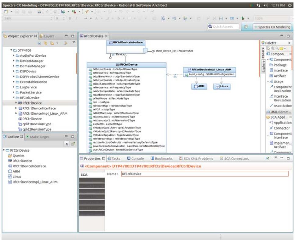
![Spectra CX Modeling - DTP4700::DTP4700::RfCtrlDevice::RfCtrlDevice - Rational® Software Architect\nProject Explorer\nLayers\nDTP4700\nAudioPortDevice\nDeviceManager\nDomainManager\nDSPDevice\nDSPProbeListenerService\nExecutableDevice\nLogService\nPacketService\nRfCtrlDevice\nRFCtrlDevice\nRFCtrlDeviceInterface\nRFCtrlDevicImpl_Linux_ARM\nRFCtrlDevice\ncpld1RevisionType\ncpld2RevisionType\nOutline\nMake Target\nRFCtrlDevice\nQueries\nRFCtrlDevice\nRFCtrlDeviceInterface\nARM\nLinux\nRFCtrlDeviceInterface\nRFCtrlDevice\nRFCtrlDevice\nRFCtrlDevice\nRFCtrlDevice\nRFCtrlDevice\nRFCtrlDevice\nRFCtrlDevice\nRFCtrlDevice\nRFCtrlDevice\nRFCtrlDevice\nRFCtrlDevice\nRFCtrlDevice\nRFCtrlDevice\nRFCtrlDevice\nRFCtrlDevice\nRFCtrlDevice\nRFCtrlDevice\nRFCtrlDevice\nRFCtrlDevice\nRFCtrlDevice\nRFCtrlDevice\nRFCtrlDevice\nRFCtrlDevice\nRFCtrlDevice\nRFCtrlDevice\nRFCtrl device\nRF Ctrl device ctrl : PropertySet\nRF Ctrl Device Interface\nRF Ctrl Device Interface\nRF Ctrl Device Interface\nRF Ctrl Device Interface\nRF Ctrl Device Interface\nRF Ctrl Device Interface\nRF Ctrl Device Interface\nRF Ctrl Device Interface\nRF Ctrl Device Interface\nRF Ctrl Device Interface\nRF Ctrl Device Interface\nRF Ctrl Device Interface\nRF Ctrl Device Interface\nRF Ctrl Device Interface\nRF Ctrl Device Interface\nRF Ctrl Device Interface\nRF Ctrl Device Interface\nRF Ctrl Device Interface\nRF Ctrl Device Interface\nRF Ctrl Device Interface\nRF Ctrl Device Interior\nRF Ctrl Device Interior\nRF Ctrl Device Interior\nRF Ctrl Device Interior\nRF Ctrl Device Interior\nRF Ctrl Device Interior\nRF Ctrl Device Interior\nRF Ctrl Device Interior\nRF Ctrl Device Interior\nRF Ctrl Device Interior\nRF Ctrl Device Interior\nRF Ctrl Device Interior\nRF Ctrl Device Interior\nRF Ctrl Device Interior\nRF Ctrl Device Interior\nRF Ctrl Device Interior\nRF Ctrl Device Interior\nRF Ctrl Device Interior\nRF Ctrl Device Interior\nRF Ctrl Device Interior\nRF Ctrl Device Inner\nRF Ctrl Device Inner\nRF Ctrl Device Inner\nRF Ctrl Device Inner\nRF Ctrl Device Inner\nRF Ctrl Device Inner\nRF Ctrl Device Inner\nRF Ctrl Device Inner\nRF Ctrl Device Inner\nRF Ctrl Device Inner\nRF Ctrl Device Inner\nRF Ctrl Device Inner\nRF Ctrl Device Inner\nRF Ctrl Device Inner\nRF Ctrl Device Inner\nRF Ctrl Device Inner\nRF Ctrl Device Inner\nRF Ctrl Device Inner\nRF Ctrl Device Inner\nRF Ctrl Device Inner\nRF Ctrl Device Internal (RP)\nRF Ctrl Device Internal (RP)\nRF Ctrl Device Internal (RP)\nRF Ctrl Device Internal (RP)\nRF Ctrl Device Internal (RP)\nRF Ctrl Device Internal (RP)\nRF Ctrl Service Internal (RP)\nRF Ctrl Service Internal (RP)\nRF Ctrl Service Internal (RP)\nRF Ctrl Service Internal (RP)\nRF Ctrl Service Internal (RP)\nRF Ctrl Service Internal (RP)\nRF Ctrl Service Internal (RP)\nRF Ctrl Service Internal (RP)\nRF Ctrl Service Internal (RP)\nRF Ctrl Service Internal (RP)\nRF Ctrl Service Internal (RP)\nRF Ctrl Service Internal (RP)\nRF Ctrl Service Internal (RP)\nRF Ctrl Service Internal (RP)\nRF Ctrl Service Internal(RP)\nRF Ctrl Service Internal(RP)\nRF Ctrl Service Internal(RP)\nRF Ctrl Service Internal(RP)\nRF Ctrl Service Internal(RP)\nRF Ctrl Service Internal(RP)\nRF Ctrl Service Internal(RP)\nRF Ctrl Service Internal(RP)\nRF Ctrl Service Internal(RP)\nRF Ctrl Service Internal(RP)\nRF Ctrl Service Internal(RP)\nRF Ctrl Service Internal(RP)\nRF Ctrl Service Internal(RP)\nRF Ctrl Service Internal(RP)\nRF Ctrl Service Internal(RP) \nRVGGA : rvVGA : rvVGA : rvVGA : rvVGA : rvVGA : rvVGA : rvVGA : rvVGA : rvVGA : rvVGA : rvVGA : rvVGA : rvVGA : rvVGA : rvVGA : rvVGA : rvVGA : rvVGA : rvVGA : rvVGA : rvVGA : rvVGA : rvVGA : rvVGA : rvVGA : rvWGA : rvWGA : rvWGA : rvWGA : rvWGA : rvWGA : rvWGA : rvWGA : rvWGA : rvWGA : rvWGA : rvWGA : rvWGA : rvWGA : rvWGA : rvWGA : rvWGA : rvWGA : rvWGA : rvWGA : rvWGA : rvWGA : rvWGA : rvWGA : rvWGA : rvwga : rvwga : rvwga : rvwga : rvwga : rvwga : rvwga : rvwga : rvwga : rvwga : rvwga : rvwga : rvwga : rvwga : rvwga : rvwga : rvwga : rvwga : rvwga : rvwga : rvwga : rvwga : rvwga : rvwga : rvwga : rvwggg: \nRVGGA: \nRVGGA: \nRVGGA: \nRVGGA: \nRVGGA: \nRVGGA: \nRVGGA: \nRVGGA: \nRVGGA: \nRVGGA: \nRVGGA: \nRVGGA: \nRVGGA: \nRVGGA: \nRVGGA: \nRVGGA: \nRVGGA: \nRVGGA: \nRVGGA: \nRVGGA: \nRVGGS: \nRVGGS: \nRVGGS: \nRVGGS: \nRVGGS: \nRVGGS: \nRVGGS: \nRVGGS: \nRVGGS: \nRVGGS: \nRVGGS: \nRVGGS: \nRVGGS: \nRVGGS: \nRVGGS: \nRVGGS: \nRVGGS: \nRVGGS: \nRVGGS: \nRVGGS: \nRVGSG: \nRVGSG: \nRVGSG: \nRVGSG: \nRVGSG: \nRVGSG: \nRVGSG: \nRVGSG: \nRVGSG: \nRVGSG: \nRVGSG: \nRVGSG: \nRVGSG: \nRVGSG: \nRVGSG: \nRVGSG: \nRVGSG: \nRVGSG: \nRVGSG: \nRVGSG: \nRVGSS: \nRVGSS: \nRVGSS: \nRVGSS: \nRVGSS: \nRVGSS: \nRVGSS: \nRVGSS: \nRVGSS: \nRVGSS: \nRVGSS: \nRVGSS: \nRVGSS: \nRVGSS: \nRVGSS: \nRVGSS: \nRVGSS: \nRVGSS: \nRVGSS: \nRVGSS: \nRVGSG: \nRVGSG: \nRVGSG: \nRVGSG: \nRVGSG: \nRVGSG: \nRVGSG: \nRVGSG: \nRVGSG: \nRVGSG: \nRVGSG: \nRVGSG: \nRVGSG: \nRVGSG: \nRVGSG: \nRVGSG: \nRVGSG: \nRVGSG: \nRVGSG: \nRVGSC: \nRVGSC: \nRVGSC: \nRVGSC: \nRVGSC: \nRVGSC: \nRVGSC: \nRVGSC: \nRVGSC: \nRVGSC: \nRVGSC: \nRVGSC: \nRVGSC: \nRVGSAGS(fcel)AVICIP 3.5.1.1.1.1.1.1.1.1.1.1.1.1.1.1.1.1.1.1.1.1.1.1.1.1.1.1.1.1.1.1.1.1.1.1.1.1.1.1.1.1.1.1.1.1.1.1.1.1.1.1.(nl)(Component) DTP4700::DTP4700::RfCtrlDevice::RfCtrlDevice](.spectra-dtp4700-userguide/9f289048fce8d8774e33b339aa69febde239e1b7c9f402a1e36da0917c9be1e5.jpg)

Figure 11 RfCtrlDevice component definition
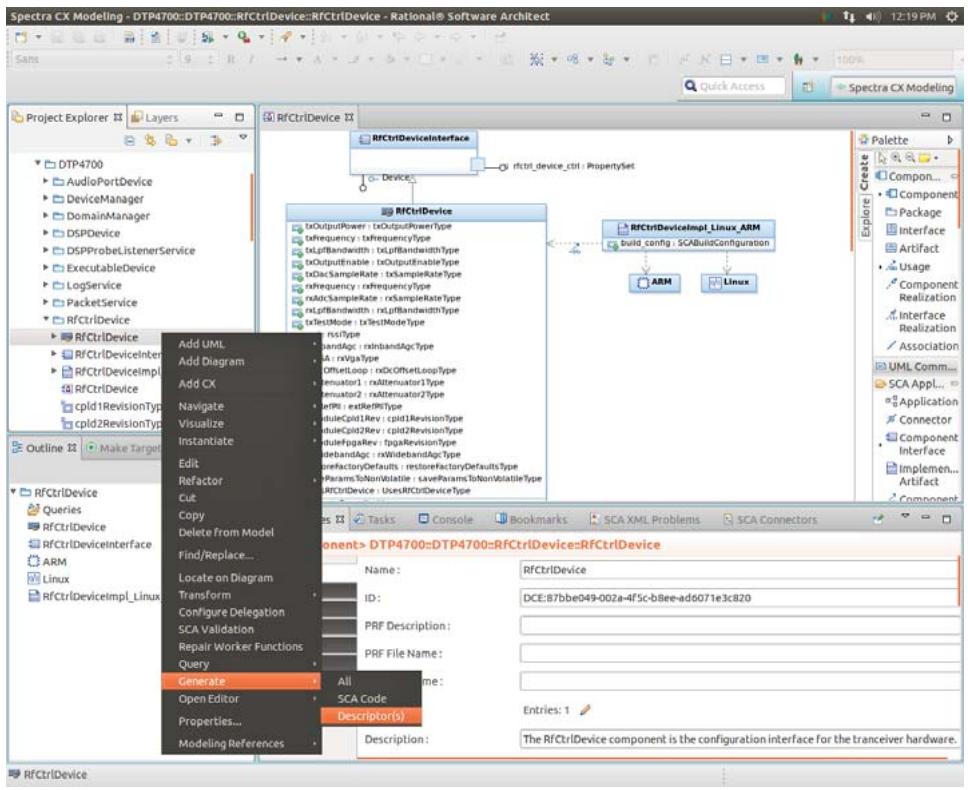
![Spectra CX Modeling - DTP4700::DTP4700::RfCtrlDevice::RfCtrlDevice - Rational® Software ArchRect\nProject Explorer XX Layers\nDTP4700 AudioPortDevice DeviceManager DomainManager DSPDevice DSPProbeListenerService ExecutableDevice LogService PacketService PacketService RFCtrlDevice RFCtrlDevice RFCtrlDeviceInterface RFCtrlDeviceImpl RFCtrlDeviceImpl Linux ARM\nAdd UML Add Diagram Add CX Navigate Visualize Instantiate Edit Refactor Cut Copy Delete from Model Find/Replace... Locate on Diagram Transform Configure Delegation SCA Validation Repair Worker Functions Query Generate Open Editor Properties... Modeling References RFCtrlDevice Interface RFCtrlDevice Interface RFCtrlDevice Interface RFCtrlDevice Interface RFCtrlDevice Interface RFCtrlDevice Interface RFCtrlDevice Interface RFCtrlDevice Interface RFCtrlDevice Interface RFCtrlDevice Interface RFCtrlDevice Interface RFCtrlDevice Interface RFCtrlDevice Interface RFCtrlDevice Interface RFCtrlDevice Interface RFCtrlDevice Interface RFCtrlDevice Interface RFCtrlDevice Interface RFCtrlDevice Interface RFCtrlDevice Interface RFCtrlDevice Interface RFCtrlDevice Interface RFCtrlDevice Interface RFCtrlDevice Interface RFCtrlDevice Interface RFCtrlDevice Interior RFCtrlDevice Interior RFCtrlDevice Interior RFCtrlDevice Interior RFCtrlDevice Interior RFCtrlDevice Interior RFCtrlDevice Interior RFCtrlDevice Interior RFCtrlDevice Interior RFCtrlDevice Interior RFCtrlDevice Interior RFCtrlDevice Interior RFCtrlDevice Interior RFCtrlDevice Interior RFCtrlDevice Interior RFCtrlDevice Interior RFCtrlDevice Interior RFCtrlDevice Interior RFCtrlDevice Interior RFCtrlDevice Interior RFCtrlDevice Interior RFCtrlDevice Interior RFCtrlDevice Interior RFCtrlDevice Interior RFCtrlDevice Interior RFCtrlDevice II RfctrlDeviceII RfctrlDeviceII RfctrlDeviceII RfctrlDeviceII RfctrlDeviceII RfctrlDeviceII RfctrlDeviceII RfctrlDeviceII RfctrlDeviceII RfctrlDeviceII RfctrlDeviceII RfctrlDeviceII RfctrlDeviceII RfctrlDeviceII RfctrlDeviceII RfctrlDeviceII RfctrlDeviceII RfctrlDeviceII RfctrlDeviceII RfctrlDeviceII RfctrlDeviceIII RfctrlDeviceIII RfctrlDeviceIII RfctrlDeviceIII RfctrlDeviceIII RfctrlDeviceIII RfctrlDeviceIII RfctrlDeviceIII RfctrlDeviceIII RfctrlDeviceIII RfctrlDeviceIII RfctrlDeviceIII RfctrlDeviceIII RfctrlDeviceIII RfctrlDeviceIII RfctrlDeviceIII RfctrlDeviceIII RfctrlDeviceIII RfctrlDeviceIII RfctrlDeviceIII RfctrlDevice III RfctrlDevice III RfctrlDevice III RfctrlDevice III RfctrlDevice III RfctrlDevice III RfctrlDevice III RfctrlDevice III RfctrlDevice III RfctrlDevice III RfctrlDevice III RfctrlDevice III RfctrlDevice III RfctrlDevice III RfctrlDevice III RfctrlDevice III RfctrlDevice III RfctrlDevice III RfctrlDevice III RfctrlDevice III RfctrlDevice II RfctrlDevice II RfctrlDevice II RfctrlDevice II RfctrlDevice II RfctrlDevice II RfctrlDevice II RfctrlDevice II RfctrlDevice II RfctrlDevice II RfctrlDevice II RfctrlDevice II RfctrlDevice II RfctrlDevice II RfctrlDevice II RfctrlDevice II RfctrlDevice II RfctrlDevice II RfctrlCode Description: All 5CA Code Descriptor(s) Description: The RFCtrlDevice component is the configuration interface for the trancever hardware.\nRFCtrlDevice Interface RFCtrlDevice Interface RFCtrlDevice Interface RFCtrlDevice Interface RFCtrlDevice Interface RFCtrlDevice Interface RFCtrlDevice Interface RFCtrlDevice Interface RFCtrlDevice Interface RFCtrlDevice Interface RFCtrlDevice Interface RFCtrlDevice Interface RFCtrlDevice Interface RFCtrlDevice Interface RFCtrlDevice Interface RFCtrlCode Description: All 5CA Code Descriptor(s) Description: The RFCtrlDevice Component is the configuration interface for the trancever hardware.](.spectra-dtp4700-userguide/77003de252950e0ce5ced993709479f94e52bfbd8bb130b0e8e52c24a4f125e8.jpg)

Figure 12 Generating Descriptors

Step 4: Right-click the RfCtrlDevice model element either by using the model element (structural realisation) displayed in the diagram or in the Project Explorer view, and choose Generate > Descriptor(s) from the menu, as shown in Figure 12. Notice that this procedure creates a folder DTP4700\_src in the workspace to contain the generated descriptor artefacts, and that the model is validated prior to generating the required files.

Step 5: Expand the DTP4700\_src descriptors folder in the Project Explorer view to display the generated descriptor artefacts for the DTP4700 project. Double-click on the profile descriptor for the RfCtrlDevice component (RfCtrlDevice.prf.xml) to view the file contents in Spectra. Using the file editor search for the text string ‘txFrequency’ to examine the XML elements describing the property, including the assigned default value. This is illustrated in Figure 13.
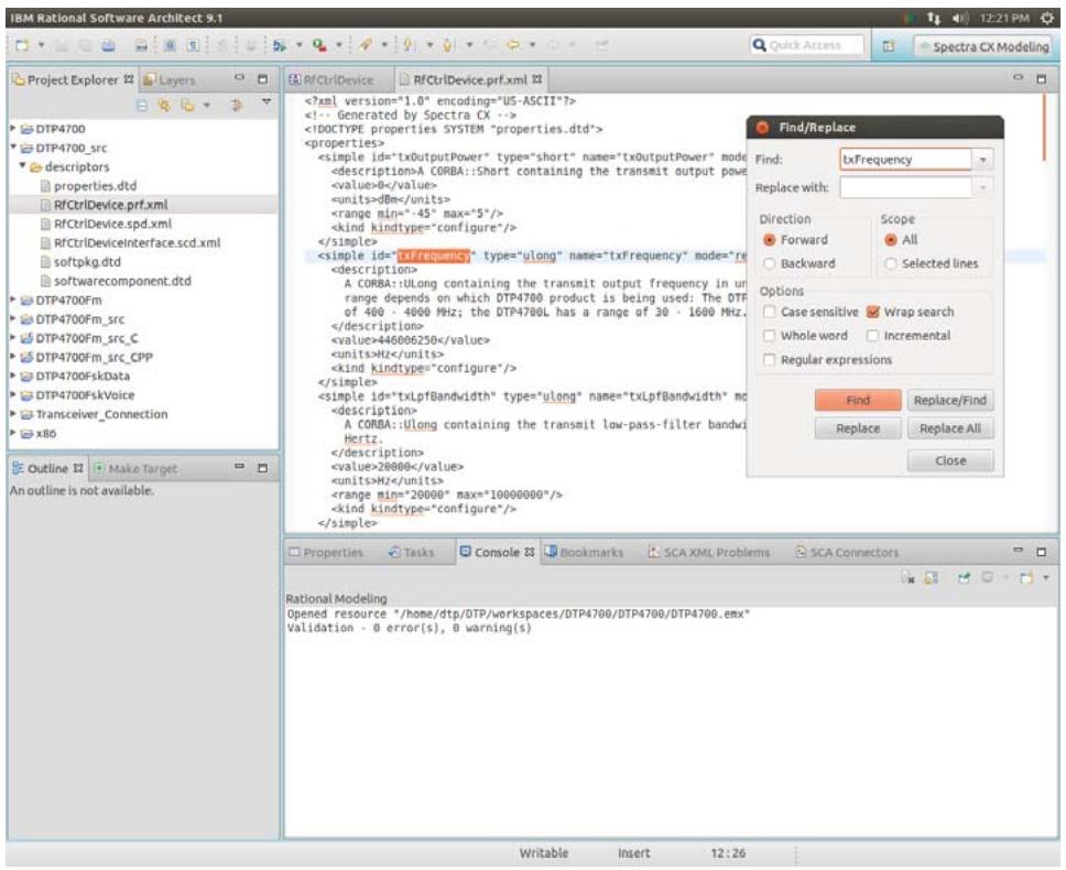
![IBM Rational Software Architect 9.1\nProject Explorer\nLayers\nDTP4700\nDTP4700_src\ndescriptors\nproperties.dtd\nRFCtrlDevice.prf.xml\nRFCtrlDevice.spd.xml\nRFCtrlDeviceinterface.scd.xml\nsoftpkg.dtd\nsoftwarecomponent.dtd\nDTP4700Fm\nDTP4700Fm_src\nDTP4700Fm_src_C\nDTP4700Fm_src_CPP\nDTP4700FskData\nDTP4700FskVoice\nTransceiver_Connection\nx86\nOutline 32\nMake Target\nAn outline is not available.\nRFCtrlDevice\nRFCtrlDevice.prf.xml\n(?xml version='1.0' encoding='US-ASCII'?)\n(!-- Generated by Spectra CX --)\n(!DOCTYPE properties SYSTEM 'properties.dtd')\n(properties)\n    (simple id='txOutputPower' type='short' name='txOutputPower' mode='value')A CORBA::Short containing the transmit output power\n    (value)0(/value)\n    (units)dBm(/units)\n    (range min=-.45' max='5'/)\n    (kind kindtype='configure'/)\n    (/simple)\n    (simple id='txfrequency' type='ulong' name='txfrequency' mode='reset')\n    (description)\n        A CORBA::ulong containing the transmit output frequency in un range depends on which DTP4700 product is being used: The DTP of 400 - 4000 MHz; the DTP4700L has a range of 30 - 1600 MHz.\n    (/description)\n    (value)46006250(/value)\n    (units)Hz(/units)\n    (kind kindtype='configure'/)\n    (/simple)\n    (simple id='txLpfBandwidth' type='ulong' name='txLpfBandwidth' mode='value')\n    (description)\n        A CORBA::ulong containing the transmit low-pass-filter bandwidth Hertz.\n    (/description)\n    (value)28000(/value)\n    (units)Hz(/units)\n    (range min=20000' max=10000000'/)\n    (kind kindtype='configure'/)\n    (/simple)\nFind/Replace\nFind:\ntxFrequency\nReplace with:\nDirection\nForward\nBackward\nScope\nAll\nSelected lines\nOptions\nCase sensitive Wrap search\nWhole word Incremental\nRegular expressions\nFind Replace/Find\nReplace Replace All Close\nProperties Tasks Console 33 Bookmarks SCA XML Problems SCA Connectors\nRational Modeling\nOpened resource '/home/dtp/OTP/workspaces/DTP4700/DTP4700/DTP4700.emx'\nValidation - 0 error(s), 0 warning(s)\nWritable Insert 12:26](.spectra-dtp4700-userguide/af4a25145db7c1f1dc8b4c0504bfc255df6eab4a58cdaf853407bcf1d0542b36.jpg)

Figure 13 Profile descriptor

# 4.5.2 Radio Frequency/Transceiver Sub-system

The hardware components and parameters available for controlling the RF/Transceiver sub-system of the Thunder are illustrated in Figure 14.
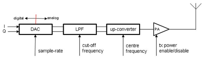

![The flowchart depicts a signal processing chain arranged horizontally from left to right.\n\n**Blocks:**\n*   **DAC**: A rectangular block on the far left.\n*   **LPF**: A rectangular block connected to the right of the DAC.\n*   **up-converter**: A rectangular block connected to the right of the LPF.\n*   **PA**: A triangular block connected to the right of the up-converter.\n*   **Antenna**: A symbol on the far right connected to the output of the PA.\n\n**Connections and Labels:**\n*   **DAC**:\n    *   Inputs labeled **I** and **Q** enter the left side.\n    *   Above the block, an arrow points left labeled **digital** and an arrow points right labeled **analog**.\n    *   An arrow points upward into the bottom labeled **sample-rate**.\n*   **LPF**:\n    *   Connected to the output of the DAC.\n    *   An arrow points upward into the bottom labeled **cut-off frequency**.\n*   **up-converter**:\n    *   Connected to the output of the LPF.\n    *   An arrow points upward into the bottom labeled **centre frequency**.\n*   **PA**:\n    *   Connected to the output of the up-converter.\n    *   An arrow points upward into the bottom labeled **tx: power enable/disable**.](.spectra-dtp4700-userguide/ca3fbb133e5e1e658ad707bd2724a69b740143e8f99750f0aad71d7975284f10.jpg)

![Based on the provided image, here is the accurate description of the flowchart:\n\n**Labeled Blocks (from left to right):**\n1.  **digital tuner** (rectangular box)\n2.  **ADC** (rectangular box)\n3.  **RXVGA** (rectangular box)\n4.  **LPF** (rectangular box)\n5.  **down-converter** (rectangular box)\n6.  **PA** (triangle pointing right)\n7.  **LNA** (triangle pointing right)\n8.  **Antenna** (symbol at the top right)\n\n**Connections and Labels:**\n*   **digital tuner**: Connected to **ADC** via a double line. To its left are two arrows pointing left labeled **I** and **Q**. Below it is an arrow pointing up from **i/o ctrl**.\n*   **ADC**: Connected to **digital tuner** (left) and **RXVGA** (right) via double lines. Above it is the text **digital** with a left-pointing arrow and **analog** with a right-pointing arrow, separated by a vertical red line. Below it is an arrow pointing up from **sample-rate**.\n*   **RXVGA**: Connected to **ADC** and **LPF** via double lines.\n*   **LPF**: Connected to **RXVGA** and **down-converter** via double lines. Below it is an arrow pointing up from **cut-off frequency**.\n*   **down-converter**: Connected to **LPF** (left) and **PA** (right) via a single line. Below it is an arrow pointing up from **centre frequency**.\n*   **PA**: Connected to **down-converter** and **LNA** via a single line. Below it is an arrow pointing up from **att**.\n*   **LNA**: Connected to **PA** and the Antenna via a single line. Below it is an arrow pointing up from **att**.](.spectra-dtp4700-userguide/5cf62fbbafcd81804c1441be725f30606b34127aa929aa6a6362aaa77976cf2f.jpg)

Figure 14 RF/Transceiver sub-system and Control Parameters

Referring to Figure 14, the software interface to the DAC (Tx) and the ADC (Rx) to the baseband domain is provided by a device driver controlling an FPGA device mounted on the digital board of the Thunder (See Figure 2 on page 6). Control functionality for the RF/Transceiver sub-system is implemented in a separate FPGA device mounted on the RF board which is also controlled using the driver from the GPP. As described earlier in this chapter, the WfFPGAProxy and RfCtrlDevice components provide the necessary SCA abstraction for the device driver, where, in the case of data, the WfFPGAProxy is capable of sending/receiving interleaved 16-bit sampled complex baseband signal data to/from the RF/Transceiver sub-system (See Section 6.3, Connecting Waveform with Platform, on page 51, for more information).

The digital tuner is provided as a separate processing unit connected to the Wf FPGA. By default, signals are routed through the digital tuner. Alternatively, the digital tuner can be bypassed.

The Thunder RF/Transceiver sub-system hardware includes an Automatic Gain Control (AGC) function which supports two control loops:

• wide-band – affecting the Rx signal upstream of the low-pass filter (LPF) by attenuation of the signal at the Power Amplification (PA) phase (illustrated as ‘att’ in Figure 14).
• narrow-band – affecting the Rx signal downstream of the low-pass filter (LPF) by parameters controlling the Rx Variable Gain Amplifier (RXVGA).

The AGC function can be disabled in either mode which assumes maximum gain.

The various control parameters required to control the RF/Transceiver sub-system, as shown in Figure 14, are exposed as SCA properties assigned to the RfCtrlDevice component provided as part of the DTP4700 SCA platform. Table 4 provides an overview of those properties directly affecting the RF/Transceiver sub-system control.

Table 4 SCA Properties for RfCtrlDevice Component

<table><tr><td>SCA Property Name</td><td>SCA Property Type/Action</td><td>Units/Default Value</td><td>Function/range</td></tr><tr><td>txOutPutPower</td><td>Short/Configure</td><td>dBm/0</td><td>Tx output power -45 to +5 dBm range</td></tr><tr><td>txFrequency</td><td>Ulong/Configure</td><td>Hz/446006250</td><td>Tx output frequency</td></tr><tr><td>txLpfBandwidth</td><td>Ulong/Configure</td><td>Hz/20000</td><td>Tx lowpass filter bandwidth (cut-off frequency)</td></tr><tr><td>txOutputEnable</td><td>Boolean/Configure</td><td>false</td><td>Enable Tx output</td></tr><tr><td>txDacSampleRate</td><td>Ulong/Configure</td><td>sps/48000</td><td>DAC sample rate</td></tr><tr><td>rxFrequency</td><td>Ulong/Configure</td><td>Hz/446006310</td><td>Rx input frequency</td></tr><tr><td>rxAdcSampleRate</td><td>Ulong/Configure</td><td>sps/6144000</td><td>ADC sample rate</td></tr><tr><td>rxLpfBandwidth</td><td>Ulong/Configure</td><td>Hz/20000</td><td>Rx lowpass filter bandwidth (cut-off frequency)</td></tr><tr><td>rxInbandAgc</td><td>Boolean/Configure</td><td>true</td><td>Enable automatic gain control (AGC)</td></tr><tr><td>rxVGA</td><td>Short/Configure</td><td>dB/0</td><td>Gain, only settable if rxInbandAgc is disabled /0-40</td></tr><tr><td>rxDcOffsetLoop</td><td>Boolean/Configure</td><td>true</td><td>DC offset compensation</td></tr><tr><td>rxAttenuator1</td><td>Short/Configure</td><td>dBm/31</td><td>Only settable if rxWidebandAgc is disabled</td></tr><tr><td>rxAttenuator2</td><td>Short/Configure</td><td>dBm/31</td><td>Only settable if rxWidebandAgc is disabled</td></tr><tr><td>extRefPII</td><td>Boolean/Configure</td><td>false</td><td>External ref phase lock loop</td></tr><tr><td>rxWidebandAgc</td><td>Boolean/Configure</td><td>true</td><td>Enable Rx wideband automatic gain control</td></tr></table>

# 4.5.2.1 The Digital Tuner

The digital tuner is used to decimate the sample rate and sharply filter the input signal, i.e., reduce or eliminate aliasing caused by the ADC process1 . By default, the digital tuner's decimation rate is 128, and the decimation filter cut-off frequency is 0.8 PI radians/sample at the decimated rate.

The decimation rate and filter cut-off can be changed by programming the digital tuner using the following method,

Step 1: Read the current configuration into memory by opening the device /dev/ad6620, reading into a buffer, and typecasting the buffer to "struct AD6620\_PARAMETERS\_STRUCT" (defined in ad6620\_ioctl.h).

Step 2: The parameters can be changed as required then written back to the device.

To bypass the digital tuner, set bit 13 to 0 in Wf FPGA register 0x48. Alternatively, to route the signal through the digital tuner, set bit 13 to 1 in Wf FPGA register 0x48.

This can be achieved programmatically as follows:

```c
#include &lt;wf_fpga/wf_fpga_ioctl.h&gt;

int fd;

fd = open("/dev/wf_fpga", O_RDWR);
if( fd &lt; 0 )
{
    // Handle error
}

T_WF_FPGA_MEM_IO req;
req.ctrl_reg = 0x48;

if( ioctl(fd, WF_FPGA_MEM_IO_READ, &req) != 0 )
{
    // Handle error
}

// Uncomment the appropriate line.
// req.val = (req.val & ~(0x2000)); // Bypass tuner
// req.val = (req.val & ~(0x2000)) | 0x0200; // Route through tuner

if( ioctl(fd, WF_FPGA_MEM_IO_WRITE, &req) != 0 )
{
    // Handle error
}
```

# 4.5.2.2 Changing Sample Rates

This section outlines the capabilities of the DTP4700 for tuning the sample rates of digital signals to meet various application demands.

# 4.5.2.2.1 Baseband Tx Sample Rate

The Tx sample rate is controlled using the txSampleRate configure property on the RfCtrlDevice (see Table 4).

The baseband Tx sample rate can be changed programmatically via the configure operation exposed by the RfCtrlDevice through its supports interface and the rfctrl\_device\_ctrl provides port. To change the rate programatically from a waveform application a connection must be made to the rfctrl\_device\_ctrl port as application components are unable to connect directly to a supports interface on an SCA Device.

As an example the AssemblyController component from the DTP4700Fm example waveform controls the sample rate from the \_CF\_Resource\_start operation through its RfCtrlDeviceCtrl uses port which is connected to the rfctrl\_device\_ctrl provides port on the RfCtrlDevice. The code to change the sample rate is as follows:

```cpp
CF::Properties p;
p.length(1);
p[0].id = "txSampleRate";
p[0].value &lt;&lt;= (CORBA::ULong) 48000; // samples per second
RfCtrlDeviceCtrl_-&gt;configure(p);
```

# 4.5.2.2.2 Baseband Rx Sample Rate

The baseband Rx sample rate is controlled using the rxSampleRate configure property on the RfCtrlDevice (see Table 4). However, this value must be considered in the context of the additional parameters set on the digital tuner where t h i s i s n o t b y p a s s e d . T h e a c t u a l s a m p l e r a t e i s d e t e r m i n e d b y t h e rxAdcSampleRate configure property divided by the decimation rate set on the digital tuner. In addition, the cut-off frequency set on the digital tuner is expressed in terms of PI radians per sample, therefore this must be adjusted to reflect the ratio of sample rate and frequency required for the application.

The baseband Rx sample rate can be changed programmatically via the configure operation exposed by the RfCtrlDevice through its supports interface and the rfctrl\_device\_ctrl provides port. To change the rate programatically from a waveform application a connection must be made to the rfctrl\_device\_ctrl port as application components are unable to connect directly to a supports interface on an SCA Device.

As an example the AssemblyController component from the DTP4700Fm example waveform controls the sample rate from the \_CF\_Resource\_start operation through its RfCtrlDeviceCtrl uses port which is connected to the rfctrl\_device\_ctrl provides port on the RfCtrlDevice. The code to change the sample rate is as follows:

```txt
CF::Properties p;
p.length(1);
p[0].id = "rxSampleRate";
p[0].value &lt;&lt;= (CORBA::ULong)(48000 * 128); // samples per second
RfCtrlDeviceCtrl_-&gt;configure(p);
```

# 4.5.2.2.3 Audio Sample Rate

The AudioPortDevice component supplied as part of the DTP4700 SCA platform provides an abstraction of the Advanced Linux Sound Architecture (ALSA) drivers installed as part of the Linux operating system kernel running on the ARM core of the OMAP processing unit.

The audio sample rate set on the ALSA driver is modelled as a property type (named ‘rate’) that has the SCA property kind set as execparam. Consequently, the core framework will interpret the AudioPortDevice rate property as an executable parameter for use when the component is first instantiated. The property is not configurable and its value can only be changed at the modelling (descriptor) level. This is achieved in the same way as described in Section 4.5.1 for changing the default values of configurable properties. The default value for the sample rate used by the AudioPortDevice is 16 kilo-samples/sec.

# CHAPTER

# Sample Waveforms

A number of Spectra CX models are included in the software package supporting the DTP4700 product. These provide sample application assemblies (waveforms) for use in platform validation and testing procedures, and for general purpose SCA training.

Using Spectra CX, the sample models can be deployed as waveform applications to the DTP4700 SCA platform as described in Chapter 8.

# 5.1 Restrictions on the use of the DSP

![The image displays a red triangular warning sign with a thick red border. Inside the triangle, there is a black exclamation point. Below the exclamation point is a small black diamond.](.spectra-dtp4700-userguide/b7345dd4793eb74acb2a791ce875576a9e41f1d721b95dd5a9a6fc5fe245459f.jpg)

The DTP4700 does not support dynamic reconfiguration of the DSP core of the OMAP device. Consequently, a restriction is imposed whereby a single loadable image containing all the application and kernel symbols is loaded and executed only once. The approach adopted for the DTP4700, in SCA terms, is to configure a ResourceFactory to co-locate all components required for the DSP, and package the ResourceFactory together with kernel libraries as a single image using the DSP tool-chain. At the time of deployment, an SCA device running on the ARM core as part of the DTP4700 SCA platform is used as a proxy to manage the lifecycle of the DSP image. This approach is entirely conformant with the SCA.

# 5.2 Analog Audio (DTP4700Fm)

The functional parts of the DTP4700Fm waveform consists of four SCA components (implementation of the SCA Resource interface) used to transmit and receive Frequency Modulated (FM) analog audio signals over the air interface (RF) of the Thunder hardware platform. The modulation and demodulation functions are implemented in C for deployment on the DSP processor and the up-sampling and down-sampling functions are implemented in C++ for deployment on the ARM processor. Figure 15 shows the Spectra CX model of the waveform.
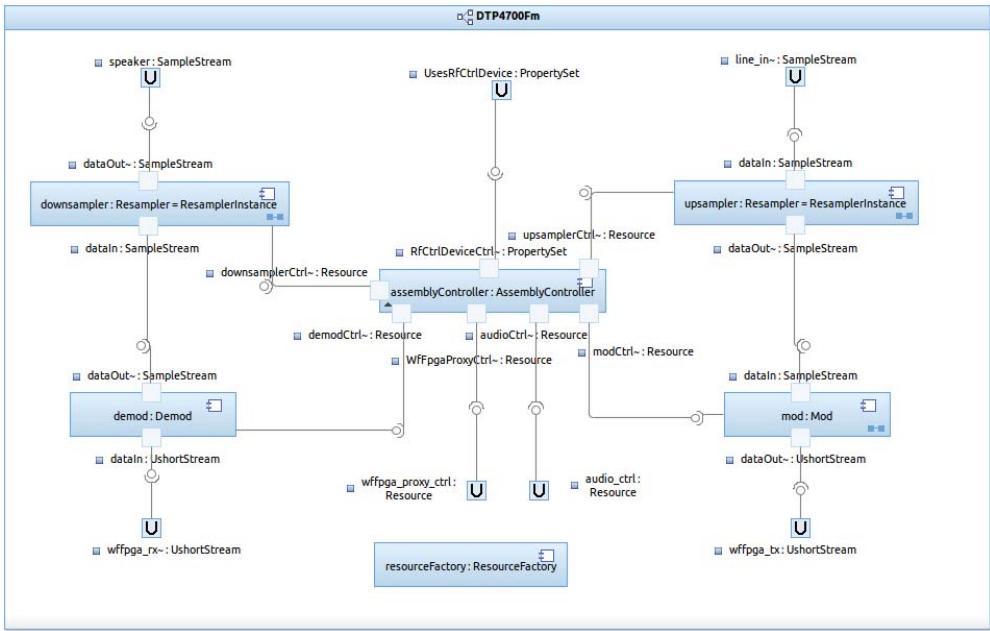
![Based on the provided flowchart, here is the accurate description of the labeled blocks and connections:\n\n**Labeled Blocks and Entities:**\n*   `speaker : SampleStream`\n*   `downsampler : Resampler = ResamplerInstance`\n*   `demod : Demod`\n*   `wffpga_rx~ : UshortStream`\n*   `UsesRfCtrlDevice : PropertySet`\n*   `assemblyController : AssemblyController`\n*   `resourceFactory : ResourceFactory`\n*   `line_in~ : SampleStream`\n*   `upsampler : Resampler = ResamplerInstance`\n*   `mod : Mod`\n*   `wffpga_tx~ : UshortStream`\n\n**Labels and Connection Points:**\n*   `dataOut~ : SampleStream` (appears twice)\n*   `dataIn~ : SampleStream` (appears twice)\n*   `dataIn~ : UshortStream`\n*   `dataOut~ : UshortStream`\n*   `RfCtrlDeviceCtrl~ : PropertySet`\n*   `downsamplerCtrl~ : Resource`\n*   `demodCtrl~ : Resource`\n*   `wffpga_proxy_ctrl : Resource`\n*   `audioCtrl~ : Resource`\n*   `modCtrl~ : Resource`\n*   `upsamplerCtrl~ : Resource`\n*   `audio_ctrl : Resource`\n\n**Connections:**\n*   **Left Column (Downstream Path):**\n    *   `speaker : SampleStream` connects to `downsampler : Resampler = ResamplerInstance` via `dataOut~ : SampleStream`.\n    *   `downsampler : Resampler = ResamplerInstance` connects to `demod : Demod` via `dataIn~ : SampleStream`.\n    *   `demod : Demod` connects to `wffpga_rx~ : UshortStream` via `dataIn~ : UshortStream`.\n\n*   **Right Column (Upstream Path):**\n    *   `line_in~ : SampleStream` connects to `upsampler : Resampler = ResamplerInstance` via `dataIn~ : SampleStream`.\n    *   `upsampler : Resampler = ResamplerInstance` connects to `mod : Mod` via `dataOut~ : SampleStream`.\n    *   `mod : Mod` connects to `wffpga_tx~ : UshortStream` via `dataOut~ : UshortStream`.\n\n*   **Center (Assembly and Control Connections):**\n    *   `UsesRfCtrlDevice : PropertySet` connects to `assemblyController : AssemblyController`.\n    *   `RfCtrlDeviceCtrl~ : PropertySet` is associated with the connection to `assemblyController : AssemblyController`.\n    *   `downsampler : Resampler = ResamplerInstance` connects to `assemblyController : AssemblyController` via `downsamplerCtrl~ : Resource`.\n    *   `demod : Demod` connects to `assemblyController : AssemblyController` via `demodCtrl~ : Resource`.\n    *   `demod : Demod` connects to `assemblyController : AssemblyController` via `wffpga_proxy_ctrl : Resource`.\n    *   `mod : Mod` connects to `assemblyController : AssemblyController` via `modCtrl~ : Resource`.\n    *   `upsampler : Resampler = ResamplerInstance` connects to `assemblyController : AssemblyController` via `upsamplerCtrl~ : Resource`.\n    *   `assemblyController : AssemblyController` connects to `audio_ctrl : Resource` via `audioCtrl~ : Resource`.\n\n*   **Standalone Entity:**\n    *   `resourceFactory : ResourceFactory` is located at the bottom center and has no visible connections.](.spectra-dtp4700-userguide/07d9efb4ccc3c25faa3b1ba47fa3723634cd0f85e3684d80f57d02a31abd58e2.jpg)

Figure 15 DTP4700Fm Application Assembly model

The DTP4700Fm application assembly illustrates the use-case where the mod and demod component instances are co-located together with a resourceFactory such that these can be deployed as a single binary image to the DSP.

mod: model element represents an instance of the Mod component definition. The component instance (implementation of Resource) receives audio samples from the upsampler component instance and performs a frequency modulation on the data pushing resulting complex I&Q samples to the WfFpgaProxy component instance running on the platform.

demod: model element represents an instance of the Demod component definition. The component instance (implementation of Resource) receives complex I&Q samples from the WfFpgaProxy component instance running on the platform and performs a frequency de-modulation on the data pushing resulting audio sample data to the downsampler component instance.

upsampler: model element represents an instance of the Resampler component definition that performs rate conversion. The upsampler instance re-samples the signal received from the AudioPortDevice component running on the platform from 16 to 48 kilo-samples/sec pushing resulting samples to the mod component instance.

downsampler: model element represents an instance of the Resampler component definition that performs rate conversion. The downsampler instance re-samples the signal received from the demod component instance f r o m 4 8 t o 1 6 k i l o - s a m p l e s / s e c p u sh i n g r e s u l t i n g s a m p l e s t o t h e AudioPortDevice component running on the platform.

assemblyController: model element represents an instance of the AssemblyController component definition. Generally, the SCA requires that an assembly controller is used to delegate lifecycle operations (e.g., start/stop) to connected application components using the Resource interface. Consequently, in the case of the Analog FM application, uses port connections to all other components are modelled, including, where appropriate, with platform components using a uses device relationship.

NOTE: The general convention is adopted for the DTP4700 models where the text ‘Ctrl’ is appended to uses port names denoting components connected to the assembly controller. Note also that in the case where connections to platform components are required, an equivalent provides port is required on the platform component to represent the platform side of the resource connection.

r e s o u r c e F a c t o r y : m o d e l e l e m e n t r e p r e s e n t s a n i n s t a n c e o f t h e ResourceFactory component definition. This provides a mechanism based on a factory design pattern for co-locating runtime instances of assigned Resource types with the resourceFactory itself. In the case of the Analog FM application, this component creates the mod and demod components.

# 5.3 Digital Audio (DTP4700FskVoice)

The DTP4700FskVoice waveform can be used to transmit and receive digital audio signals over the air interface (RF) of the Thunder hardware platform.

The functional parts of the waveform consist of four SCA components (implementation of SCA Resource interface) to provide a simple digital voice link. The encoding/modulation and decoding/demodulation functions are implemented in C for deployment on the DSP processor. Figure 16 shows the Spectra CX model of the waveform.
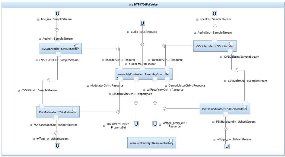
![The diagram depicts a signal processing architecture titled 'DTP4700FskVoice'. It consists of three main sections: a left-side encoding/modulation path, a right-side decoding/demodulation path, and a central controller.\n\n**Labeled Blocks:**\n*   **Left Path:** `line_in-: SampleStream`, `AudioIn-: SampleStream`, `cVSDEncoder : CVSDEncoder`, `CVSDBitsOut-: SampleStream`, `CVSDBitsIn-: SampleStream`, `FSKModulator : FSKModulator`, `FSKBasebandOut-: UshortStream`, `wffpga_tx-: UshortStream`.\n*   **Right Path:** `speaker-: SampleStream`, `AudioOut-: SampleStream`, `cVSDDecoder : CVSDDecoder`, `CVSDBitsIn-: SampleStream`, `CVSDBitsOut-: SampleStream`, `FSKDemodulator : FSKDemodulator`, `FSKBasebandIn-: UshortStream`, `wffpga_rx-: UshortStream`.\n*   **Central Controller:** `assemblyController : AssemblyController` (containing internal labels: `EncoderCtrl-: Resource`, `audioCtrl-: Resource`, `DecoderCtrl-: Resource`, `ModulatorCtrl-: Resource`, `RFctrlDeviceCtrl-: PropertySet`, `WfFpgaProxyCtrl-: PropertySet`, `DemodulatorCtrl-: Resource`).\n*   **Controller Inputs/Outputs:** `audio_ctrl-: Resource`, `UsesRfCtrlDevice : PropertySet`, `wffpga_proxy_ctrl : Resource`.\n*   **Other:** `resourceFactory : ResourceFactory`.\n*   **Interface Ports:** Multiple blocks labeled `U`.\n\n**Connections:**\n*   **Input/Encoding Flow:** `line_in-: SampleStream` connects to `AudioIn-: SampleStream`, which connects to `cVSDEncoder : CVSDEncoder`. The encoder outputs to `CVSDBitsOut-: SampleStream`, which connects to `CVSDBitsIn-: SampleStream`, feeding into `FSKModulator : FSKModulator`. The modulator outputs `FSKBasebandOut-: UshortStream`, which connects to `wffpga_tx-: UshortStream`.\n*   **Output/Decoding Flow:** `speaker-: SampleStream` connects to `AudioOut-: SampleStream`, which connects to `cVSDDecoder : CVSDDecoder`. The decoder outputs `CVSDBitsIn-: SampleStream`, which connects to `CVSDBitsOut-: SampleStream`, feeding into `FSKDemodulator : FSKDemodulator`. The demodulator outputs `FSKBasebandIn-: UshortStream`, which connects to `wffpga_rx-: UshortStream`.\n*   **Controller Connections:** `audio_ctrl-: Resource` connects to `assemblyController : AssemblyController`. The controller manages the system via several labeled connections:\n    *   To `cVSDEncoder : CVSDEncoder` via `EncoderCtrl-: Resource`.\n    *   To `cVSDDecoder : CVSDDecoder` via `DecoderCtrl-: Resource`.\n    *   To `FSKModulator : FSKModulator` via `ModulatorCtrl-: Resource`.\n    *   To `FSKDemodulator : FSKDemodulator` via `DemodulatorCtrl-: Resource`.\n    *   To `UsesRfCtrlDevice : PropertySet` via `RFctrlDeviceCtrl-: PropertySet`.\n    *   To `wffpga_proxy_ctrl : Resource` via `WfFpgaProxyCtrl-: PropertySet`.\n*   **External Interfaces:** `wffpga_tx-: UshortStream`, `UsesRfCtrlDevice : PropertySet`, `wffpga_proxy_ctrl : Resource`, and `wffpga_rx-: UshortStream` each connect to a `U` interface block. Input `U` blocks connect to `line_in-: SampleStream`, `audio_ctrl-: Resource`, and `speaker-: SampleStream`.\n*   **Standalone:** `resourceFactory : ResourceFactory` is an isolated block at the bottom.](.spectra-dtp4700-userguide/27443cc27560dbd8027aa43cd6657ba7d6c919b50abf86005ac6d61902273c31.jpg)

Figure 16 DTP4700FskVoice Application Assembly model

cVSDEncoder: model element represents an instance of the CVSDEncoder component definition. The encoder accepts a digitised voice signal from the AudioPortDevice component running on the platform and encodes it using Continuously Variable Slope Delta-modulation (CVSD). The voice input is 16 kilo-samples/sec, 16 bit linear quantisation. The syllabic integrator time constant is 3.5 milliseconds. The reconstruction integrator time constant is 620 us. The 16 kilo-bits/sec encoded output is pushed to the fSKModulator component instance.

fSKModulator: model element represents an instance of the FSKModulator component definition. The fSKModulator modulates a CVSD bit stream received from the cVSDEncoder using Frequency Shift Keying (FSK). The deviation is +/- 4 kHz, and the symbol rate is 16 kilo-symbols/sec. This form of FSK is known as Minimum Shift Keying (MSK). Each symbol comprises 4 samples. The digital I&Q baseband signal at 64 kilo-samples/sec generated output is pushed to the WfFpgaProxy component instance running on the platform.

fSKDemodulator: model element represents an instance of the FSKDemodulator component definition. The fSKDemodulator receives a digital I&Q baseband signal at 64 kilo-samples/sec from the WfFpgaProxy component instance running on the platform. Demodulation is performed by deciding whether each sample represents a positive or a negative frequency. Symbol timing recovery is unsophisticated, and is achieved by looking for transitions in the demodulated sample stream. The output is a bit stream at 16 kilo-bits/sec, passed to the cVSDDecoder component instance.

cVSDDecoder: model element represents an instance of the CVSDDecoder component definition. The decoder takes the bit stream from the fSKDemodulator component instance and carries out CVSD decoding, using the same parameters as the encoder. The output is 16 kilo-samples/sec, 16 bit linear quantisation pushed to the AudioPortDevice component running on the platform.

assemblyController: model element represents an instance of the AssemblyController component definition.

r e s o u r c e F a c t o r y : m o d e l e l e m e n t r e p r e s e n t s a n i n s t a n c e o f t h e ResourceFactory component definition. In the case of the Digital Audio application, this component creates the cVSDEncoder, fSKModulator, fSKDemodulator and cVSDDecoder components.

# 5.4 Data (DTP4700FskData)

The DTP4700FskData waveform can be used to transmit and receive data over the radio link of the Thunder system. The waveform makes a connection to the PacketService on the platform which provides the necessary data source/sink over the network stack of the DTP4700. The functional part of the waveform consists of four SCA components as shown in Figure 17. The deployment of the waveform has been modelled using Spectra CX such that the modulator and demodulator are installed on the DSP, and the framer and deframer are installed on the GPP of the Thunder system.
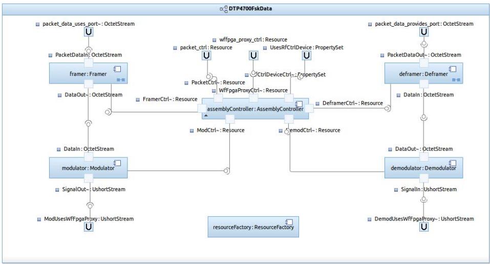
![**Title:** DTP4700FskData\n\n**Main Blocks:**\n*   **framer**: Framer\n*   **modulator**: Modulator\n*   **assemblyController**: AssemblyController\n*   **deframer**: Deframer\n*   **demodulator**: Demodulator\n*   **resourceFactory**: ResourceFactory\n\n**Connections and Labels:**\n\n*   **Left Side (Transmission Path):**\n    *   **packet_data_uses_port**: OctetStream connects to **framer**: Framer.\n    *   **framer**: Framer has an input labeled **PacketDataIn**: OctetStream and an output labeled **DataOut**: OctetStream.\n    *   **DataOut**: OctetStream connects to **modulator**: Modulator.\n    *   **modulator**: Modulator has an input labeled **DataIn**: OctetStream and an output labeled **SignalOut**: UshortStream.\n    *   **SignalOut**: UshortStream connects to **ModUsesWfPpgaProxy**: UshortStream.\n\n*   **Right Side (Reception Path):**\n    *   **packet_data_provides_port**: OctetStream connects to **deframer**: Deframer.\n    *   **deframer**: Deframer has an internal label **PacketDataOut**: OctetStream and an input labeled **DataIn**: OctetStream.\n    *   **DataIn**: OctetStream connects from **demodulator**: Demodulator.\n    *   **demodulator**: Demodulator has an output labeled **DataOut**: OctetStream and an input labeled **SignalIn**: UshortStream.\n    *   **SignalIn**: UshortStream connects from **DemodUsesWfPpgaProxy**: UshortStream.\n\n*   **Central Control (assemblyController):**\n    *   **assemblyController**: AssemblyController connects to **FramerCtrl**: Resource and **DeframerCtrl**: Resource.\n    *   **assemblyController**: AssemblyController connects to **ModCtrl**: Resource and **DemodCtrl**: Resource.\n    *   **assemblyController**: AssemblyController is associated with **packet_ctrl**: Resource, **UsesRfCtrlDevice**: PropertySet, **CtrlDeviceCtrl**: PropertySet, **PacketCtrl**: Resource, and **WfPpgaProxyCtrl**: Resource.\n\n*   **Bottom:**\n    *   **resourceFactory**: ResourceFactory is located at the bottom center.](.spectra-dtp4700-userguide/8e924778907bb4111ff1643fb3b3f5cde68bc92c26eadb2eb200d9806890cf04.jpg)

Figure 17 DTP4700FskData Application Assembly

framer: model element contained within the DTP4700FskData assembly represents an instance of the Framer component definition in Spectra CX. The framer accepts data from an instance of the PacketService component running on the platform. The data payload is encoded using a frame delimitation scheme based on HDLC1. The resulting signal is provided as input to the modulator.

deframer: model element contained within the DTP4700FskData assembly represents an instance of the Deframer component definition in Spectra CX. The deframer accepts a digital signal from an instance of the WfFpgaProxy component running on the platform. The input signal is decoded using a frame delimitation scheme based on HDLC. The resulting data is provided as input to an instance of the PacketService component running on the platform.

modulator: model element contained within the DTP4700FskData assembly represents an instance of the Modulator component definition in Spectra CX. The component modulates the input signal received from the framer using Frequency Shift Keying (FSK) scheme. The modulator produces a digital I&Q baseband signal at 64 kilo-samples/sec for the radio link by providing the signal as input to an instance of the WfFpgaProxy component running on the platform.

demodulator: model element contained within the DTP4700FskData assembly represents an instance of the Demodulator component definition in Spectra CX. The component demodulates the digital I&Q baseband signal received from the radio link via an instance of the WfFpgaProxy component running on the platform. The demodulated signal is provided as input to the deframer.

assemblyController: model element represents an instance of the AssemblyController component definition. The control parameters supporting the data waveform are set on the RfCtrlDevice by the assemblyController programmatically on application start-up.

resourceFactory: model element contained within the DTP4700FskData assembly represents an instance of the ResourceFactory component definition. The resourceFactory is responsible for creating instances of components of type Modulator and Demodulator.

# CHAPTER

# 6 Connectivity and Communication

When forward engineering applications for the DTP4700 platform using Spectra CX, the connections between components are exclusively defined at the SCA modelling level.

The SCA definition includes all port connections between application components and those which connect waveform with platform. The communication model adopted for the DTP4700 platform ensures that components deployed onto the GPP and/or the DSP cores of the OMAP processing unit over such connections is facilitated using CORBA at the middleware level1. The actual transport used, however, is adaptable, and is typically based on the physical interconnect fabric available. In the DTP4700, the inter-device transport used for connections made between the GPP and DSP OMAP cores is based on the Message Queue Transport (MQT) from Texas Instruments. This is also used for intra-DSP connections.

# 6.1 Spectra CX Build Configurations for the DTP4700

The Spectra CX system uses a ‘build configuration’ to configure content and control elements of the code generation procedure applied to individual components. Principally, the build configuration is used to assign the required implementation language for a given component; however, additional features may be built-in that affect the capabilities of the generated code. Typically, therefore, the selection of a build configuration may determine the level of debugging support and/or enable the use of a particular message transport at the middleware level.

A series of build configurations have been packaged with Spectra CX to reflect the platform-specific capabilities of the DTP4700 system and the underlying Thunder hardware. Table 5 provides a summary of the build configurations provided.

Table 5 Spectra CX Build Configurations

<table><tr><td>Build Configuration</td><td>Target OS/Architecture</td><td>Description</td></tr><tr><td>eorb-dspbios-cl6x::eorb20-dspbios-cl6x-linux-c-dtp4700-build</td><td>DSPBios/C6416</td><td>C based build configuration including MSGQIOP transport only</td></tr><tr><td>eorb-dspbios-cl6x::eorb20-dspbios-cl6x-linux-c-dtp4700+ probes-build</td><td>DSPBios/C6416</td><td>C based build configuration including MSGQIOP transport and support for Spectra DTP4700 Probe Toolbox</td></tr><tr><td>eorb20-linux-gcc-arm::eorb20-linux-gcc-arm-dtp4700+ msgqiop-build</td><td>TILinux/ARM</td><td>C++ based build configuration including MSGQIOP and IIOP transports</td></tr><tr><td>eorb20-linux-gcc-arm::eorb20-linux-gcc-arm-dtp4700+msgqiop+ probes-build</td><td>TILinux/ARM</td><td>C++ based build configuration including MSGQIOP and IIOP transports as well as support for Spectra DTP4700 Probe Toolbox</td></tr><tr><td>eorb20-linux-gcc-arm::eorb20-linux-gcc-arm-dtp4700-build</td><td>TILinux/ARM</td><td>C++ based build configuration including IIOP transport only</td></tr><tr><td>eorb20-linux-gcc-x86::eorb20-linux-gcc-x86-build</td><td>Linux/x86</td><td>C++ based build configuration including IIOP transport only</td></tr><tr><td>eorb20-linux-gcc-x86-c::eorb20-linux-gcc-x86-c-build</td><td>Linux/x86</td><td>C based build configuration including IIOP transport only</td></tr></table>

Debug versions of the build configurations listed in Table 5 are also provided.

# 6.2 Modelling Platform Specific Elements

Inter-device communication between the GPP and DSP on the DTP4700 platform is facilitated at the modelling level by assigning the associated component implementation model element in Spectra CX with the appropriate build configuration (see Table 5 above and Figure 18 on page 51).

The build configuration affects code generation for the component to which it is assigned, including the installation of the required transport to be used for the connections made at runtime between component ports. All data transports are integrated at the middleware level using the Extensible Transport Framework (ETF)

of the Spectra ORB, however, this procedure is entirely transparent to the end-user. In the case of connectivity with the DSP the native DSP/BIOS Message Queue transport mechanism from Texas Instruments is used.
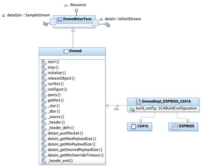
![**Blocks:**\n\n*   **DemodInterface** (Top block)\n    *   Associated text: 'dataOut--: SampleStream' (left), 'dataIn: UshortStream' (right), 'Resource' (top).\n*   **Demod** (Middle-left block)\n    *   List of methods/attributes:\n        *   start()\n        *   stop()\n        *   initialize()\n        *   releaseObject()\n        *   runTest()\n        *   configure()\n        *   query()\n        *   getPort()\n        *   _ctor()\n        *   _dtor()\n        *   _source()\n        *   _header\n        *   _header_defn()\n        *   dataIn_pushPacket()\n        *   dataIn_getMaxPayloadSize()\n        *   dataIn_getMinPayloadSize()\n        *   dataIn_getDesiredPayloadSize()\n        *   dataIn_getMinOverrideTimeout()\n        *   _header_end()\n*   **DemodImpl_DSPBIOS_C6416** (Middle-right block)\n    *   Associated text: 'build_config: SCABuildConfiguration'\n*   **C6416** (Bottom-right block)\n*   **DSPBIOS** (Bottom-right block)\n\n**Connections:**\n\n*   A solid arrow points upward from the **Demod** block to the **DemodInterface** block.\n*   A dashed arrow points left from the **DemodImpl_DSPBIOS_C6416** block toward the **Demod** block.\n*   A dashed arrow points downward from the **DemodImpl_DSPBIOS_C6416** block to the **C6416** block.\n*   A dashed arrow points downward from the **DemodImpl_DSPBIOS_C6416** block to the **DSPBIOS** block.](.spectra-dtp4700-userguide/3d71cfcb46d99984231f1bc58762d1dbc4ca575d48f2803876f194e9927fc596.jpg)

Figure 18 Definition of Demod Component

# 6.3 Connecting Waveform with Platform

There are currently three SCA platform services provided with this version of the DTP4700: one for audio, one for making connections to the network interface, and one for the radio link (RF/Transceiver sub-system). These are provided by the AudioPortDevice, the PacketService, and by a combination of the RfCtrlDevice and WfFpgaProxy components supporting the radio link respectively. The latter provides an SCA abstraction of the low-level Wf FPGA device driver libraries allowing configuration and control of the Thunder RF/Transceiver sub-system hardware, and a connection for exchanging sampled complex baseband signal data for the RF transmit and receive paths.

This section of the User Guide provides guidance for modelling connections between application components and DTP4700 platform components. In general waveform components (CF::Resource) connect to the platform by specifying uses device dependencies based on allocation properties defined by the DTP4700 platform. Table 6 shows the allocation properties defined by the various DTP4700 platform components and the value required to create a connection.

Table 6 DTP4700 Platform Allocation Properties

<table><tr><td>Device</td><td>Property Name</td><td>Required Value</td></tr><tr><td>AudioPortDevice</td><td>UsesAudioPortDeviceType</td><td>1</td></tr><tr><td>PacketService</td><td>UsesPacketServiceType</td><td>1</td></tr><tr><td>RfCtrlDevice</td><td>UsesRfCtrlDeviceType</td><td>1</td></tr><tr><td>WfFpgaProxy</td><td>UsesWfFpgaProxyType</td><td>1</td></tr></table>

The example provided in the next section demonstrates how to create a waveform component (CF::Resource) in Spectra CX with connections to transfer signal data to and from the RF/Transceiver sub-system of the Thunder system.

# 6.3.1 Connecting to the RF/Transceiver Sub-System

Step 1: Using Spectra CX, right-click in the Project Explorer view and choose New > SCA Model Project from the menu. Name the project Transceiver\_Connection, then click Next. Name the default SCA model Transceiver\_Connection, and then click Finish.

Step 2: The Rational model editor should open automatically for the new model. With the editor visible, switch to the Details tab and in the Model Libraries section click the Add button. Select JTRS Packet API from the Deployed Library drop-down list and click OK. Save the model.

Step 3: Expand the Transceiver\_Connection project in the Project Explorer view, right-click the Transceiver\_Connection model and choose Add CX > Component from the menu. Name the component Modem, ensuring that the component type is set to Resource, then click Finish.

Step 4: The diagram for the Modem component will open automatically. With the diagram visible, and with the Port object under SCA Application drawer of the Palette view selected, left-click on the ModemInterface model element in the diagram to attach a port to the Modem.

Step 5: Select the port element in the diagram and open the Properties view to display the model properties for the port. Ensure that the SCA tab in the Properties view is selected. In the Properties view, give the port the name dataOut, and set the Conjugation to Uses. Click the pencil icon in the Properties view to define the Porttype, and in the resulting dialog box type UshortStream in the Choose an element field. Select the UshortStream - Packet::Packet::Packet::UshortStream interface type from the resulting list of available interfaces, then click OK.

Step 6: Repeat Steps 4 and 5 to create another port, this time give the port the name dataIn, and set the Conjugation to Provides.

# This stage is illustrated in Figure 19.

![Spectra CX Modeling - Modem - Rational® Software Architect\nUbuntu\nB\nB\nI\nQuick Access\n100%\nSpectra CX Modeling\nProject Explorer\nLayers\nModem\nResource\nDataOut: UshortStream\nModemInterface\ndatain: UshortStream\nModem\nModemimpl\nModelConfiguration\n(CF_IDL)\n(IDL Primitives)\nOutline\nMake Target\nModem\nQueries\nModem\nModemInterface\nModemimpl\nResource\nStart()\nStop()\nInitialize()\nreleaseObject()\nrunTest()\nconfigure()\nquery()\ngetPort()\notor()\ndfor()\n_source()\n_header()\n_header_defm()\ndataln_pushPacket()\ndataln_getMaxPayloadSize()\ndataln_getMaxPayloadSize()\ndataln_getDevicePayloadSize()\ndataln_getMinOverrideTimeout()\n_header_end()\nModemimpl\nModemInterface\nModem\nModemInterface\nModem\nModemImpl\nModemImpl\nModemImpl\nProperties\nTasks\nConsole\nBookmarks\nSCA XML Problems\nSCA Connectors\n(Port) dataIn\nSCA\nName:\ndataIn\nConjugation:\nProvides\nUses\nKind:\nEntries: 0\nPorttype:\nPacket::Packet::Packet::UshortStream\nWritable Autosized](.spectra-dtp4700-userguide/3b6c3321cc4ccca0c778cc97f1c402fe878a0822d92466790d0992597d0eb27f.jpg)

Figure 19 Attaching a port to a component

Step 7: Right-click on the Transceiver\_Connection model in the Project Explorer view and select Add Diagram > CX Component Diagram from the menu. Name the diagram Transceiver\_Connection. With the diagram visible, and with the Application object under SCA Application drawer of the Palette view selected, left-click on the diagram canvas to create an application model element. Name the application Transceiver\_Connection.

Step 8: With the Transceiver\_Connection diagram containing the Transceiver\_Connection application model element visible, expand the Modem model folder in the Project Explorer view. Left-click on the on the Modem model element (structural realization) and drag the icon onto the diagram canvas to a location inside the bounding box of the Transceiver\_Connection application. This will include an instance of the Modem component definition into the Transceiver\_Connection application. A corresponding model element for the Transceiver\_Connection application will appear in the Project Explorer view under the Transceiver\_Connection model. This is illustrated in Figure 20.

![Spectra CX Modeling - Transceiver_Connection::Transceiver_Connection - Rational® Software Architect\nUbuntu 8 B I 100%\nQuick Access\nSpectra CX Modeling\nProject Explorer\nLayers\nTransceiver_Connection\nDataOut::UShortStream\nmodem:Modem\ndatain:UShortStream\nModemInterface\nModem\nModemImpl\nwFpgaProxy\nTransceiver_Connection\nTransceiver_Connection\nOutline\nMake Target\nTransceiver_Connection\nQueries\nTransceiver_Connection\nProperties\nTasks Console Bookmarks SCA XML Problems SCA Connectors\n(Component)Transceiver_Connection::Transceiver_Connection\nSCA Name: Transceiver_Connection\nID: DCE:7826C752-ffc4-46e1-918c-80e4f58884bd\nController: null\nDescription:\nVersion:\n(Component)Transceiver_Connection::Transceiver_Connection Writable Autosized](.spectra-dtp4700-userguide/e202a3553fb249ba7677dd1a6fa74db71dc4563c78454c8034792ee726e28465.jpg)

Figure 20 Defining an Application

Step 9: Open the diagram for the Modem component as shown in Figure 19. With the UsesDevice element under the SCA Application drawer of the Palette view selected, left-click on the Modem diagram to create an instance of a uses device relationship. Select the UsesDevice element in the diagram, and in the Properties view name the UsesDevice model element wfFpgaProxy.

Step 10:Ensure that the diagram for the Modem component is visible. With the UsesDevice Dependency element under the SCA Application drawer of the Palette view selected, draw a line connecting the structural realisation of the Modem to the wfFpgaProxy UsesDevice model element in the diagram. Select the UsesDevice Dependency element in the diagram, and in the Properties view name the UsesDevice Dependency model element usesWfFpgaProxy.

Step 11: Ensure that the diagram for the Modem component is visible. Expand the DTP4700 project in the Project Explorer view and navigate to the WfFpgaProxy component definition. Left-click on the UsesWfFpgaProxyType property model element and drag the icon onto the diagram canvas for the Modem. With the Property Dependency element under the SCA Application drawer of the Palette view selected, draw a line connecting the wfFpgaProxy UsesDevice to the UsesWfFpgaProxyType model element in the diagram. Select the Property Dependency element in the diagram, and in the Properties view enter the value ‘1’. This is shown in Figure 21.

![Based on the provided image, here is the accurate description of the flowchart/block diagram:\n\n**Labeled Blocks:**\n*   **ModemInterface**: Located at the top center. It contains a label 'Resource' above it, ports labeled 'dataOut: UshortStream' and 'dataIn: UshortStream', and a method label 'put'.\n*   **Modem**: Located below ModemInterface. It lists the following methods: `start()`, `stop()`, `initialize()`, `releaseObject()`, `runTest()`, `configure()`, `query()`, `getPort()`, `_ctor()`, `_dtr()`, `_source()`, `_header()`, `_header_defn()`, `detail_postPacket()`, `detail_getMaxPayloadSize()`, `detail_getMinPayloadSize()`, `detail_getDesiredPayloadSize()`, `detail_getMinOverideTimeout()`, `detail_header_end()`.\n*   **ModemImpl**: Located to the right.\n*   **wfFpgaProxy**: Located below ModemImpl.\n*   **UsesWfFpgaProxyType**: Located below wfFpgaProxy.\n*   **GXP**: Located below UsesWfFpgaProxyType.\n\n**Connections:**\n*   **Modem** to **ModemInterface**: A solid line with a hollow arrowhead points from the bottom of the **Modem** block up to the bottom of the **ModemInterface** block.\n*   **ModemImpl** to **Modem**: A dashed line with a hollow arrowhead points from the left side of the **ModemImpl** block to the right side of the **Modem** block.\n*   **wfFpgaProxy** to **ModemImpl**: A dashed line with an open arrowhead points from the **wfFpgaProxy** block upwards to the **ModemImpl** block. The text 'usesWfFpgaProxy' is displayed on this connection.\n*   **wfFpgaProxy** to **UsesWfFpgaProxyType**: A dashed line with an open arrowhead points from the **wfFpgaProxy** block downwards to the **UsesWfFpgaProxyType** block.\n*   **UsesWfFpgaProxyType** to **GXP**: A dashed line with an open arrowhead points from the **UsesWfFpgaProxyType** block downwards to the **GXP** block.](.spectra-dtp4700-userguide/b7dc83575e3b304608de9272b82869c5f2849633002008bf3a819928cb8d24cc.jpg)

Figure 21 Uses Device Dependency

Step 12:Ensure that the Transceiver\_Connection diagram containing the Transceiver\_Connection application model element is visible. With the Free Standing Port (FSP) Device Used By element under the SCA Application drawer of the Palette view selected, left-click within the bounding box of the Transceiver\_Connection Application to create an instance of a used by relationship for component ports included in the application.

Step 13:Select the Free Standing Port (FSP) Device Used By element in the diagram and then, in the Properties view, set the Free Standing Port (FSP) Device Used By element properties as follows:

```txt
Name: wffpga_rx
Findby Port Name: wffpga_proxy_uses_port. Note: the port name MUST match (string equivalent) the required port on the WfFpgaProxy component.
Part: modem -
Transceiver_Connection::Transceiver_Connection::modem
Uses Device: usesWfFpgaProxy -
Transceiver_Connection::Modem::usesWfFpgaProxy
Conjugation: Uses
Porttype: UshortStream - Packet::Packet::Packet:UshortStream
```

Step 14:With the Connector element under the SCA Application drawer of the Palette view selected, link the dataIn port to the wffpga\_rx FSP.

Step 15:Repeat steps 12 to 14 to model a wfpga\_tx connection to the WfFpgaProxy component to send data to the RF/Transceiver sub-system from the Modem’s dataOut port.

The Free Standing Port (FSP) Device Used By element should have the following properties:

```txt
Findby Port Name: wffpga_proxyProvides_port
Part: modem -
Transceiver_Connection::Transceiver_Connection::modem
Uses Device: usesWfFpgaProxy -
Transceiver_Connection::Modem::usesWfFpgaProxy
Conjugation: Provides
Porttype: UshortStream - Packet::Packet::Packet:UshortStream
```

![Based on the provided image, here is the description of the flowchart/block diagram:\n\n**Labeled Blocks:**\n*   **Transceiver_Connection**: This is the outer container block (blue header bar).\n*   **modem: Modem**: This is the central component block (blue rectangle) inside the container.\n\n**Connections and Labels:**\n*   **Left Side Connection**: A vertical line extends downward from the left side of the 'modem: Modem' block.\n    *   At the top of this line (near the block), the label is **'dataOut: UshortStream'**.\n    *   At the bottom of this line (near a small square symbol), the label is **'wfpga_tx: UshortStream'**.\n*   **Right Side Connection**: A vertical line extends downward from the right side of the 'modem: Modem' block.\n    *   At the top of this line (near the block), the label is **'dataIn: UshortStream'**.\n    *   At the bottom of this line (near a small square symbol), the label is **'wfpga_rx: UshortStream'**.](.spectra-dtp4700-userguide/875c27a8dfc3a5f46424eb432b3984851ab940f80213de87aa446627d3f5f2e2.jpg)

Figure 22 RF/Transceiver sub-system data link

# CHAPTER

# （20 DTP4700 Probe Toolbox

The DTP4700 LiveUSB system contains a full installation of the Spectra DTP4700 Probe Toolbox including the ProbeViz visualization software which is installed into IBM Rational Software Architect alongside Spectra CX.

i Documentation for the Probe Toolbox software can be found in the PrismTech menu under Spectra > Thunder > SDR Probe Toolbox User Manual / SDR Probe Toolbox API Documentation.

This section of the User Guide describes additional components specifically provided to support the DTP4700 system.

# 7.1 DSP Probe Support

The Probes API for DSP requires a GPP-based probe listener to be running before test and latency probes can be registered. The DTP4700 SCA platform includes the DSPProbeListenerService device which starts the required listeners during platform deployment and stops the listeners when the platform is shut down. This allows users of the DTP4700 system to add test and latency probes to a DSP-based component without having to perform any extra initialization on the GPP.

# 7.2 Spectra CX Build Configurations

Additional Spectra CX build configurations are provided for both the ARM and DSP processors. These build configurations can be used to generate a build environment pre-configured with the necessary compiler settings to support software probes. Table 7 lists the build configurations which include probe support.

Table 7 Spectra CX build configurations including probe support

<table><tr><td>Build Configuration</td><td>Target</td></tr><tr><td>eorb-dspbios-cl6x::eorb20-dspbios-cl6x-linux-c-dtp4700+probes-build</td><td>DSPBIOS/DSP</td></tr><tr><td>eorb20-linux-gcc-arm::eorb20-linux-gcc-arm-dtp4700+msgqiop+probes-build</td><td>TILinux/ARM</td></tr></table>

Debug versions of the build configurations listed in Table 7 are also provided.

The build configurations listed in Table 7 set a compiler define named DTP\_PROBES. Through the use of preprocessor directives this compiler define can be used to optionally add software probes into a component. The FM Waveform example uses this compiler define in this way so that probes are only registered by the components if one of the build configurations in Table 7 is used.

# 7.3 ProbeViz

The ProbeViz visualization tool included with the DTP4700 LiveUSB system can be accessed from within IBM Rational Software Architect. To access ProbeViz, open the ProbeViz perspective within RSA.

![| Frequency (fs/2) | Magnitude (dB) |\n| ---------------- | -------------- |\n| -1.00            | ~60            |\n| -0.75            | ~65            |\n| -0.50            | ~68            |\n| -0.25            | ~72            |\n| 0.00             | ~115           |\n| 0.25             | ~70            |\n| 0.50             | ~65            |\n| 0.75             | ~60            |\n| 1.00             | ~55            |](.spectra-dtp4700-userguide/bd190f579b04d6ebc8d27195b1716493d3c6c99e342c8c3f4ef17a658f23b7e7.jpg)

Figure 23 ProbeViz visualization tool

# 7.4 Example Waveform

The example FM Waveform included with the DTP4700 system is instrumented with test and latency probes. Data from these probes can be accessed via ProbeViz when the waveform is running.

![Based on the provided block diagram, here are the labeled blocks and their connections:\n\n**Labeled Blocks:**\n*   `speaker: SampleStream`\n*   `downsampler: Resampler = ResamplerInstance`\n*   `demod: Demod`\n*   `wffpga_rx~: UshortStream`\n*   `UsesRfCtrlDevice: PropertySet`\n*   `assemblyController: AssemblyController`\n*   `upsampler: Resampler = ResamplerInstance`\n*   `line_in~: SampleStream`\n*   `mod: Mod`\n*   `wffpga_tx~: UshortStream`\n*   `resourceFactory: ResourceFactory`\n\n**Connections:**\n\n**Data Flow (Left/Receive Path):**\n*   `speaker: SampleStream` connects to `dataOut~: SampleStream`.\n*   `dataOut~: SampleStream` connects to `downsampler: Resampler = ResamplerInstance`.\n*   `downsampler: Resampler = ResamplerInstance` connects to `dataIn~: SampleStream`.\n*   `dataIn~: SampleStream` connects to `dataOut~: SampleStream`.\n*   `dataOut~: SampleStream` connects to `demod: Demod`.\n*   `demod: Demod` connects to `dataIn~: UshortStream`.\n*   `dataIn~: UshortStream` connects to `wffpga_rx~: UshortStream`.\n\n**Data Flow (Right/Transmit Path):**\n*   `line_in~: SampleStream` connects to `dataIn~: SampleStream`.\n*   `dataIn~: SampleStream` connects to `upsampler: Resampler = ResamplerInstance`.\n*   `upsampler: Resampler = ResamplerInstance` connects to `dataOut~: SampleStream`.\n*   `dataOut~: SampleStream` connects to `dataIn~: SampleStream`.\n*   `dataIn~: SampleStream` connects to `mod: Mod`.\n*   `mod: Mod` connects to `dataOut~: UshortStream`.\n*   `dataOut~: UshortStream` connects to `wffpga_tx~: UshortStream`.\n\n**Control and Resource Connections:**\n*   `assemblyController: AssemblyController` connects to `UsesRfCtrlDevice: PropertySet` via `RfCtrlDeviceCtrl~: PropertySet`.\n*   `assemblyController: AssemblyController` connects to `downsampler: Resampler = ResamplerInstance` via `downsamplerCtrl~: Resource`.\n*   `assemblyController: AssemblyController` connects to `demod: Demod` via `demodCtrl~: Resource`.\n*   `assemblyController: AssemblyController` connects to `upsampler: Resampler = ResamplerInstance` via `upsamplerCtrl~: Resource`.\n*   `assemblyController: AssemblyController` connects to `mod: Mod` via `modCtrl~: Resource`.\n*   `assemblyController: AssemblyController` connects to `wffpga_proxy_ctrl: Resource` via `WffpgaProxyCtrl~: Resource`.\n*   `assemblyController: AssemblyController` connects to `audio_ctrl: Resource` via `audioCtrl~: Resource`.](.spectra-dtp4700-userguide/c4e43c595c606d9768ffcaebc987ae9bf30fda7040518ddf6042c2aa6539f272.jpg)

Figure 24 DTP4700Fm Application Assembly model

Table 8 below lists the test probes and Table 9 lists the latency probes that are registered by the FM waveform example. All the test probes registered by the FM waveform are extraction probes.

Table 8 Test probes registered by the FM waveform

<table><tr><td>Name</td><td>Data Type</td><td>Data Source</td></tr><tr><td>upsampler_test_in</td><td>Signed 16 bit Integer</td><td>GPP</td></tr><tr><td>upsampler_test_out</td><td>Signed 16 bit Integer</td><td>GPP</td></tr><tr><td>mod_test_in</td><td>Signed 16 bit Integer</td><td>DSP</td></tr><tr><td>mod_test_out</td><td>Complex Signed 16 bit Integer (I &amp; Q)</td><td>DSP</td></tr><tr><td>demod_test_in</td><td>Complex Signed 16 bit Integer (I &amp; Q)</td><td>DSP</td></tr><tr><td>demod_test_out</td><td>Signed 16 bit Integer</td><td>DSP</td></tr><tr><td>downsampler_test_in</td><td>Signed 16 bit Integer</td><td>GPP</td></tr><tr><td>downsampler_test_out</td><td>Signed 16 bit Integer</td><td>GPP</td></tr></table>

Table 9 Latency probes registered by the FM waveform

<table><tr><td>Group Number</td><td>Probe Number</td><td>Location</td></tr><tr><td rowspan="4">1(Tx)</td><td>1</td><td>upsampler dataIn</td></tr><tr><td>2</td><td>upsampler dataOut</td></tr><tr><td>3</td><td>mod dataIn</td></tr><tr><td>4</td><td>mod dataOut</td></tr><tr><td rowspan="4">2(Rx)</td><td>1</td><td>demod dataIn</td></tr><tr><td>2</td><td>demod dataOut</td></tr><tr><td>3</td><td>downsampler dataIn</td></tr><tr><td>4</td><td>downsampler dataOut</td></tr></table>

# 7.4.1 Probe Registration

# 7.4.1.1 GPP Probe Registration

The probes API on the GPP allows for individual probes to be registered independently, the only restriction being that each probe name (in the case of test probes) or number (in the case of latency probes) is unique.

In the example FM waveform the upsampler and downsampler component instances register probes. The upsampler and downsampler are instances of the R e s a m p l e r c o m p o n e n t c o n f i g u r e d d i ff e r e n t l y t o c a r r y o u t upsampling/downsampling respectively. Probes are registered in the Resampler component’s constructor based on the name of the component instance. Probes are unregistered in the Resampler component’s destructor.

# 7.4.1.2 DSP Probe Registration

The probes API on the DSP requires that for each type of probe all instances are registered at the same time. This means that while test and latency probe types can be registered separately, all test probes must be registered at the same time and all latency probes must also be registered at the same time.

The example FM waveform deploys two components, Mod and Demod, to the DSP. As the DSP can only run a single binary at any one time these components are deployed via the ResourceFactory component. As probes must be registered at the s a m e t i m e , p r o b e r e g i s t r a t i o n o c c u r s i n t h e i n i t f u n c t i o n o f t h e ResourceFactory component. Probes are unregistered in the fini function of the ResourceFactory component.

# 7.4.2 Latency Probes

The example FM waveform contains two groups of latency probes. Group 1 monitors latency through the Tx pipeline and group 2 monitors latency through the Rx pipeline. Latency probes within a group must be called in sequence. As each part of the Tx and Rx pipelines can be active simultaneously latency is measured every 50 packets to ensure that each probe is called in sequence.

# 8

# SCA Waveform Tutorial

This chapter uses the supplied FM waveform to illustrate the general procedures required to:

• generate, build, and compile component assemblies using a Spectra CX model,
• prepare a domain profile on the target filesystem (SD card) in readiness for running an SCA application on DTP4700
• connect the Spectra CX Monitor running on the host to the DTP4700 SCA platform on the target to control the life cycle of waveform applications

The DTP4700 is delivered with an SD card already prepared, including the demo waveforms. To run the supplied FM waveform example directly and bypass Spectra CX modelling and code generation steps, please see Section 8.2.10, Running the FM Waveform, on page 88.

# 8.1 The FM Waveform Model

The Spectra CX model for the DTP4700Fm application assembly, as described in Section 5.2 on page 41, will be used as the basis for this tutorial. The components used in the application assembly realize ports and properties designed to interconnect components to form the audio data path and to control the operation of the audio waveform.

Table 10 Component Port Properties

<table><tr><td>Component</td><td>Ports</td><td>Properties</td></tr><tr><td rowspan="2">Mod</td><td>dataIn: Exposes the SampleStream interface for incoming UshortStream data and control</td><td rowspan="2">gain: A CORBA::short to hold the modulator gain.The gain value is multiplied to each modulator complex I&amp;Q output pair</td></tr><tr><td>dataOut: Sends interleaved I&amp;Q data via the UshortStream interface</td></tr></table>

Table 10 Component Port Properties

<table><tr><td>Component</td><td>Ports</td><td>Properties</td></tr><tr><td rowspan="2">Demod</td><td>dataIn: Exposes the UshortStream interface for incoming interleaved I&amp;Q data and control</td><td rowspan="2">No configurable properties</td></tr><tr><td>dataOut: Sends sample data via the SampleStream interface</td></tr><tr><td rowspan="4">Resampler</td><td>dataIn: Exposes the SampleStream interface for incoming UshortStream data and control</td><td>numerator: A CORBA::short to hold the FIR filter numerator value.The numerator value is used in rate conversion such that output rate = input rate (numerator/denominator)</td></tr><tr><td rowspan="3">dataOut: Sends filtered data via the SampleStream interface</td><td>denominator: A CORBA::short to hold the FIR filter denominator value.The denominator value is used in rate conversion such that output rate = input rate (numerator/denominator)</td></tr><tr><td>filterGainAdj: A CORBA::short to hold the gain adjust for the FIR filter1</td></tr><tr><td>FilterCoeffs: A sequence of CORBA::short values to hold the fixed-point filter coefficients for the FIR filter</td></tr></table>

1. The filterGainAdj property on the Resampler is set with a default gain at the output of the filter of -32768 to adjust the dynamic range. The gain adjustment is applied in addition to the default gain. A filterGainAdj of 0 would leave the default gain unchanged.
Each filter output sample is shifted by N bits, where N > 0, the shift is to the left; where N &lt; 0, the shift is to the right, and N is given by:
filterGainAdj &gt; 0: round( log base 2( filterGainAdj ) ) – 15 or
filterGainAdj &lt; 0: round( -log base 2( -filterGainAdj ) ) – 15

# 8.2 The FM Tutorial Step-by-step

# 8.2.1 Starting Spectra CX

For convenience a link is provided under the PrismTech menu under Spectra &gt; DTP4700 > Workspaces > Spectra CX (DTP4700 workspace) on the host development system desktop that can be used to open a pre-existing Spectra CX workspace containing all the supplied model projects.

If starting Spectra CX using the above link, please continue this tutorial from Section 8.2.4, Generating DTP4700 Platform Artefacts, on page 73.

Alternatively to run Spectra CX creating a new workspace, choose IBM Software Delivery Platform > IBM Rational Software Architect 9.1 from the PrismTech menu, then continue this tutorial from Section 8.2.2, Choosing a Workspace, below.

# 8.2.2 Choosing a Workspace

When you start Spectra CX a dialog appears for you to choose where to locate your workspace. A workspace is a folder where the projects that you create will be stored. If you do not specify a workspace, a default workspace will be created for you.

Click OK when you have decided on your workspace location.
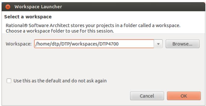
![Workspace Launcher\nSelect a workspace\nRational® Software Architect stores your projects in a folder called a workspace.\nChoose a workspace folder to use for this session.\nWorkspace: /home/dtp/DTP/workspaces/DTP4700\nBrowse...\nUse this as the default and do not ask again\nCancel	OK](.spectra-dtp4700-userguide/6ca6c0f761ddb3cefbeab5a309704af3f5af478fce34a7a6b22e01d08c8ce35d.jpg)

Figure 25 Select or create a workspace

The first time you open Spectra CX or create a new workspace, you will see a ‘Welcome’ screen.

Close the Welcome screen by clicking X on the tab or by clicking the Workbench icon (circled in Figure 26 below).
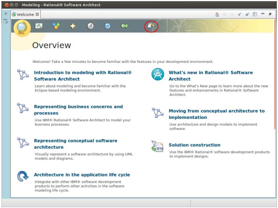
![Modeling - Rational® Software Architect\nOverview\nWelcome! Take a few minutes to become familiar with the features in your development environment.\nIntroduction to modeling with Rational® Software Architect\nLearn about modeling and become familiar with the Eclipse-based modeling environment.\nWhat's new in Rational® Software Architect\nGo to the What's New page to learn more about the new features and enhancements in Rational® Software Architect.\nRepresenting business concerns and processes\nUse IBM® Rational® Software Architect to model your business processes.\nMoving from conceptual architecture to implementation\nUse architecture and design models to implement software.\nRepresenting conceptual software architecture\nVisually represent a software architecture by using UML models and diagrams.\nSolution construction\nUse the IBM® Rational® software development products to implement designs.\nArchitecture in the application life cycle\nIntegrate with other IBM® software development products to perform other activities in the software modeling life cycle.](.spectra-dtp4700-userguide/ec44cea6711d30dab66051c657fbb2758836cb3e7fec63555c2f710078b7851c.jpg)

Figure 26 The ‘Welcome’ screen

The illustration overleaf (Figure 27) shows the default Workbench layout before any projects have been created.
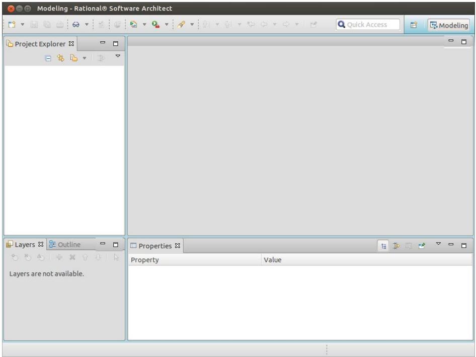
![Modeling - Rational® Software Architect\nQuick Access\nProject Explorer\nLayers Outline\nLayers are not available.\nProperties\nProperty Value](.spectra-dtp4700-userguide/b9aa28d6b0a62156291d426e215e2454e2d62a05764c3475f618083528fa84d9.jpg)

Figure 27 Default Workbench showing empty workspace

If you already have projects under development in Spectra CX then those projects are displayed in the Project Explorer pane. If, however, this is your first project, then the Project Explorer will show no projects in your workspace.

To w o r k w i t h D T P 4 7 0 0 m o d e l s , t h e t o o l m u s t b e s w i t c h e d t o t h e Spectra CX Modeling perspective.

F i g u re 2 8 , F i g u re 2 9 a n d F ig u re 3 0 s h o w h o w t o s w i t c h i n t o t h e Spectra CX Modeling perspective.
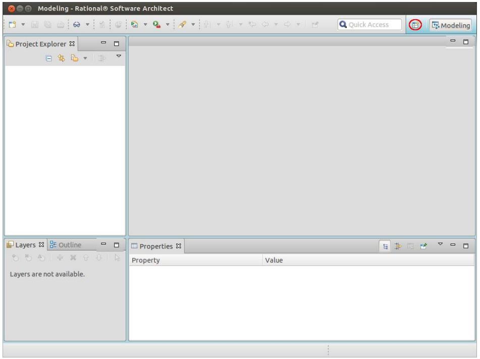
![Modeling - Rational® Software Architect\nQuick Access\nProject Explorer\nProject\nLayers\nOutline\nLayers are not available.\nProperties\nProperty	Value\n...](.spectra-dtp4700-userguide/dfc68d8dc67f5728666570aceeee36616780aca4cce762bd69a76099b324b984.jpg)

Figure 28 Click the Open Perspective button (circled)
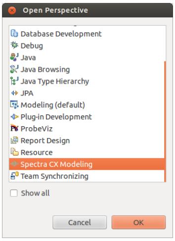
![Open Perspective\nDatabase Development\nDebug\nJava\nJava Browsing\nJava Type Hierarchy\nJPA\nModeling (default)\nPlug-in Development\nProbeViz\nReport Design\nResource\nSpectra CX Modeling\nTeam Synchronizing\nShow all\nCancel	OK](.spectra-dtp4700-userguide/8c90e6ceb54bf2b25323dcfc88c82804fb433f87721f244b691c15f49ce5582b.jpg)

Figure 29 Open the Spectra CX Modeling perspective
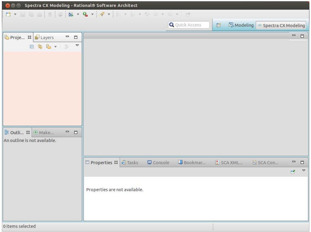
![Spectra CX Modeling - Rational® Software Architect\nQuick Access\nModeling\nSpectra CX Modeling\nProje...\nLayers\nOutli...\nMake...\nAn outline is not available.\nProperties\nTasks Console Bookmar... SCA XML... SCA Con...\nProperties are not available.\n0 items selected](.spectra-dtp4700-userguide/ecedefe8c59cf2767745359fe044d564e6db8c7fa5b86740d58a596315a28a8b.jpg)

Figure 30 The Spectra CX Modeling environment ready to start

# 8.2.3 Importing the DTP4700 Tutorial Packages

To import the DTP4700 tutorial packages into the workspace, perform the following steps.

Step 1: On the menu bar, choose File > Import; the dialog shown in Figure 31 will appear.
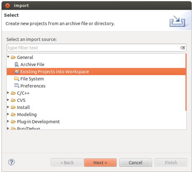
![Import\nSelect\nCreate new projects from an archive file or directory.\nSelect an import source:\ntype filter text\nGeneral\nArchive File\nExisting Projects into Workspace\nFile System\nPreferences\nC/C++\nCVS\nInstall\nModeling\nPlug-in Development\nRun/Debug\n( Back	Next )	Cancel	Finish](.spectra-dtp4700-userguide/8dbd51821df06f2f7d7069fbb31c1c8ce225f868e827e4051e23e9419c6207c8.jpg)

Figure 31 The Import Wizard

Step 2: Select Existing Projects into Workspace and click Next.

Step 3: Click the radio button for Select archive file and click the Browse button.

Step 4: Locate and select the zip file that contains the DTP4700 projects (projects are stored in /opt/dtp/models.zip).

i The models.zip archive contains five model projects:

- DTP4700: the DTP4700 SCA platform model.
- DTP4700Fm: the analog FM audio waveform used in this tutorial.
- DTP4700FskData: the data waveform which uses FSK modulation.
- DTP4700FskVoice: the digital audio waveform which uses CVSD encoding and FSK modulation.
- x86: additional platform nodes that can be used to deploy application components to the host development system.

Step 5: Click OK to use the selected archive.

Step 6: Click Finish to complete the import operation.

Step 7: The DTP4700 Platform and Tutorial FM waveform now appear in the Project Explorer pane.
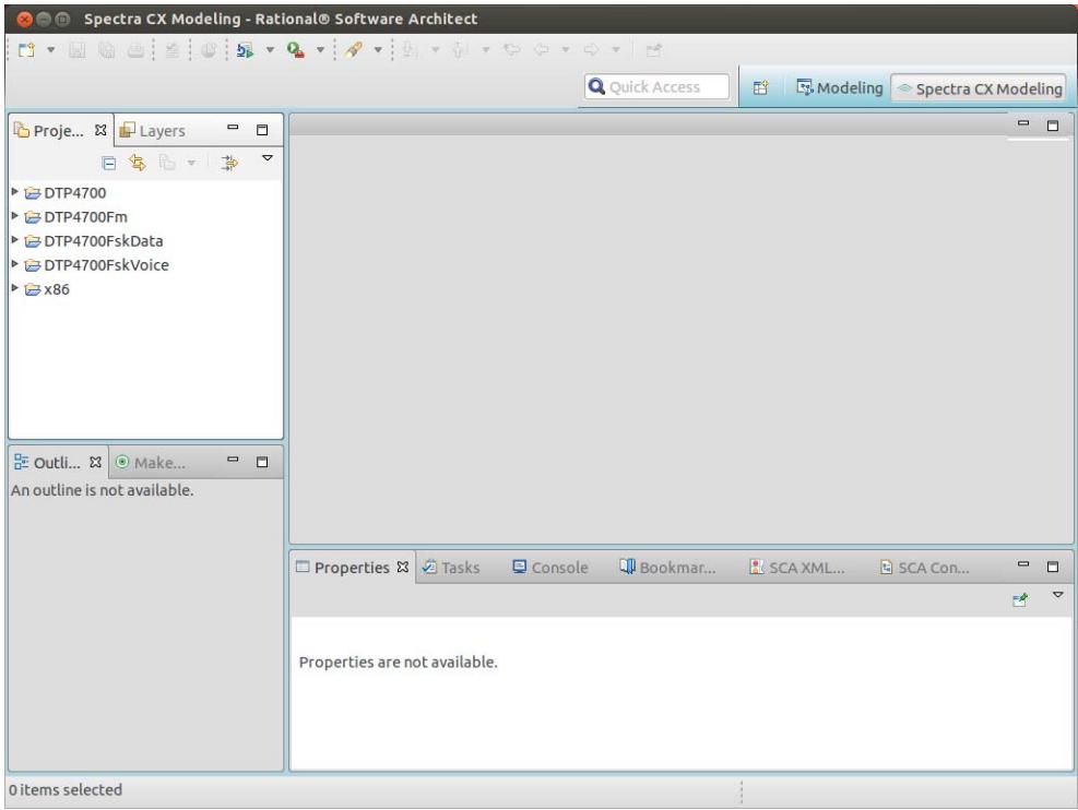
![Spectra CX Modeling - Rational® Software Architect\nQuick Access\nModeling\nSpectra CX Modeling\nProje...\nLayers\nDTP4700\nDTP4700Fm\nDTP4700FskData\nDTP4700FskVoice\nx86\nOutli...\nMake...\nAn outline is not available.\nProperties\nTasks Console Bookmar... SCA XML... SCA Con...\nProperties are not available.\n0 items selected](.spectra-dtp4700-userguide/1d2de6584f170ce103a23a4c3f09969b687234e758b3d553e64adeb57f916919.jpg)

Figure 32 Project Explorer showing imported projects

# 8.2.4 Generating DTP4700 Platform Artefacts

This section describes how to generate the domain profile and code for the DTP4700 platform.

Step 1: In the Project Explorer, expand the DTP4700 project, navigate to Models > DTP4700 > DTP4700, and double-click the DTP4700 diagram element in the tree.
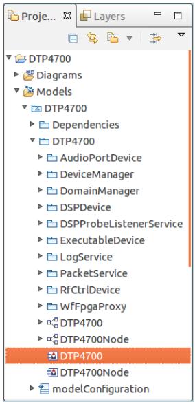
![DTP4700\nDiagrams\nModels\nDTP4700\nDependencies\nDTP4700\nAudioPortDevice\nDeviceManager\nDomainManager\nDSPDevice\nDSPProbeListenerService\nExecutableDevice\nLogService\nPacketService\nRfCtrlDevice\nWfFpgaProxy\nDTP4700\nDTP4700Node\nDTP4700\nDTP4700Node\nmodelConfiguration](.spectra-dtp4700-userguide/ab6fb3282aedd85c5466e4fbc33eb3ba4757c12514e97bf75295700a20361815.jpg)

Figure 33 DTP4700 diagram element selected in Project Explorer

This will display the diagram showing the platform model element containing an instance of the DTP4700Node named dtp4700Node. This is shown in Figure 34.
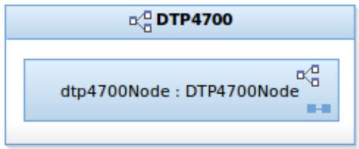
![DTP4700\ndtp4700Node : DTP4700Node](.spectra-dtp4700-userguide/cfe5df9924fde31ed21a624cd59346ddfeb54fbc0759d19184ebc733665aaba3.jpg)

Figure 34 The DTP4700 Platform Model Element

Step 2: Double-click the DTP4700Node diagram element in the tree. This will display the diagram showing the DTP4700Node and the component instances contained within it, as shown in Figure 35.
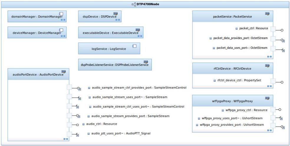
![This diagram depicts a system architecture block labeled **DTP4700Node**. It contains several distinct component blocks, some of which have detailed internal port listings.\n\n**Component Blocks:**\n*   `domainManager : DomainManager`\n*   `deviceManager : DeviceManager`\n*   `dspDevice : DSPDevice`\n*   `executableDevice : ExecutableDevice`\n*   `logService : LogService`\n*   `dspProbeListenerService : DSPProbeListenerService`\n\n**Detailed Blocks and Connections:**\n\n**1. `audioPortDevice : AudioPortDevice`** (Located on the bottom left)\n*   `audio_sample_stream_ctrl_provides_port : SampleStreamControl`\n*   `audio_sample_stream_uses_port~ : SampleStream`\n*   `audio_sample_stream_ctrl_uses_port~ : SampleStreamControl`\n*   `audio_sample_stream_provides_port : SampleStream`\n*   `audio_ctrl : Resource`\n*   `audio_ptt_uses_port~ : AudioPTT_Signal`\n\n**2. `packetService : PacketService`** (Located on the top right)\n*   `packet_ctrl : Resource`\n*   `packet_data_provides_port : OctetStream`\n*   `packet_data_uses_port~ : OctetStream`\n\n**3. `rfCtrlDevice : RfCtrlDevice`** (Located in the middle right)\n*   `rfctrl_device_ctrl : PropertySet`\n\n**4. `wlfpgaProxy : WfFpgaProxy`** (Located on the bottom right)\n*   `wlfpga_proxy_ctrl : Resource`\n*   `wlfpga_proxy_uses_port~ : UshortStream`\n*   `wlfpga_proxy_provides_port : UshortStream`](.spectra-dtp4700-userguide/70e9ab2a16b4b665035423f902eabd0f379dc762634d41331163bd4382ff6b53.jpg)

Figure 35 Components in the DTP4700Node

# 8.2.4.1 Generating DTP4700 SCA Descriptors

This section describes how to generate the XML domain profile for the DTP4700 platform.

Step 1: In the DTP4700 diagram, right-click on DTP4700 platform to open its context menu, then choose Generate > Descriptor(s).
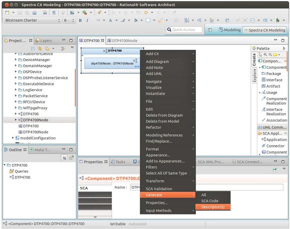
![Spectra CX Modeling - DTP4700::DTP4700::DTP4700 - Rational® Software Architect\nBitstream Charter 8 B I → A Quick Access Modeling Spectra CX Modeling\nProject ... Layers DTP4700 DTP4700Node\nAdd CX\nAdd Diagram\nAdd Note\nAdd UML\nNavigate\nVisualize\nInstantiate\nFile\nEdit\nDelete from Diagram\nDelete from Model\nRefactor\nModeling References\nFind/Replace...\nFormat\nAppearance...\nAdd to Appearances...\nFilters\nSelect All Of Same Type\nTransform\nSCA Validation\nGenerate All\nProperties... SCA Code\nInput Methods Descriptor(s)\nAudioPortDevice\nDeviceManager\nDomainManager\nDSPDevice\nDSPProbeListenerService\nExecutableDevice\nLogService\nPacketService\nRfCtrlDevice\nWfFpgaProxy\nDTP4700\nDTP4700Node\nDTP4700\nDTP4700Node\nmodelConfiguration\nOutline Make T...\nDTP4700\nQueries\nDTP4700\nProperties Tasks SCA XML Pro... SCA Connect...\n(Component) DTP4700::DTP4700\nSCA Name: DTP4700\nSCA Validation\nGenerate All\nProperties... SCA Code\nInput Methods Descriptor(s)\n(Component) DTP4700::DTP4700::DTP4700 Writable Autosized](.spectra-dtp4700-userguide/366d68900c3acdd3dfd96f2159be410d22f47053d1d1a664f277d297056fd356.jpg)

Figure 36 Generating SCA Descriptors

When the platform descriptors have been generated, the console will show validation status, errors, and warnings.
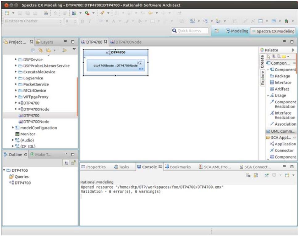
![Spectra CX Modeling - DTP4700::DTP4700::DTP4700 - Rational® Software Architect\nBliststream Charter\nQuick Access\nModeling\nSpectra CX Modeling\nProject ...\nLayers\nDSPDevice\nDSPProbeListenerService\nExecutableDevice\nLogService\nPacketService\nRFCtrlDevice\nWffpgaProxy\nDTP4700\nDTP4700Node\nDTP4700\nDTP4700Node\nmodelConfiguration\nMonitor\n(Audio)\n(CF IDL)\nOutline\nMake T...\nDTP4700\nQueries\nDTP4700\nDTP4700\nDTP4700\nDTP4700\ndtp4700Node : DTP4700Node\nPalette\nCompon...\nComponent\nPackage\nInterface\nArtifact\nUsage\nComponent Realization\nInterface Realization\nAssociation\nUML Comm...\nSCA Appl...\nApplication\nConnector\nComponent\nProperties Tasks Console Bookmarks SCA XML Pro... SCA Connect...\nRational Modeling\nOpened resource '/home/dtp/DTP/workspaces/foo/DTP4700/DTP4700.emx'\nValidation - 0 error(s), 0 warning(s)](.spectra-dtp4700-userguide/fc0f605fc41e6da9c8031cc3f651a8ada298281ff3eeca42810123f64d3f93dc.jpg)

Figure 37 After generating Platform Descriptors

In Figure 37 the Console tab shows the results of the Model Validation Procedure.

# 8.2.4.2 Generating DTP4700 SCA Source Code

This section describes how to generate source code for the DTP4700 platform.

Step 1: On the DTP4700 diagram, right-click the DTP4700 platform component, then choose Generate > SCA Code from the context menu.
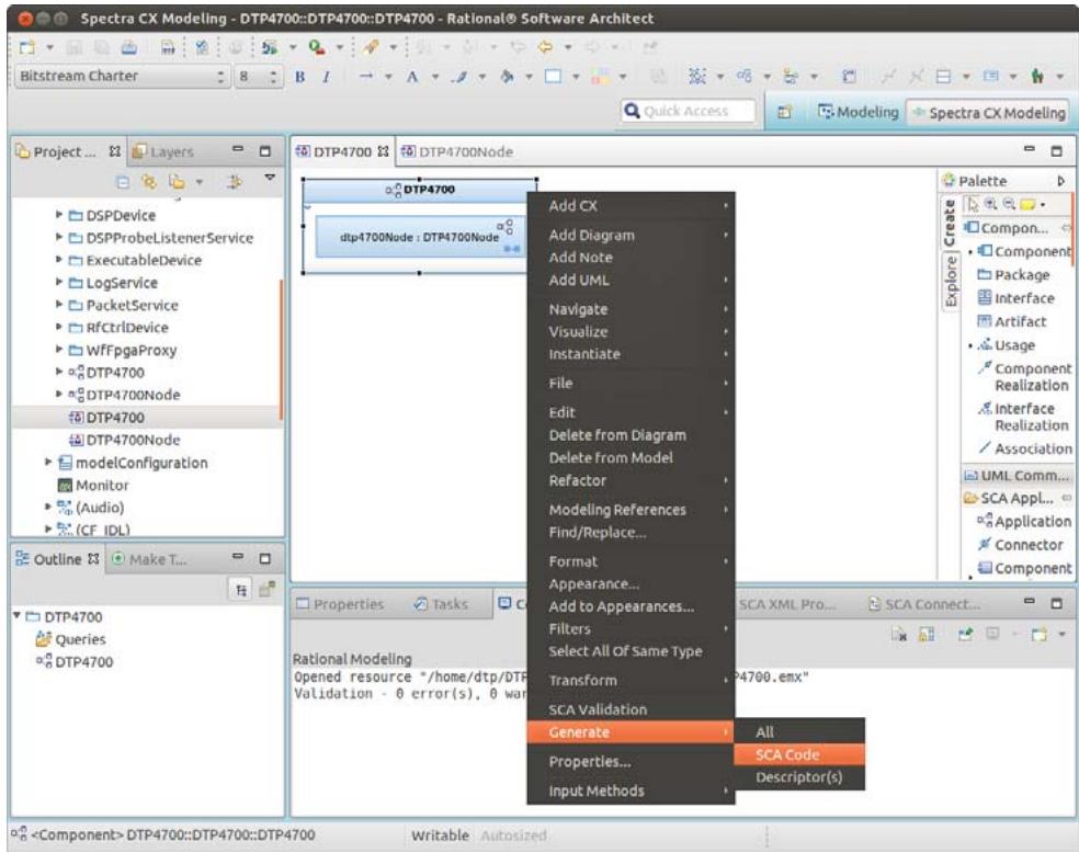
![Spectra CX Modeling - DTP4700::DTP4700::DTP4700 - Rational® Software Architect\nBitstream Charter\nQuick Access\nModeling\nSpectra CX Modeling\nProject...\nLayers\nDSPDevice\nDSPProbeListenerService\nExecutableDevice\nLogService\nPacketService\nRfCtrlDevice\nWffpgaProxy\nDTP4700\nDTP4700Node\nDTP4700\nDTP4700Node\nmodelConfiguration\nMonitor\n(Audio)\n(CF IDL)\nOutline\nMake T...\nDTP4700\nQueries\nDTP4700\nDTP4700\nDTP4700\nAdd CX\nAdd Diagram\nAdd Note\nAdd UML\nNavigate\nVisualize\nInstantiate\nFile\nEdit\nDelete from Diagram\nDelete from Model\nRefactor\nModeling References\nFind/Replace...\nFormat\nAppearance...\nAdd to Appearances...\nFilters\nSelect All Of Same Type\nTransform\nSCA Validation\nGenerate\nAll\nProperties...\nSCA Code\nDescriptor(s)\nRational Modeling\nOpened resource '/home/dtp/DTP'\nValidation - 0 error(s), 0 war\nSCA XML Pro...\nSCA Connect...\n(Component) DTP4700::DTP4700::DTP4700\nWritable: Autosized](.spectra-dtp4700-userguide/874555fc1fc6a4a3ef8693525ab65c91fd52019bf68ea2c3b5dceef8a84a29cb.jpg)

Figure 38 Generating SCA Source Code

Following the generation of descriptors and binaries from the platform model element, the Project Explorer view in Spectra CX will display two new folders in the workspace containing the generated files. The convention for folder names is configurable using Spectra CX, in this case DTP4700\_src will contain the descriptors, and DTP4700\_src\_CPP will contain the binaries. Note in Figure 39 that the code generation procedure also generated the required build instructions resulting in the new elements being displayed in the Make Target view.

i

Please note that the DTP4700 platform models reference existing binaries and therefore no source code will be generated. During generation the pre-existing binaries are copied into the obj directory underneath the source project. If the platform is extended then source code will be generated for any new components.
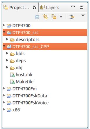
![Project ...\nLayers\nDTP4700\nDTP4700_src\ndescriptors\nDTP4700_src_CPP\nblds\ndeps\nobj\nhost.mk\nMakefile\nDTP4700Fm\nDTP4700FskData\nDTP4700FskVoice\nx86](.spectra-dtp4700-userguide/4d3cbd066c2ff869f75f04e839c1d37518676f7e7a96ab5899207061c9ac95bb.jpg)

Figure 39 Workspace projects containing the generated files

# 8.2.5 Building the DTP4700 Platform

To build the DTP4700 platform:

Step 1: Left-click the DTP4700\_src\_CPP folder in the Make Target view to expand the target elements.

Step 2: Double-click the all target (see Figure 40).

i Please note that as no code is generated for the DTP4700 platform components then during the Make Targets step no code will be compiled. Instead the makefile copies the pre-existing binaries referenced by the components into the obj directory underneath the source project.
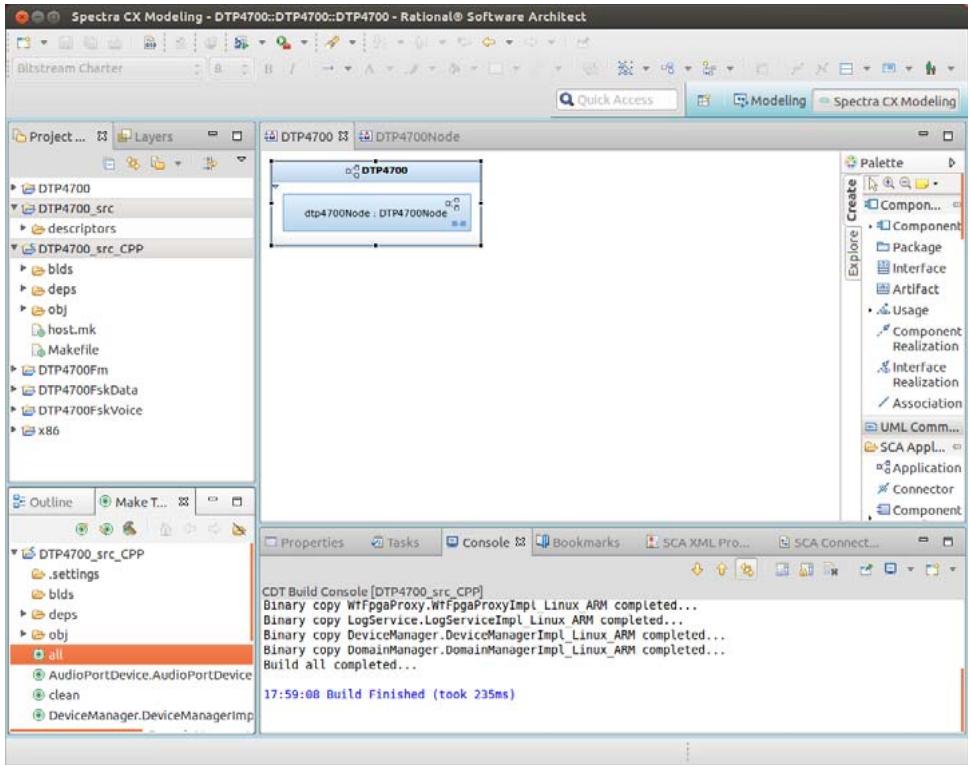
![Spectra CX Modeling - DTP4700::DTP4700::DTP4700 - Rational® Software Architect\nBilstream Charter\nQuick Access\nModeling\nSpectra CX Modeling\nProject ...\nLayers\nDTP4700\nDTP4700Node\nDTP4700\ndtp4700Node : DTP4700Node\nPalette\nCreate\nCompon...\nComponent\nPackage\nInterface\nArtifact\nUsage\nComponent\nRealization\nInterface\nRealization\nAssociation\nUML Comm...\nSCA Appl...\nApplication\nConnector\nComponent\nOutline\nMake T...\nDTP4700_src_CPP\n.settings\nblds\ndeps\nobj\nall\nAudioPortDevice.AudioPortDevice\nclean\nDeviceManager.DeviceManagerImp\nProperties\nTasks\nConsole\nBookmarks\nSCA XML Pro...\nSCA Connect...\nCDT Build Console (DTP4700_src_CPP)\nBinary copy WtFpgaProxy.WtFpgaProxyImpl Linux ARM completed...\nBinary copy LogService.LogServiceImpl Linux ARM completed...\nBinary copy DeviceManager.DeviceManagerImpl Linux ARM completed...\nBinary copy DomainManager.DomainManagerImpl Linux ARM completed...\nBuild all completed...\n17:59:08 Build Finished (took 235ms)](.spectra-dtp4700-userguide/ec2ea87ecbd230c4d9188b06dc9466bc6a3f9ae6be4e9ed8dfe6ba134a4f4142.jpg)

Figure 40 Building the DTP4700 platform

# 8.2.6 Generating the FM Waveform Artefacts

This section describes how to generate profile descriptors and source code for the tutorial FM waveform.

Step 1: In the Project Explorer, expand the folders DTP4700Fm > Models > DTP4700Fm > DTP4700Fm, and double-click the DTP4700Fm diagram model element to display the application assembly diagram as shown in Figure 41.
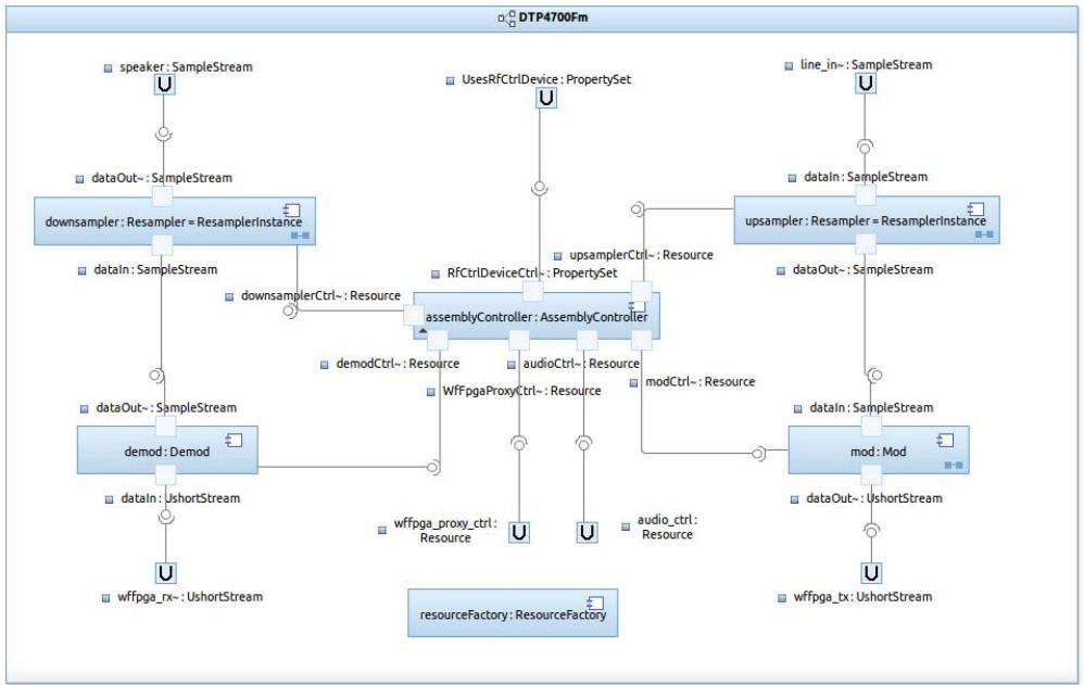
![This flowchart depicts a signal processing architecture featuring an `assemblyController: AssemblyController` that manages data flow and control resources.\n\n**Labeled Blocks:**\n*   `downsampler: Resampler = ResamplerInstance`\n*   `demod: Demod`\n*   `upsampler: Resampler = ResamplerInstance`\n*   `mod: Mod`\n*   `assemblyController: AssemblyController`\n*   `resourceFactory: ResourceFactory` (isolated block at the bottom)\n\n**Connections:**\n\n**Data Flow Paths:**\n*   **Left Path (Receive):**\n    *   `speaker: SampleStream` connects to `dataOut-: SampleStream` of `downsampler: Resampler = ResamplerInstance`.\n    *   `dataIn: SampleStream` of `downsampler: Resampler = ResamplerInstance` connects to `dataOut-: SampleStream` of `demod: Demod`.\n    *   `dataIn: UshortStream` of `demod: Demod` connects to `wffpga_rx~: UshortStream`.\n*   **Right Path (Transmit):**\n    *   `line_in: SampleStream` connects to `dataIn: SampleStream` of `upsampler: Resampler = ResamplerInstance`.\n    *   `dataOut-: SampleStream` of `upsampler: Resampler = ResamplerInstance` connects to `dataIn: SampleStream` of `mod: Mod`.\n    *   `dataOut-: UshortStream` of `mod: Mod` connects to `wffpga_tx~: UshortStream`.\n\n**Control and Resource Connections (Center):**\n*   `UsesRfCtrlDevice: PropertySet` connects to `RfCtrlDeviceCtrl-: PropertySet`, which feeds into `assemblyController: AssemblyController`.\n*   `downsamplerCtrl-: Resource` connects `downsampler: Resampler = ResamplerInstance` to `assemblyController: AssemblyController`.\n*   `upsamplerCtrl-: Resource` connects `upsampler: Resampler = ResamplerInstance` to `assemblyController: AssemblyController`.\n*   `demodCtrl-: Resource` connects `demod: Demod` to `assemblyController: AssemblyController`.\n*   `modCtrl-: Resource` connects `mod: Mod` to `assemblyController: AssemblyController`.\n*   `assemblyController: AssemblyController` connects via `WffpgaProxyCtrl-: Resource` to `wffpga_proxy_ctrl: Resource`.\n*   `assemblyController: AssemblyController` connects via `audioCtrl-: Resource` to `audio_ctrl: Resource`.](.spectra-dtp4700-userguide/bba4ba8544581dc9b049cf1645121dc90269730d4fcb7d37f6374226af841bf8.jpg)

Figure 41 Application Assembly Diagram for the FM waveform

# 8.2.6.1 Generating FM Waveform SCA Descriptors

To generate domain profile descriptors for the FM tutorial waveform, right-click the DTP4700Fm application and then choose Generate > Descriptor(s) from the context menu.
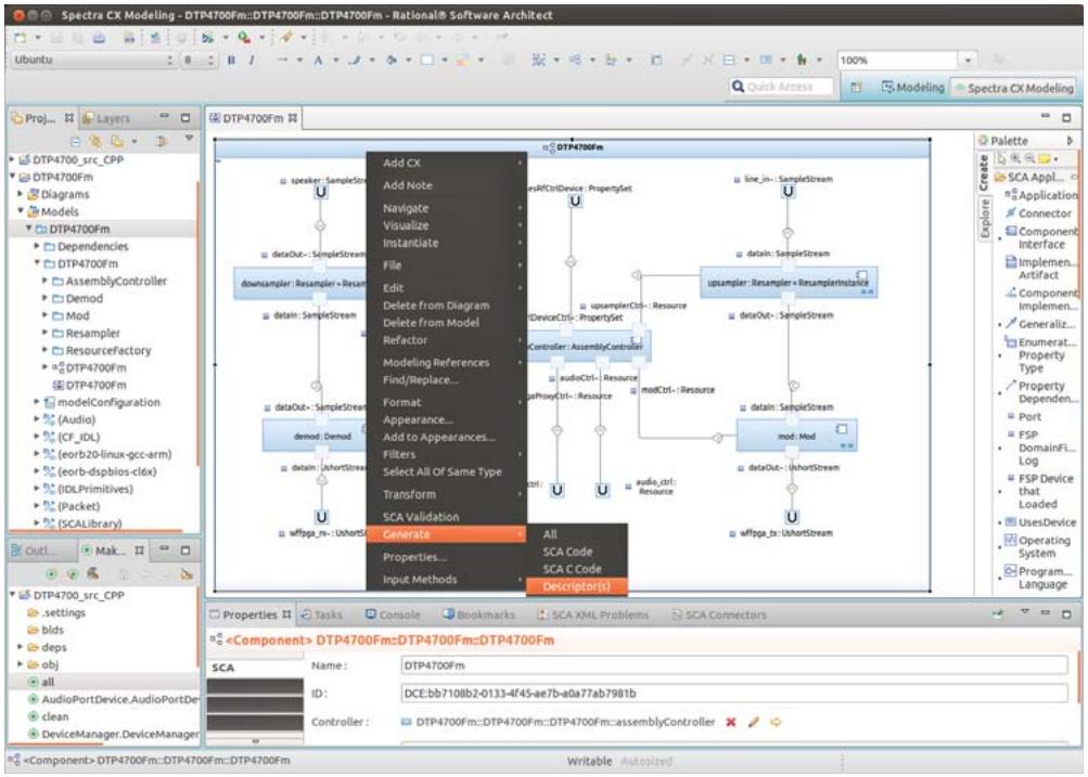
![Spectra CX Modeling - DTP4700Fm::DTP4700Fm::DTP4700Fm - Rational® Software Architect\nUbuntu\n8\nB\nA\n100%\nQuick Access\nModeling\nSpectra CX Modeling\nProj...\nLayers\nDTP4700_src_CPP\nDTP4700Fm\nDiagrams\nModels\nDTP4700Fm\nDependencies\nDTP4700Fm\nAssemblyController\nDemod\nMod\nResampler\nResourceFactory\nDTP4700Fm\nDTP4700Fm\nmodelConfiguration\n(Audio)\n(CF_IDL)\n(eorb20-linux-gcc-arm)\n(eorb-dspbios-clox)\n(IDLPrimitives)\n(Packet)\n(SCALibrary)\nOut1\nMak...\nDTP4700_src_CPP\nsettings\nblds\ndeps\nobj\nall\nAudioPortDevice.AudioPortDes\nclean\nDeviceManager.DeviceManager\nAdd CX\nAdd Note\nNavigate\nVisualize\nInstantiate\nFile\nEdit\nDelete from Diagram\nDelete from Model\nRefactor\nModeling References\nFind/Replace...\nFormat\nAppearance...\nAdd to Appearances...\nFilters\nSelect All Of Same Type\nTransform\nSCA Validation\nGenerate\nProperties...\nInput Methods\nAll\nSCA Code\nSCA C Code\nDescriptor(s)\nSpeaker: SampleStream\ndataOut: SampleStream\ndownsample: Resampler: Resam-\ndatain: SampleStream\ndataOut: SampleStream\ndemod: Demod\ndatain: shortStream\nwfpga_re: shortStream\nLine_in: SampleStream\nDeviceCtrl: PropertySet\nupsampleCtrl: Resource\nController: AssemblyController\naudioCtrl: Resource\nmodCtrl: Resource\ndataOut: SampleStream\ndataout: SampleStream\nmod: Mod\ndataOut: shortStream\nwfpga_re: shortStream\nPalette\nSCA Appl...\nApplication\nConnector\nComponent Interface\nImplement... Artifact...\nComponent Implement...\nGeneraliz...\nEnumerat...\nProperty Type\nProperty Dependen...\nPort FSP DomainFI... Log FSP Device that Loaded UsesDevice Operating System Program... Language](.spectra-dtp4700-userguide/70d9a51f24917b378c9b1ab6d9115c52fb290ec20ad198556761d35728dee82e.jpg)

Figure 42 Generating Descriptors

# 8.2.6.2 Generating FM Waveform SCA Source Code

The DTP4700Fm project contains a combination of C and C++ components. To generate source code for the tutorial FM waveform:

Step 1: To generate C++ code, right-click the DTP4700Fm application and choose Generate > SCA Code from the context menu.
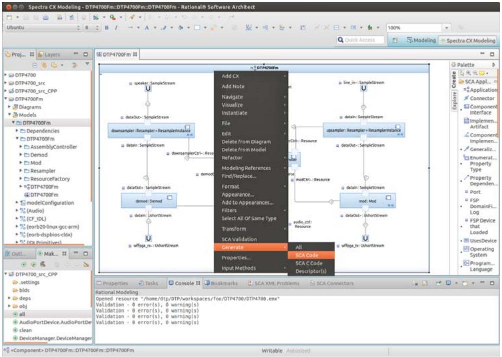
![Spectra CX Modeling - DTP4700Fm::DTP4700Fm::DTP4700Fm - Rational® Software Architect\nUbuntu\nB I A Quick Access Modeling Spectra CX Modeling\nProj... Layers\nDTP4700\nDTP4700_src\nDTP4700_src_CPP\nDTP4700Fm\nDiagrams\nModels\nDTP4700Fm\nDependencies\nDTP4700Fm\nAssemblyController\nDemod\nMod\nResampler\nResourceFactory\nDTP4700Fm\nDTP4700Fm\nmodelConfiguration\n(Audio)\n(CF_IDL)\n(eorb20-linux-gcc-arm)\n(eorb-dspblos-clfx)\n(IDL Primitives)\nOut...\nMak...\nDTP4700_src_CPP\nsettings\nblds\ndeps\nobj\nall\nAudioPortDevice.AudioPortDev\nclean\nDeviceManager.DeviceManager\n(Component) DTP4700Fm::DTP4700Fm::DTP4700Fm\nAdd CX\nAdd Note\nNavigate\nvisualize\nInstantiate\nFile\nEdit\nDelete from Diagram\nDelete from Model\nRefactor\nModeling References\nFind/Replace...\nFormat\nAppearance...\nAdd to Appearances...\nFilters\nSelect All Of Same Type\nTransform\nSCA Validation\nGenerate All\nProperties... SCA Code\nInput Methods SCA C Code Descriptor(s)\nLine_in: SampleStream\ndataOut: SampleStream\nupampler: Resampler = ResamplerInstance\ndataOut: SampleStream\nmodCtrl: Resource\ndataOut: SampleStream\nmod: Mod\ndataOut: UShortStream\nwffpga_tr: UShortStream\nPalette Create\nSCA Appl...\nApplication Connector\nComponent Interface Implement...\nArtifact Component Implement...\nGeneraliz...\nEnumerat...\nProperty Type Property Dependen Port FSP DomainFi... Log FSP Device that Loaded UsesDevice Operating System Program... Language](.spectra-dtp4700-userguide/3b8d30a1441800112c35bca90cdce1395c80025962f7ef1367f2fbee315df584.jpg)

Figure 43 Generating C++ source code

Step 2: To generate C code, right-click the DTP4700Fm application and choose Generate > SCA C Code from the context menu.
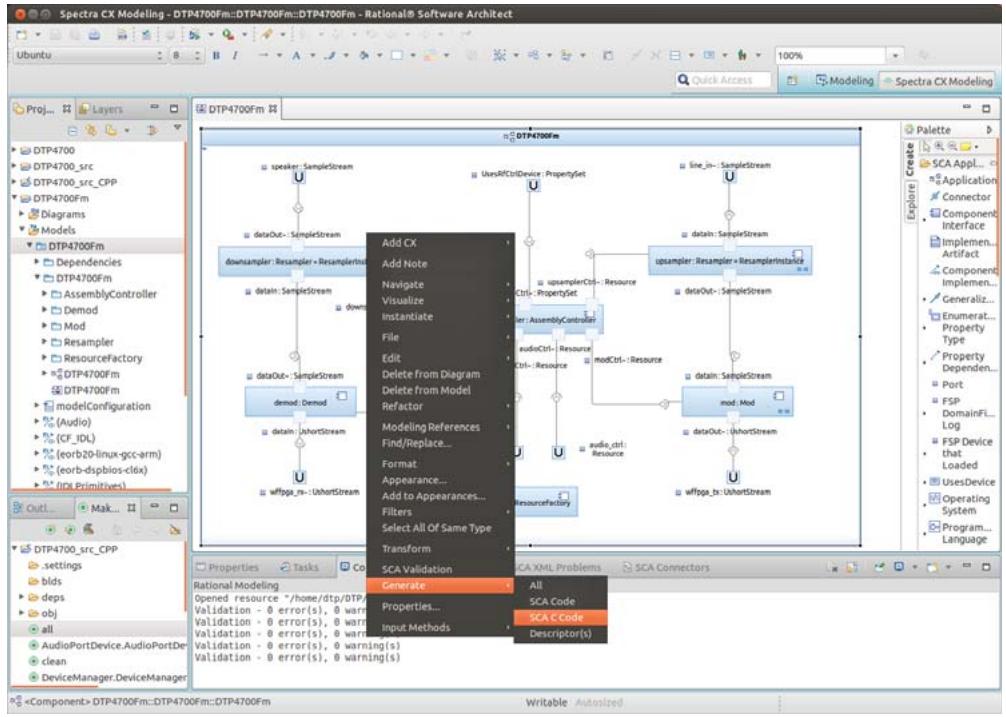
![Based on the provided image, here is the accurate description of the flowchart/block diagram, including labeled blocks and connections. Note that a context menu obscures some text in the center.\n\n**Labeled Blocks:**\n*   `downsamplcr: Resample + ResamplerInst`\n*   `demod: Demod`\n*   `upstream: Resample + ResamplerInst`\n*   `mod: Mod`\n*   `ResourceFactory` (partially visible at the bottom right)\n\n**Connections and Labels:**\n*   **Left Sub-graph:**\n    *   `speaker: SampleStream` connects to `downsamplcr: Resample + ResamplerInst`.\n    *   `downsamplcr: Resample + ResamplerInst` connects to `dataOut: SampleStream`.\n    *   `downsamplcr: Resample + ResamplerInst` connects to `detail: SampleStream`.\n    *   `dataOut: SampleStream` connects to `demod: Demod`.\n    *   `demod: Demod` connects to `wifpga_rs: UbuntuStream`.\n    *   `demod: Demod` connects to `dataIn: UbuntuStream`.\n\n*   **Right Sub-graph:**\n    *   `UsrAtfCtrlDevice: PropertySet` connects to `upsamplCtrl: Resource`.\n    *   `upsamplCtrl: Resource` connects to `upstream: Resample + ResamplerInst`.\n    *   `line_in: SampleStream` connects to `upstream: Resample + ResamplerInst`.\n    *   `upstream: Resample + ResamplerInst` connects to `dataOut: SampleStream`.\n    *   `upstream: Resample + ResamplerInst` connects to `mod: Mod`.\n    *   `mod: Mod` connects to `dataIn: UbuntuStream`.\n    *   `mod: Mod` connects to `wifpga_rs: UbuntuStream`.\n\n*   **Obscured Connections (Center):**\n    *   Several connections point to `upstream: Resample + ResamplerInst` from obscured blocks labeled (partially visible):\n        *   `demCtrl: AssemblyController`\n        *   `audioCtrl: Resource`\n        *   `modCtrl: Resource`\n        *   `audle_ctrl: Resource`](.spectra-dtp4700-userguide/5e34abc6a166bf63f2f5e3628c73ad9a537862947a5f2b537c07449775f51c61.jpg)

Figure 44 Generating C source code

i Both C and C++ code, as well as descriptors, can also be generated by choosing Generate > All.

When the waveform descriptors and SCA code have been generated, projects containing the generated files will appear in the Project Explorer view:

DTP4700Fm\_src contains the descriptor files

DTP4700Fm\_src\_CPP contains the C++ code files

DTP4700Fm\_src\_C contains the C code files
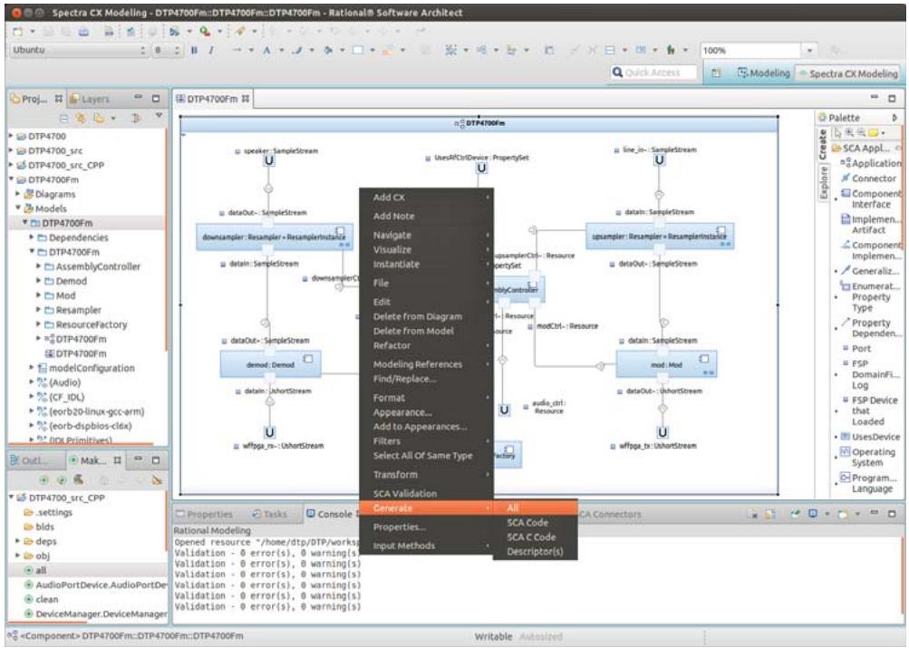
![Spectra CX Modeling - DTP4700Fm::DTP4700Fm::DTP4700Fm - Rational® Software Architect\nUbuntu\nQuick Access\nModeling\nSpectra CX Modeling\nProj...\nLayers\nDTP4700\nDTP4700_src\nDTP4700_src_CPP\nDTP4700Fm\nDiagrams\nModels\nDTP4700Fm\nDependencies\nDTP4700Fm\nAssemblyController\nDemod\nMod\nResampler\nResourceFactory\nDTP4700Fm\nDTP4700Fm\nmodelConfiguration\n(Audio)\n(CF_IDL)\n(eorb20-linux-gcc-arm)\n(eorb-dspbios-clfx)\n(IDL Primitives)\nOut...\nMak...\nDTP4700_src_CPP\nsettings\nblds\ndeps\nobj\nall\nAudioPortDevice.AudioPortDev\nclean\nDeviceManager.DeviceManager\n(TComponent) DTP4700Fm::DTP4700Fm::DTP4700Fm\nAdd CX\nAdd Note\nNavigate\nVisualize\nInstantiate\nFile\nEdit\nDelete from Diagram\nDelete from Model\nRefactor\nModeling References\nFind/Replace...\nFormat\nAppearance...\nAdd to Appearances...\nFilters\nSelect All Of Same Type\nTransform\nSCA Validation\nGenerate\nProperties...\nInput Methods\nAll\nSCA Code\nSCA C Code\nDescriptor(s)\nLine_in - SampleStream\ndataOut - SampleStream\nupampler: Resampler = ResamplerInstance\nupamplerCn - Resource\nPropertySet\nmyController\nresenlty\nresenlty\nresenlty\nresenlty\nresenlty\nresenlty\nresenlty\nresenlty\nresenlty\nresenlty\nresenlty\nresenlty\nresenlty\nresenlty\nresenlty\nresenlty\nresenlty\nresenlty\nresenlty\nresenlty\nresenltry\naudio_ctrl:\nresource\ndataOut - UshortStream\naffpga_tr: UshortStream\naffpga_tr: UshortStream](.spectra-dtp4700-userguide/7d374bfab46a7f2ee8e730247cc125aa4b5038fe79f8544594fe15cc4b4a131a.jpg)

Figure 45 Generating All

Figure 46 shows the generated projects in the Project Explorer.
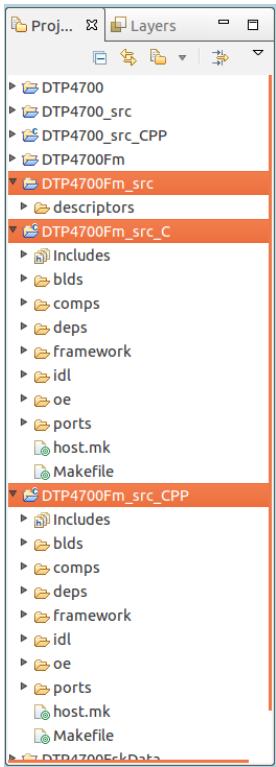
![DTP4700\nDTP4700_src\nDTP4700_src_CPP\nDTP4700Fm\nDTP4700Fm_src\ndescriptors\nDTP4700Fm_src_C\nIncludes\nblds\ncomps\ndeps\nframework\nidl\noe\nports\nhost.mk\nMakefile\nDTP4700Fm_src_CPP\nIncludes\nblds\ncomps\ndeps\nframework\nidl\noe\nports\nhost.mk\nMakefile](.spectra-dtp4700-userguide/7901c1d1c61a1d410ead35661b3cd9155adc732383b6893631643e201edb6355.jpg)

Figure 46 Generated projects

# 8.2.7 Building the FM Waveform

To build the waveform:

Step 1: Click to expand the DTP4700Fm\_src\_CPP folder in the Make Target view.
Step 2: Double-click on the all target element to compile and link the C++ source code.
Step 3: Click to expand the DTP4700Fm\_src\_C folder in the Make Target view.
Step 4: Double-click on the all target element to compile and link the C source code.
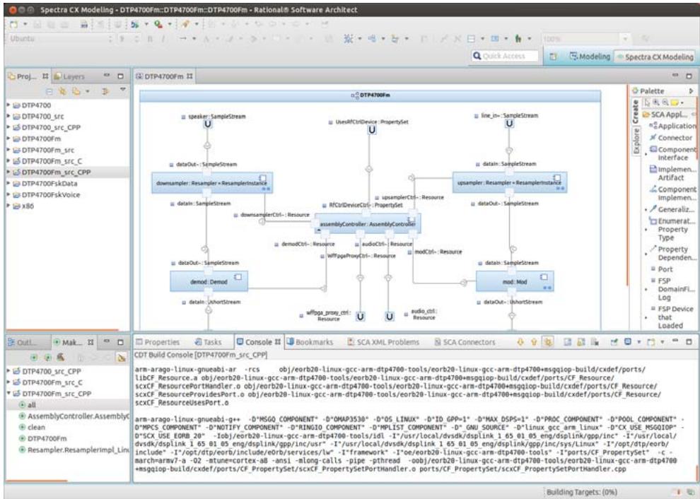
![Spectra CX Modeling - DTP4700Fm::DTP4700Fm::DTP4700Fm - Rational® Software Architect\nUmbuts\nQuick Access\nModeling\nSpectra CX Modeling\nProj...\nLayers\nDTP4700\nDTP4700_src\nDTP4700_src_CPP\nDTP4700Fm\nDTP4700Fm_src_C\nDTP4700Fm_src_CPP\nDTP4700FskData\nDTP4700FskVoice\nX86\nDTP4700Fm\nspeaker: SampleStream\nUswRfCtrlDevice: PropertySet\nLine In: SampleStream\ndataOut: SampleStream\ndownsample: Resampler + ResamplerInstance\nupsampler: Resampler - ResamplerInstance\ndataIn: SampleStream\nNfCtrlDeviceCtrl: PropertySet\ndataOut: SampleStream\ndownsampleCtrl: - Resource\nassemblyController: AssemblyController\ndemodCtrl: - Resource\naudioCtrl: - Resource\nmodCtrl: - Resource\ndataOut: SampleStream\ndataOut: SampleStream\ndemod: Demod\ndataIn: ShortStream\nmod: Mod\ndataOut: ShortStream\nProperties Tasks Console Bookmarks SCA XML Problems SCA Connectors\nCDT Build Console (DTP4700Fm_src_CPP)\narm-arago-linux-gneabri-ar -rcs obj/eorb20-linux-gcc-arm-dtp4700-tools/eorb20-linux-gcc-arm-dtp4700+msgqiop-build/ cxdef/ports/\nlibCF_Resource.a obj/eorb20-linux-gcc-arm-dtp4700-tools/eorb20-linux-gcc-arm-dtp4700+msgqiop-build/ cxdef/ports/CF_Resource/\nscxCF_ResourcePortHandler.o obj/eorb20-linux-gcc-arm-dtp4700-tools/eorb20-linux-gcc-arm-dtp4700+msgqiop-build/ cxdef/ports/CF_Resource/\nscxCF_ResourceProvidesPort.o obj/eorb20-linux-gcc-arm-dtp4700-tools/eorb20-linux-gcc-arm-dtp4700+msgqiop-build/ cxdef/ports/CF_Resource/\nscxCF_ResourceUsesPort.o\narm-arago-linux-gneabri-g++ -D*MSGO COMPONENT* -D*OMAP3530 * -D*OS LINUX * -D*ID GPP=1 * -D*MAX DSPS=1 * -D*PROC COMPONENT* -D*POOL COMPONENT*\n- D*MPCS COMPONENT* -D*NOTIFY COMPONENT* -D*RINGIO COMPONENT* -D*MPLIST COMPONENT* -D* GNU SOURCE* -D*linux gcc arm linux* -D*CX USE MSGQIOP*\n- D*SCX USE EORB 20 * -Iob/eorb20-linux-gcc-arm-dtp4700-tools/idl -I*usr/local/dvsdk/dsplink 1.65 01 05 eng/dsplink/gpp/inc*\n- D*user/local/\ndvsdk/dsplink 1.65 01 05 eng/dsplink/gpp/inc/usr*\n- I*user/local/\ndvsdk/dsplink 1.65 01 05 eng/dsplink/gpp/inc/sys/Linux*\n- I*/opt/dtp/eorb/\ninclude* -I*/opt/dtp/eorb/include/eorb/services/lw* -I*framework* -I*oe/eorb20-linux-gcc-arm-dtp4700-tools*\n- I*ports/CF PropertySet * c -\nmarch=armv7-a -O2 -sture=cortex-ab -ansi -along-calls -pipe -pthread -oobj/eorb20-linux-gcc-arm-dtp4700-tools/eorb20-linux-gcc-arm-dtp4700\n+msgqiop-build/ cxdef/ports/CF PropertySet/scxCF PropertySetPortHandler.o ports/CF PropertySet/scxCF PropertySetPortHandler.cpp\nBuilding Targets: (0%)](.spectra-dtp4700-userguide/d4b071e24e5f1cd775935b7a5768ee6a052bdc44921c853c3794d94fed05fbd1.jpg)

Figure 47 Compiling and Linking

# 8.2.8 Packaging XML and Binaries for Deployment

Before running the generated platform and waveform it is first necessary to package the generated XML and binaries into a bundle on the target file system which is suitable for deployment.

# 8.2.8.1 Platform

Step 1: Open the Ubuntu File Browser by clicking the Home Folder icon on the Unity Launcher.

Step 2: From the Computer list in the File Browser select File System.

Step 3: Navigate to the target file system: mnt > targetfs.

Step 4: Navigate to the opt > dtp > platform directory on the target file system.

Step 5: In Spectra CX select the platform descriptors folder (found under the DTP4700\_src project) and drag the folder into the platform directory in the Ubuntu file browser.

Step 6: In the Ubuntu File Browser rename the descriptors folder to be xml-DTP4700-tutorial.

i The generated XML is configured to expect the platform binaries to be in the ../bin directory. As the platform binaries are already present in the appropriate location there is no need to copy the binaries onto the target file system.

# 8.2.8.2 Waveform

Step 1: Open the Ubuntu File Browser by clicking the Home Folder icon on the Unity Launcher.

Step 2: From the Computer list in the File Browser select File System.

Step 3: Navigate to the target file system: mnt > targetfs.

Step 4: Navigate to the opt > dtp > applications directory on the target file system.

Step 5: In Spectra CX select the waveform descriptors folder (found under the DTP4700Fm\_src project) and drag the folder into the applications directory in the Ubuntu file browser.

Step 6: In the Ubuntu File Browser rename the descriptors folder to be DTP4700Fm-tutorial.

Step 7: Copy the Demod.out, Mod.out and ResourceFactory.out binaries from Spectra CX (found under the obj directory in the DTP4700Fm\_src\_C project) to the DTP4700Fm-tutorial directory in the Ubuntu File Browser.

Step 8: Copy the AssemblyController and Resampler binaries from Spectra CX (found under the obj directory in the DTP4700Fm\_src\_CPP project) to the DTP4700Fm-tutorial directory on the Ubuntu File Browser.

# 8.2.9 Creating a DTP4700 SD Card

A utility script (mksdboot.sh) is provided in the /opt/dtp/bin directory of the LiveUSB system to create a bootable SD card for the DTP4700 system. Please refer to Section 3.1.1.5, Utility Scripts, on page 16, for instructions on using this script.

The script will create a file system consisting of the TI Linux operating system and a copy of the target file system from the host. The target file system contains several platform and waveforms including the ones copied onto the target file system in Section 8.2.8, Packaging XML and Binaries for Deployment, on page 87.

i When running the mksdboot.sh script you will be asked to choose which platform version you would like to be run when the target system boots. Select 3: Other and then enter xml-DTP4700-tutorial as the name of the platform.

Ensure the SD card is plugged into the Thunder system’s SD/MMC slot before booting the target system.

# 8.2.10 Running the FM Waveform

This section describes how to run the compiled example FM Waveform on the DTP4700 platform.

# 8.2.10.1 Configuring Ubuntu Host Network

By default the Ubuntu host system is configured to acquire an IP address via DHCP, but the Thunder system is configured with a static IP address. In such a configuration the two systems will not be able to communicate.

To configure the Ubuntu host system with a static IP address compatible with the Thunder target:

Step 1: Left-click the PrismTech icon on the system menu to activate the PrismTech menu.

Step 2: From the PrismTech menu choose Spectra > IP Address > Switch to Static IP.
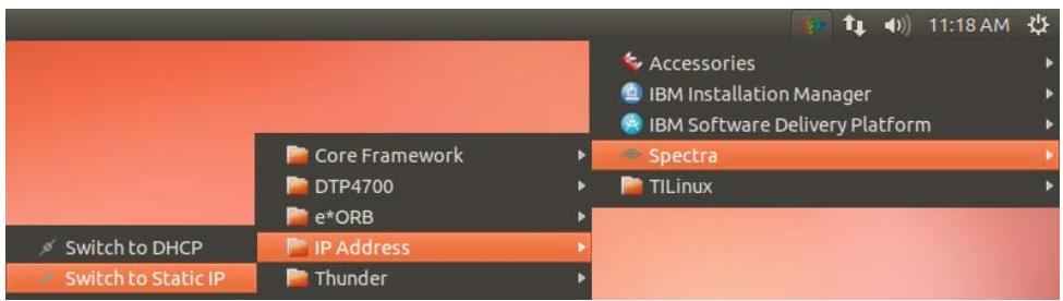
![Switch to DHCP\nSwitch to Static IP\nCore Framework\nDTP4700\ne*ORB\nIP Address\nThunder\n11:18 AM\nAccessories\nIBM Installation Manager\nIBM Software Delivery Platform\nSpectra\nTILinux](.spectra-dtp4700-userguide/753306fbc873bc4ada31b9bfd9a4c07053c717ef39015e4d205b2a91b46c9400.jpg)

Figure 48 Setting a static IP address

# 8.2.10.2 Connecting Spectra CX Monitor to DTP4700

The monitor object in the model contains details of the DTP4700 and how to connect to it. The details of how to connect to a NameService and the name under which the SCA DomainManager is registered is contained in the Monitor. The values can be modified if required.

To connect to the platform, first open the SCA Monitor:

Step 1: In the Project Explorer, expand the folders DTP4700 > Models > DTP4700, and right-click on Monitor.

Step 2: Choose Open SCA Monitor (see Figure 49).
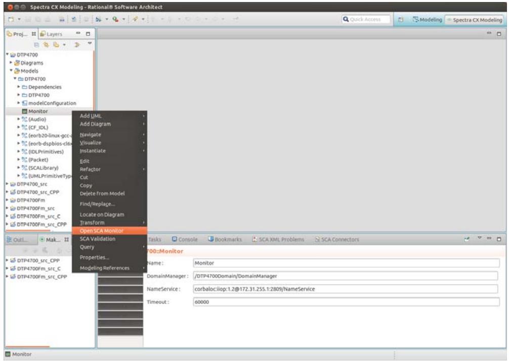
![Spectra CX Modeling - Rational® Software Architect\nQuick Access\nModeling\nSpectra CX Modeling\nProj...\nLayers\nDTP4700\nDiagrams\nModels\nDTP4700\nDependencies\nDTP4700\nmodelConfiguration\nMonitor\n(Audio)\n(CF_IDL)\n(eorb20-linux-gcc-\n(eorb-dspbios-clux-\n(IDLPrimitives)\n(Packet)\n(SCALibrary)\n(UMLPrimitiveType\nDTP4700_src\nDTP4700_src_CPP\nDTP4700Fm\nDTP4700Fm_src\nDTP4700Fm_src_C\nDTP4700Fm_src_CPP\nAdd UML\nAdd Diagram\nNavigate\nVisualize\nInstantiate\nEdit\nRefactor\nCut\nCopy\nDelete from Model\nFind/Replace_\nLocate on Diagram\nTransform\nOpen SCA Monitor\nSCA Validation\nQuery\nProperties...\nModeling References\nTasks Console Bookmarks SCA XML Problems SCA Connectors\n700::Monitor\nName: Monitor\nDomainManager : /DTP4700Domain/DomainManager\nNameService : corbalociliop.1.2@172.31.255.1:2809/NameService\nTimeout: 60000\nMonitor](.spectra-dtp4700-userguide/aad0597f170e1190fd65a74c28a6a5ed37dab7ace37f78704557daeb5c18134b.jpg)

Figure 49 Opening the SCA Monitor

Connecting to the DTP4700 will display the running SCA platform, as shown in Figure 50.
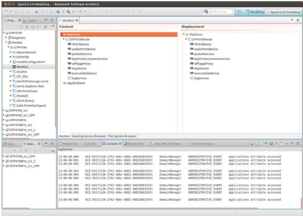
![Spectra CX Modeling - - Rational® Software Architect\nQuick Access\nModeling\nSpectra CX Modeling\nProj...\nLayers\nMonitor\nControl\nPlatform\nDTP4700Node\nrfCtrlDevice\naudioPortDevice\npacketService\ndspProbeListenerService\nwffpgaProxy\ndspDevice\nexecutableDevice\nlogService\nApplications\nDeployment\nPlatform\nDTP4700Node\nrfCtrlDevice\naudioPortDevice\npacketService\ndspProbeListenerService\nwffpgaProxy\ndspDevice\nexecutableDevice\nlogService\nMonitor | Naming Service Browser | File System Browser |\nOut...\nMake...\nProperties | Tasks | Console | Bookmarks | SCA XML Problems | SCA Connectors\nlogService\n13:08:08:980 DCE:591f1136-2f42-46bc-8862-d0829b0319fc DomainManager ADMINISTRATIVE_EVENT applications attribute accessed\n13:08:08:981 DCE:591f1136-2f42-46bc-8862-d0829b0319fc DomainManager ADMINISTRATIVE_EVENT applications attribute accessed\n13:08:08:982 DCE:591f1136-2f42-46bc-8862-d0829b0319fc DomainManager ADMINISTRATIVE_EVENT applications attribute accessed\n13:08:08:983 DCE:591f1136-2f42-46bc-8862-d0829b0319fc DomainManager ADMINISTRATIVE_EVENT applications attribute accessed\n13:08:08:983 DCE:591f1136-2f42-46bc-8862-d0829b0319fc DomainManager ADMINISTRATIVE_TIME applications attribute accessed\n13:08:08:984 DCE:591f1136-2f42-46bc-8862-d0829b0319fc DomainManager ADMINISTRATIVE_EVENT applications attribute accessed\n13:08:08:984 DCE:591f1136-2f42-46bc-8862-d0829b0319fc DomainManager ADMINISTRATIVE_EVENT applications attribute accessed\n13:08:08:985 DCE:591f1136-2f42-46bc-8862-d0829b0319fc DomainManager ADMINISTRATIVE_EVENT applications attribute accessed\n13:08:08:985 DCE:591f1136-2f42-46bc-8862-d0829b0319fc DomainManager ADMINISTRATIVE_TIME applications attribute accessed](.spectra-dtp4700-userguide/71254b6e48708b5bd7bfa30214e06ea2d60f32941a8128505c46e3407fd8d16a.jpg)

Figure 50 Monitor showing running SCA platform

i In the Monitor view, the DomainManager and DeviceManager are implicit, and are therefore not displayed in the Control or Deployment panes.

# 8.2.10.3 Installing the FM Waveform

To install the FM Waveform:

Step 1: Right-click Applications and from the pop-up menu choose Install Application Factory.

Step 2: Select /DTP4700Domain/DTP4700Node/applications/DTP4700Fm-tutorial/DTP4700Fm.s ad.xml
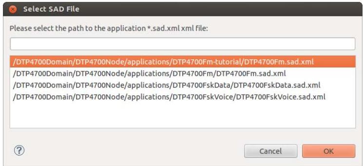
![/DTP4700Domain/DTP4700Node/applications/DTP4700Fm-tutorial/DTP4700Fm.sad.xml\n/DTP4700Domain/DTP4700Node/applications/DTP4700Fm/DTP4700Fm.sad.xml\n/DTP4700Domain/DTP4700Node/applications/DTP4700FskData/DTP4700FskData.sad.xml\n/DTP4700Domain/DTP4700Node/applications/DTP4700FskVoice/DTP4700FskVoice.sad.xml](.spectra-dtp4700-userguide/b71e493a3d5f4e407e7760ad2b0e6dc4437332cda7f9cd13ac185bc98dbdbbb2.jpg)

Figure 51 Installing the FM Waveform

# Step 3: Click OK.

When the application is successfully installed, its Application Factory is displayed in the Control pane (see Figure 52).
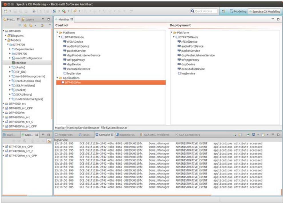
![Spectra CX Modeling - - Rational® Software Architect\nQuick Access\nModeling\nSpectra CX Modeling\nProj...\nLayers\nMonitor\nControl\nDeployment\nPlatform\nDTP4700Node\nrfCtrlDevice\naudioPortDevice\npacketService\ndspProbeListenerService\nwffpgaProxy\ndspDevice\nexecutableDevice\nlogService\nApplications\nDTP4700Fm\nPlatform\nDTP4700Node\nrfCtrlDevice\naudioPortDevice\npacketService\ndspProbeListenerService\nwffpgaProxy\ndspDevice\nexecutableDevice\nlogService\nMonitor | Naming Service Browser | File System Browser |\nOut...\nMak...\nProperties | Tasks | Console | Bookmarks | SCA XML Problems | SCA Connectors\nlogService\n13:10:55:993 DCE:591f1136-2f42-46bc-8862-d0829b0319fc DomainManager ADMINISTRATIVE_EVENT applications attribute accessed\n13:10:55:994 DCE:591f1136-2f42-46bc-8862-d0829b0319fc DomainManager ADMINISTRATIVE_EVENT applications attribute accessed\n13:10:55:995 DCE:591f1136-2f42-46bc-8862-d0829b0319fc DomainManager ADMINISTRATIVE_EVENT applications attribute accessed\n13:10:55:996 DCE:591f1136-2f42-46bc-8862-d0829b0319fc DomainManager ADMINISTRATIVE_EVENT applications attribute accessed\n13:10:55:997 DCE:591f1136-2f42-46bc-8862-d0829b0319fc DomainManager ADMINISTRATIVE_EVENT applications attribute accessed\n13:10:55:998 DCE:591f1136-2f42-46bc-8862-d0829b0319fc DomainManager ADMINISTRATIVE_EVENT applications attribute accessed\n13:10:55:999 DCE:591f1136-2f42-46bc-8862-d0829b0319fc DomainManager ADMINISTRATIVE_EVENT applications attribute accessed\n13:10:56:000 DCE:591f1136-2f42-46bc-8862-d0829b0319fc DomainManager ADMINISTRATIVE_EVENT applications attribute accessed\n13:10:56:000 DCE:591f1136-2f42-46bc-8862-d0829b0319fc DomainManager ADMINISTRATIVE_TEXT applications attribute accessed\n13:10:56:005 DCE:591f1136-2f42-46bc-8862-d0829b0319fc DomainManager ADMINISTRATIVE_EVENT applications attribute accessed\n13:10:56:005 DCE:591f1136-2f42-46bc-8862-d0829b0319fc DomainManager ADMINISTRATIVE_EVENT applications attribute accessed](.spectra-dtp4700-userguide/aedcddc0ca066479aa23869c5d1fe8c87ca0df1200219a51badc152e4edeb719.jpg)

Figure 52 FM Waveform successfully installed

# 8.2.10.4 Creating the FM Waveform

To create an instance of the FM Waveform from the installed Application Factory:

Step 1: Right-click the DTP4700Fm application and choose Create Application.

Step 2: Enter a name for the instance (for this example, the name is “a1”).
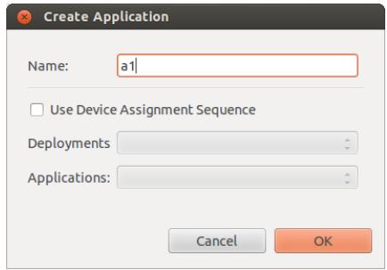
![Create Application\nName: a1\nUse Device Assignment Sequence\nDeployments\nApplications:\nCancel OK](.spectra-dtp4700-userguide/d0817a4d8baa5d2b36104d129f98ca705f35f5acf57c4f7022e4a4f9d4f82918.jpg)

Figure 53 Naming the new application instance

Step 3: Click OK.
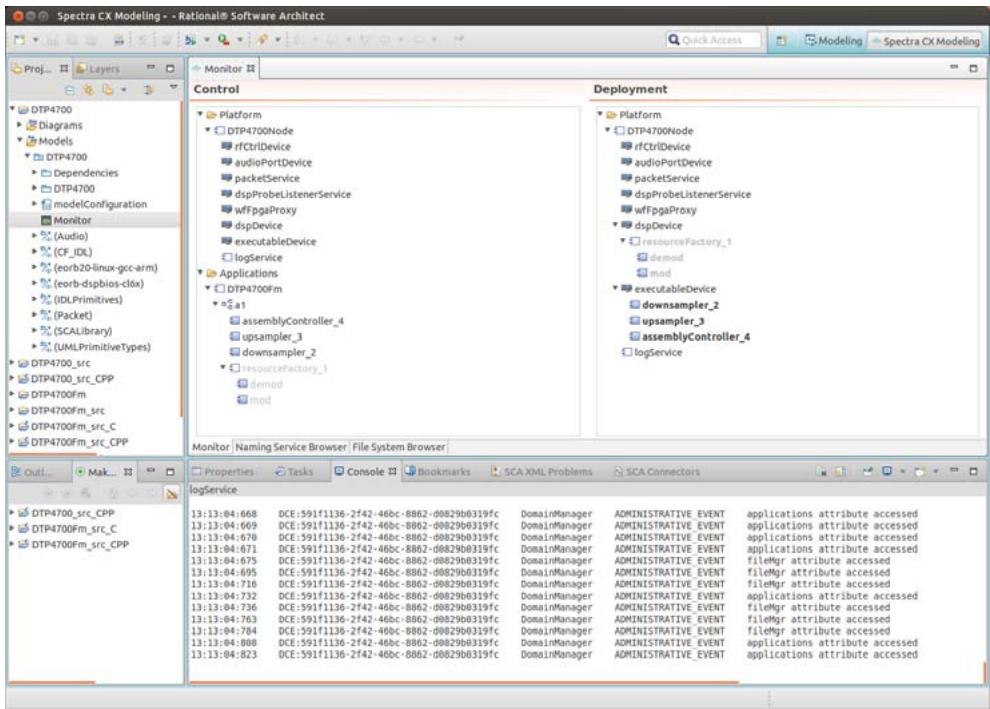
![Spectra CX Modeling - - Rational® Software Architect\nQuick Access\nModeling\nSpectra CX Modeling\nProj...\nLayers\nMonitor\nControl\nDeployment\nPlatform\nDTP4700Node\nrfCtrlDevice\naudioPortDevice\npacketService\ndspProbeListenerService\nwffpgaProxy\ndspDevice\nexecutableDevice\nlogService\nApplications\nDTP4700Fm\na1\nassemblyController_4\nupsampler_3\ndownsampler_2\nresourceFactory_1\ndemod\nmod\nPlatform\nDTP4700Node\nrfCtrlDevice\naudioPortDevice\npacketService\ndspProbeListenerService\nwffpgaProxy\ndspDevice\nresourceFactory_1\ndemod\nmod\nexecuteableDevice\ndownsampler_2\nupsampler_3\nassemblyController_4\nlogService\nMonitor | Naming Service Browser | File System Browser |\nOut...\nMak...\nProperties | Tasks | Console | Bookmarks | SCA XML Problems | SCA Connectors\nlogService\nDTP4700_src_CPP\nDTP4700Fm_src_C\nDTP4700Fm_src_CPP\n13:13:04:668 DCE:591f1136-2f42-46bc-8862-d0829b0319fc DomainManager ADMINISTRATIVE EVENT applications attribute accessed\n13:13:04:669 DCE:591f1136-2f42-46bc-8862-d0829b0319fc DomainManager ADMINISTRATIVE EVENT applications attribute accessed\n13:13:04:670 DCE:591f1136-2f42-46bc-8862-d0829b0319fc DomainManager ADMINISTRATIVE EVENT applications attribute accessed\n13:13:04:671 DCE:591f1136-2f42-46bc-8862-d0829b0319fc DomainManager ADMINISTRATIVE EVENT applications attribute accessed\n13:13:04:672 DCE:591f1136-2f42-46bc-8862-d0829b0319fc DomainManager ADMINISTRATIVE EVENT applications attribute accessed\n13:13:04:736 DCE:591f1136-2f42-46bc-8862-d0829b0319fc DomainManager ADMINISTRATIVE EVENT fileMgr attribute accessed\n13:13:04:763 DCE:591f1136-2f42-46bc-8862-d0829b0319fc DomainManager ADMINISTRATIVE EVENT fileMgr attribute accessed\n13:13:04:784 DCE:591f1136-2f42-46bc-8862-d0829b0319fc DomainManager ADMINISTRATIVE EVENT fileMgr attribute accessed\n13:13:04:808 DCE:591f1136-2f42-46bc-8862-d0829b0319fc DomainManager ADMINISTRATIVE EVENT applications attribute accessed\n13:13:04:823 DCE:591f1136-2f42-46bc-8862-d0829b0319fc DomainManager ADMINISTRATIVE EVENT applications attribute accessed](.spectra-dtp4700-userguide/c029534952578f7f9a0ba695d372ae887ae4e17aa2aa9dc0030cdc7c94e59466.jpg)

Figure 54 Successful creation of an application instance

Figure 54 shows a successful instantiation of the DTP4700Fm application. The Deployment pane shows the instantiated waveform components of the application a1 running on the DTP4700 SCA platform components.

i The components that were deployed on the DSP device appear greyed-out in the Monitor as these components do not implement the IIOP transport profile so the Monitor cannot communicate with them. In such a case the Monitor displays only the information present in the XML descriptors for the component. The cfadmin utility that runs on the Thunder target hardware can be used to view the details of all running waveform components including those based on transports other than IIOP. Please refer to Section 8.3, Running the FM Tutorial using cfadmin, on page 102 for more details.

# 8.2.10.5 Starting the FM Waveform

To start the newly-created instance of the application:

Step 1: Set the Transmit Frequency.

Select the rfCtrlDevice in the Control pane and switch to the Properties view, then select the SCA Properties tab. Select the txFrequency property and set the value to the frequency you wish to transmit on.

![The image displays a standard warning symbol consisting of a red triangle with a thick border. Inside the triangle is a black exclamation point.](.spectra-dtp4700-userguide/0cc1bb3ae7bc92901278f8fcc247b2d1dcde00a603348f1ac0b17cf564b0308c.jpg)

NOTE: If transmitting over the air, please ensure that the frequency chosen is legal in your country.

Step 2: Set the Receive Frequency.

Select the rfCtrlDevice in the Control pane and switch to the Properties view, then select the SCA Properties tab. Select the rxFrequency property and set the value to the frequency you wish to transmit on.

i To run the application in loopback mode the transmit and receive frequencies must be compatible. This could be achieved by setting the Rx and Tx frequencies to the same value. However it is recommended that the Rx frequency should be configured to be +60Hz or -60Hz of the Tx frequency. Please refer to the DTP4700 Release Notes for more details.
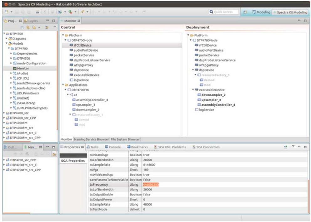
![Spectra CX Modeling -- Rational® Software Architect\nQuick Access\nModeling\nSpectra CX Modeling\nProj...\nLayers\nMonitor\nControl\nPlatform\nDTP4700Node\nrfCtrlDevice\naudioPortDevice\npacketService\ndspProbeListenerService\nwffpgaProxy\ndspDevice\nexecutableDevice\nlogService\nApplications\nDTP4700Fm\na1\nassemblyController_4\nupsampler_3\ndownsampler_2\nresourceFactory_1\ndemod\nmod\nDeployment\nPlatform\nDTP4700Node\nrfCtrlDevice\naudioPortDevice\npacketService\ndspProbeListenerService\nwffpgaProxy\ndspDevice\nresourceFactory_1\ndemod\nmod\nexecutableDevice\ndownsampler_2\nupsampler_3\nassemblyController_4\nlogService\nMonitor\nNaming Service Browser: File System Browser\nOut...\nMake...\nProperties\nTasks\nConsole\nBookmarks\nSCA XML Problems\nSCA Connectors\nSCA Properties\nrxInbandAgc\nrxLpfBandwidth\nrxSampleRate\nrxVga\nrxWidebandAgc\nsaveParamsToNonVolatile\ntxFrequency\ntxLpfBandwidth\ntxOutputEnable\ntxOutputPower\ntxSampleRate\ntxTestMode\nBoolean true\nUlong 20000\nUlong 6144000\nShort 189\nBoolean true\nBoolean false\nUlong 540000350\nUlong 20000\nBoolean false\nShort 0\nUlong 48000\nUshort 0](.spectra-dtp4700-userguide/debf3ffbf0ff31486c93269b19e89e3418daff50974120989719912aad3d21c4.jpg)

Figure 55 Setting the Transmit Frequency

Step 3: Choose Start from the application’s context menu.
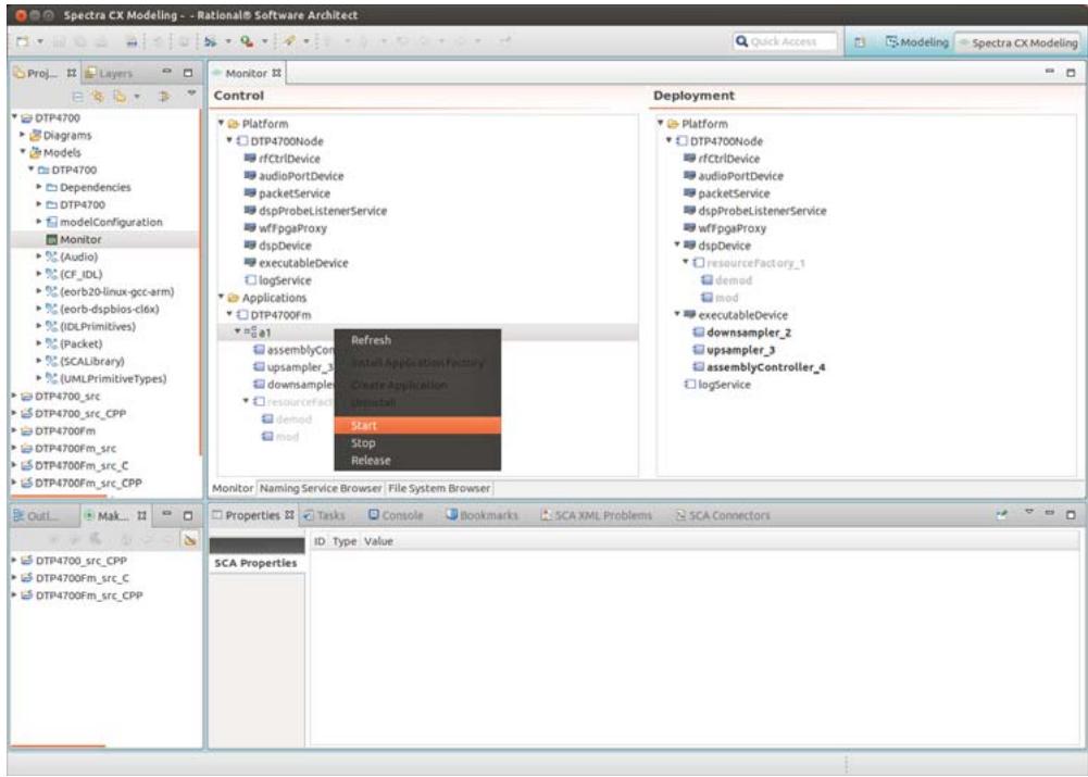
![Spectra CX Modeling -- Rational® Software Architect\nQuick Access\nModeling\nSpectra CX Modeling\nProj...\nLayers\nMonitor\nControl\nPlatform\nDTP4700Node\nrfCtrlDevice\naudioPortDevice\npacketService\ndspProbeListenerService\nwffpgaProxy\ndspDevice\nexecutableDevice\nlogService\nApplications\nDTP4700fm\na1\nassemblyCont\nupsampler_3\ndownsample\nresourcefact\ndemod\nmod\nRefresh\nInstall Application Facility\nCreate Application\nupinstall\nStart\nStop\nRelease\nDeployment\nPlatform\nDTP4700Node\nrfCtrlDevice\naudioPortDevice\npacketService\ndspProbeListenerService\nwffpgaProxy\ndspDevice\nresourceFactory_1\ndemod\nmod\nexecutableDevice\ndownsample_2\nupsampler_3\nassemblyController_4\nlogService\nMonitor | Naming Service Browser | File System Browser\nOut...\nMak...\nDTP4700_src_CPP\nDTP4700Fm_src_C\nDTP4700Fm_src_CPP\nProperties\nTasks Console Bookmarks SCA XML Problems SCA Connectors\nID: Type - Value\nSCA Properties](.spectra-dtp4700-userguide/94b5d460e5b5f30dd517aad357233524329f1d27c37efd2a472d9d2b0bb331a6.jpg)

Figure 56 Choose Start from the context menu

i Output from the running application is written to the file /var/log/dtp.log. The application should now be running in receive mode. To enable transmission of FM audio from the Audio In port:

Step 1: Enable ptt (push to talk).

Select the audioPortDevice in the Control pane and switch to the Properties view, then select the SCA Properties tab. Select the ptt property and set the value to true.
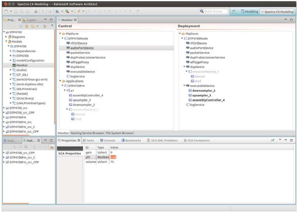
![Spectra CX Modeling -- Rational® Software Architect\nQuick Access\nModeling\nSpectra CX Modeling\nProj...\nLayers\nMonitor\nControl\nPlatform\nDTP4700Node\nrfCtrlDevice\naudioPortDevice\npacketService\ndspProbeListenerService\nwffpgaProxy\ndspDevice\nexecutableDevice\nlogService\nApplications\nDTP4700Fm\na1\nassemblyController_4\nupsampler_3\ndownsampler_2\nresourceFactory_1\ndemod\nmod\nDeployment\nPlatform\nDTP4700Node\nrfCtrlDevice\naudioPortDevice\npacketService\ndspProbeListenerService\nwffpgaProxy\ndspDevice\nresourceFactory_1\ndemod\nmod\nexecutableDevice\ndownsampler_2\nupsampler_3\nassemblyController_4\nlogService\nMonitor | Naming Service Browser | File System Browser |\nOut...\nMake...\nProperties | Tasks | Console | Bookmarks | SCA XML Problems | SCA Connectors\nID | Type | Value\ngain | Ushort | 0\nptt | Boolean | int.\nvolume | Ushort | 75](.spectra-dtp4700-userguide/2e3663ffdb611f415fe6a355a01a76c55f7f8f5c7ea0b3eaa1b5b53f0f9af8fd.jpg)

Figure 57 Setting the ptt property

To disable transmission of FM audio:

Step 1: Disable ptt.

Select the audioPortDevice in the Control pane and switch to the Properties view, then select the SCA Properties tab. Select the ptt property and set the value to false.

# 8.2.10.6 Stopping the FM Waveform

To stop the running application instance:

Step 1: In the Control pane, right-click on the instance a1 of the application DTP4700Fm.

Step 2: Choose Stop from the context menu.
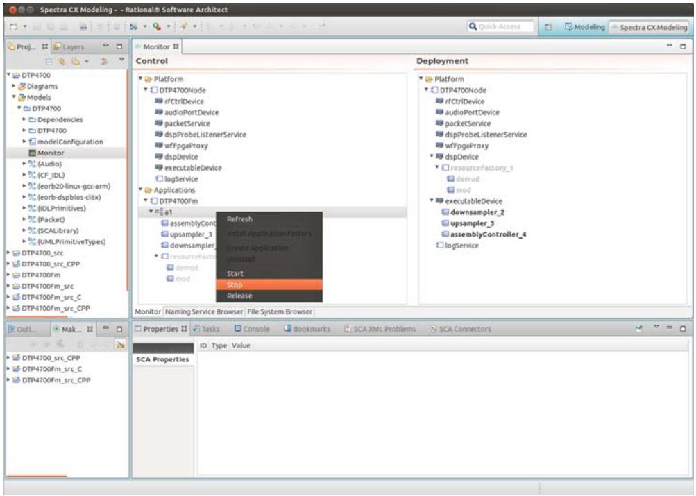
![Spectra CX Modeling - Rational® Software Architrect\nQuick Access\nModeling\nSpectra CX Modeling\nProj...\nLayers\nDTP4700\nDiagrams\nModels\nDTP4700\nDependencies\nDTP4700\nmodelConfiguration\nMonitor\n(Audio)\n(CF_IDL)\n(eorb20-linux-gcc-arm)\n(eorb-dspbios-c16x)\n(IDLPrimitives)\n(Packet)\n(SCALibrary)\n(UMLPrimitiveTypes)\nDTP4700_src\nDTP4700_src_CPP\nDTP4700Fm\nDTP4700Fm_src_C\nDTP4700Fm_src_CPP\nDTP4700_src_CPP\nDTP4700Fm_src_C\nDTP4700Fm_src_CPP\nMonitor | Naming Service Browser | File System Browser\nDisplay\nPlatform\nDTP4700Node\nrfCtrlDevice\naudioPortDevice\npacketService\ndspProbeListenerService\nwffpgaProxy\ndspDevice\nexecutableDevice\nlogService\nApplications\nDTP4700fm\na1\nassemblyCont\nupsampler_3\ndownsamplet\nresourceFacto\ndemod\nmod\nRefresh\nInstall Application Factory\nCreate Application\nUninstall\nStart\nStop\nRelease\nPlatform\nDTP4700Node\nrfCtrlDevice\naudioPortDevice\npacketService\ndspProbeListenerService\nwffpgaProxy\ndspDevice\nResourceFactory_1\ndemod\nmod\nexecuteableDevice\ndownsamplet_2\nupsampler_3\nassemblyController_4\nlogService\nMonitor | Naming Service Browser | File System Browser\nProperties | Tasks | Console | Bookmarks | SCA XML Problems | SCA Connectors\nID: Type Value\nSCA Properties](.spectra-dtp4700-userguide/9d0dffeff94eca740f8595d5bf94cd38c5aa19d13b16af62172bc412c54c10f7.jpg)

Figure 58 Stopping a running application instance

Stopping the application halts the processing of audio samples.

# 8.2.10.7 Releasing the FM Waveform

To release the resources of the stopped application instance:

Step 1: In the Control pane, right-click on the instance a1 of the application DTP4700Fm.

Step 2: Choose Release from the context menu.

A successful release will tear down the application instance and it will disappear from the Application folder in the Control pane (see Figure 59 and Figure 60). The relevant components also disappear from the Deployment pane.
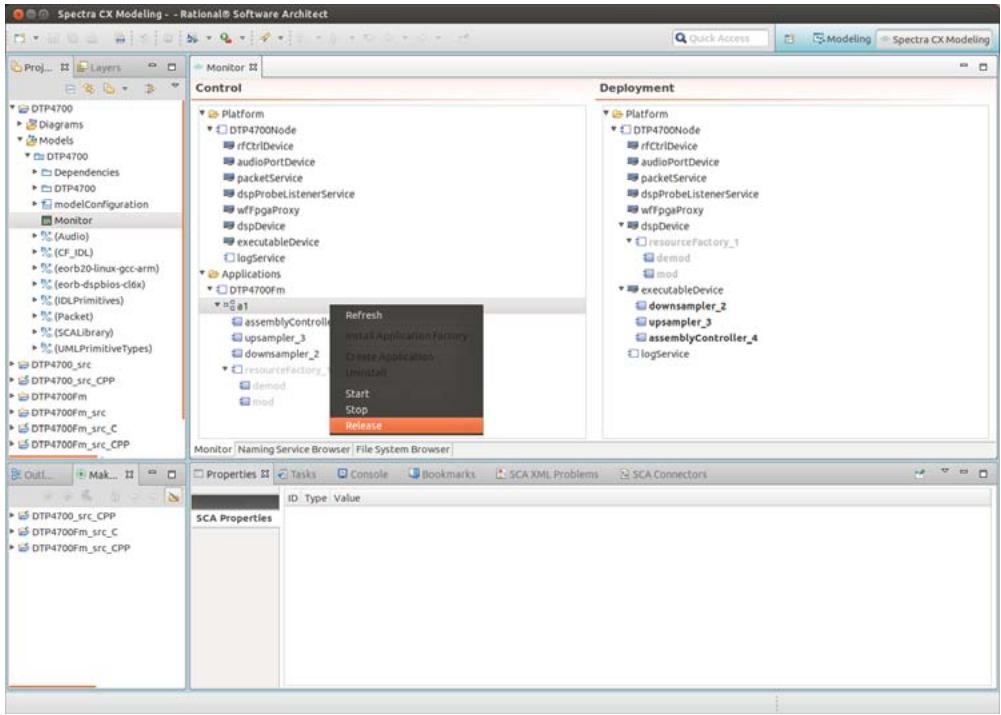
![Spectra CX Modeling -- Rational® Software ArchRect\nQuick Access\nModeling\nSpectra CX Modeling\nProj...\nLayers\nDTP4700\nDiagrams\nModels\nDTP4700\nDependencies\nDTP4700\nmodelConfiguration\nMonitor\n(Audio)\n(CF_IDL)\n(eorb20-linux-gcc-arm)\n(eorb-dspbios-c16x)\n(IDLPrimitives)\n(Packet)\n(SCALibrary)\n(UMLPrimitiveTypes)\nDTP4700_src\nDTP4700_src_CPP\nDTP4700Fm\nDTP4700Fm_src_C\nDTP4700Fm_src_CPP\nMonitor | Naming Service Browser | File System Browser\nOut...\nMak...\nDTP4700_src_CPP\nDTP4700Fm_src_C\nDTP4700Fm_src_CPP\nDTP4700Fm_src/\nDTP4700Fm_src/\nDTP4700Fm_src/\nDTP4700Fm_src/\nDTP4700Fm_src/\nDTP4700Fm_src/\nDTP4700Fm_src/\nDTP4700Fm_src/\nDTP4700Fm_src/\nDTP4700Fm_src/\nDTP4700Fm_src/1\nDTP4700Fm_src/2\nDTP4700Fm_src/3\nDTP4700Fm_src/4\nDTP4700Fm_src/5\nDTP4700Fm_src/6\nDTP4700Fm_src/7\nDTP4700Fm_src/8\nDTP4700Fm_src/9\nDTP4700Fm_src/10\nDTP4700Fm_src/11\nDTP4700Fm_src/12\nDTP4700Fm_src/13\nDTP4700Fm_src/14\nDTP4700Fm_src/15\nDTP4700Fm_src/16\nDTP4700Fm_src/17\nDTP4700Fm_src/18\nDTP4700Fm_src/19\nDTP4700Fm_src/20\nDTP4700Fm_src/21\nDTP4700Fm_src/22\nDTP4700Fm_src/23\nDTP4700Fm_src/24\nDTP4700Fm_src/25\nDTP4700Fm_src/26\nDTP4700Fm_src/27\nDTP4700Fm_src/28\nDTP4700Fm_src/29\nDTP4700Fm_src/30\nDTP4700Fm_src/31\nDTP4700Fm_src/32\nDTP4700Fm_src/33\nDTP4700Fm_src/34\nDTP4700Fm_src/35\nDTP4700Fm_src/36\nDTP4700Fm_src/37\nDTP4700Fm_src/38\nDTP4700Fm_src/39\nDTP4700Fm_src/40\nDTP4700Fm_src/41\nDTP4700Fm_src/42\nDTP4700Fm_src/43\nDTP4700Fm_src/44\nDTP4700Fm_src/45\nDTP4700Fm_src/46\nDTP4700Fm_src/47\nDTP4700Fm_src/48\nDTP4700Fm_src/49\nDTP4700Fm_src/50\nDTP4700Fm_src/51\nDTP4700Fm_src/52\nDTP4700Fm_src/53\nDTP4700Fm_src/54\nDTP4700Fm_src/55\nDTP4700Fm_src/56\nDTP4700Fm_src/57\nDTP4700Fm_src/58\nDTP4700Fm_src/59\nDTP4700Fm_src/60\nDTP4700Fm_src/61\nDTP4700Fm_src/62\nDTP4700Fm_src/63\nDTP4700Fm_src/64\nDTP4700Fm_src/65\nDTP4700Fm_src/66\nDTP4700Fm_src/67\nDTP4700Fm_src/68\nDTP4700Fm_src/69\nDTP4700Fm_src/70\nDTP4700Fm_src/71\nDTP4700Fm_src/72\nDTP4700Fm_src/73\nDTP4700Fm_src/74\nDTP4700Fm_src/75\nDTP4700Fm_src/76\nDTP4700Fm_src/77\nDTP4700Fm_src/78\nDTP4700Fm_src/79\nDTP4700Fm_src/80\nDTP4700Fm_src/81\nDTP4700Fm_src/82\nDTP4700Fm_src/83\nDTP4700Fm_src/84\nDTP4700Fm_src/85\nDTP4700Fm_src/86\nDTP4700Fm_src/87\nDTP4700Fm_src/88\nDTP4700Fm_src/89\nDTP4700Fm_src/90\nDTP4700Fm_src/91\nDTP4700Fm_src/92\nDTP4700Fm_src/93\nDTP4700Fm_src/94\nDTP470OFSRCPCPCPCPCPCPCPCPCPCPCPCPCPCPCPCPCPCPCPCPCPCPCPCPCPCPCPCPCPCPCPCPCPCPCPCPCPCPCPCPCPCPCPCPCPCPCPCPCPCPCPCPCPCPCPCPCPCPCPCPCPCPCPCPCPCPCPCPCPCPCPCPCPCPCPCPCPCPCPCPCPCPCPCPCPCPCPCPCPCPCPCPCPCPCPCPCPCPCPCPCPCCPPCCPPCCPPCCPPCCPPCCPPCCPPCCPPCCPPCCPPCCPPCCPPCCPPCCPPCCPPCCPPCCPPCCPPCCPPCCPPCCPPCCPPCCPPCCPPCCPPCCPPCCPPCCPPCCPPCCPPCCPPCCPPCCPPCCPPCCPPCCPPCCPPCCPPCCPPCCPPCCPPCCPPCCPPCCPPCCPPCCPPCCPPCCPPCCPPCCPPCCPCCPPCCPPCCPPCCPPCCPPCCPPCCPPCCPPCCPPCCPPCCPPCCPPCCPPCCPPCCPPCCPPCCPPCCPPCCPPCCPPCCPPCCPPCCPPCCPPCCPPCCPPCCPPCCPPCCPPCCPPCCPPCCPPCCPPCCPPCCPPCCPPCCPPCCPPCCPPCCPPCCPPCCPPCCPPCCPPCCPPCCPPCCTPSCCA PROPERTIES ID: Type Value](.spectra-dtp4700-userguide/5e3b55135a5d959acaf6ab36b4747b05774cf187e63c3ca2bdbc408a715efd83.jpg)

Figure 59 Releasing a stopped application instance
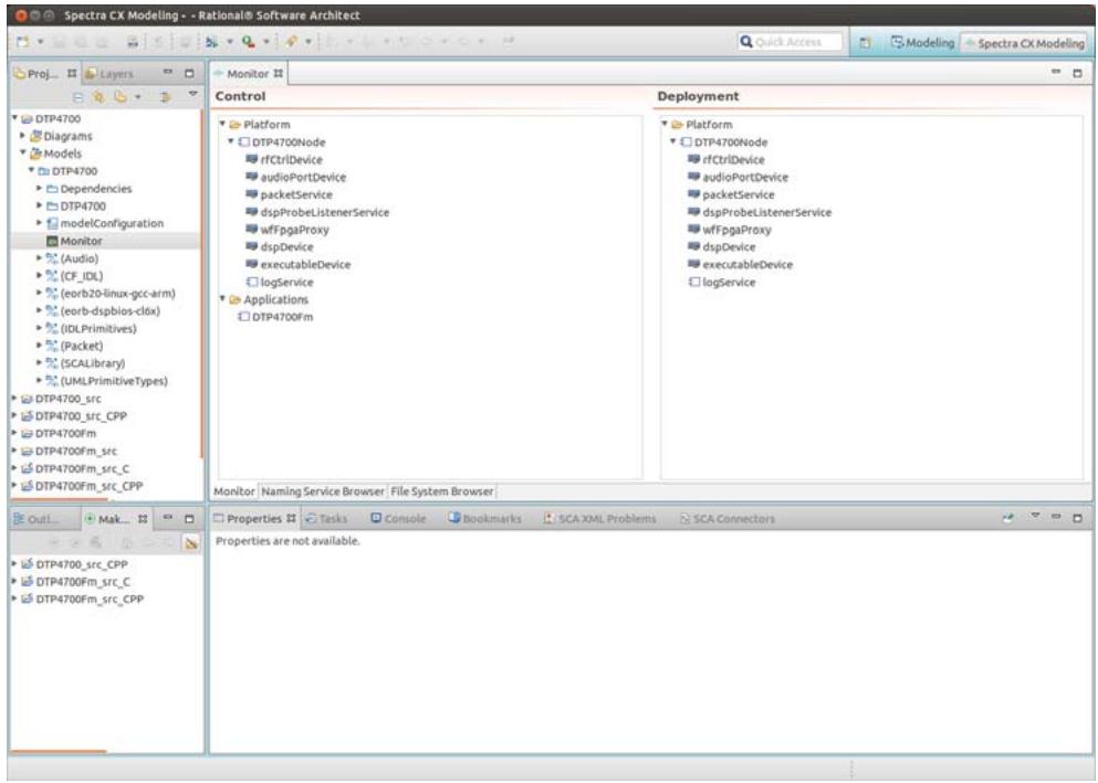
![Spectra CX Modeling -- Rational® Software Architect\nQuick Access\nModeling\nSpectra CX Modeling\nProj...\nLayers\nMonitor\nControl\nDeployment\nDTP4700\nDTP4700Node\nrfCtrlDevice\naudioPortDevice\npacketService\ndspProbeListenerService\nwffpgaProxy\ndspDevice\nexecutableDevice\nlogService\nApplications\nDTP4700Fm\nPlatform\nDTP4700Node\nrfCtrlDevice\naudioPortDevice\npacketService\ndspProbeListenerService\nwffpgaProxy\ndspDevice\nexecutableDevice\nlogService\nOut...\nMake...\nDTP4700_src_CPP\nDTP4700Fm_src_C\nDTP4700Fm_src_CPP\nPlatform\nDTP4700Node\nrfCtrlDevice\naudioPortDevice\npacketService\ndspProbeListenerService\nwffpgaProxy\ndspDevice\nexecutableDevice\nlogService\nProperties are not available.\nDTP4700Fm_src_C\nDTP4700Fm_src_CPP](.spectra-dtp4700-userguide/00b0fe1c705dfce98125fb5fb5980630df161805a43df91876e11810c727441e.jpg)

Figure 60 Application instance successfully released

# 8.2.10.8 Uninstalling the FM Waveform

To uninstall the FM Waveform application:

Step 1: In the Control pane, right-click on the DTP4700Fm application.

Step 2: Choose Uninstall from the context menu.

Successfully uninstalling the application removes the waveform from the DTP4700 platform (see Figure 61 and Figure 62).
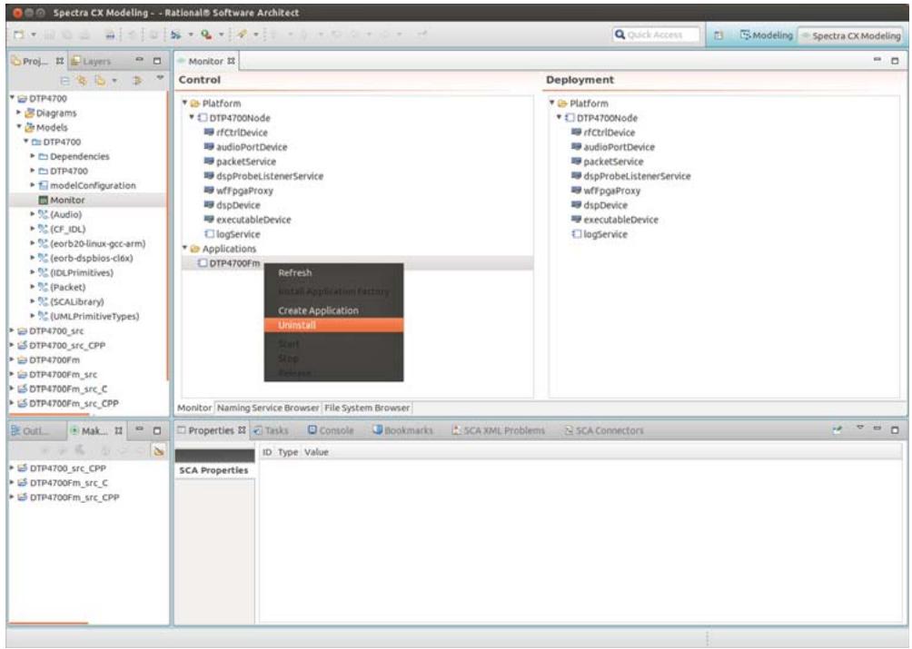
![Spectra CX Modeling - Rational® Software Architrect\nQuick Access\nModeling\nSpectra CX Modeling\nProj...\nLayers\nMonitor\nControl\nPlatform\nDTP4700Node\nrfCtrlDevice\naudioPortDevice\npacketService\ndspProbeListenerService\nwffpgaProxy\ndspDevice\nexecutableDevice\nlogService\nApplications\nDTP4700Fm\nRefresh\nInstall Application factory\nCreate Application\nUninstall\nStart\nStop\nRelease\nDeployment\nPlatform\nDTP4700Node\nrfCtrlDevice\naudioPortDevice\npacketService\ndspProbeListenerService\nwffpgaProxy\ndspDevice\nexecutableDevice\nlogService\nMonitor | Naming Service Browser | File System Browser\nOut1...\nMak...\nDTP4700_src_CPP\nDTP4700Fm_src_C\nDTP4700Fm_src_CPP\nDTP4700_src_CPP\nDTP4700Fm_src_C\nDTP4700Fm_src_CPP\nProperties\nTasks Console Bookmarks SCA XML Problems SCA Connectors\nID: Type Value\nSCA Properties](.spectra-dtp4700-userguide/dc51631f53365724546d9803a61f97c6ea60141975b4f6d463236ab68c5cc879.jpg)

Figure 61 Uninstalling an application
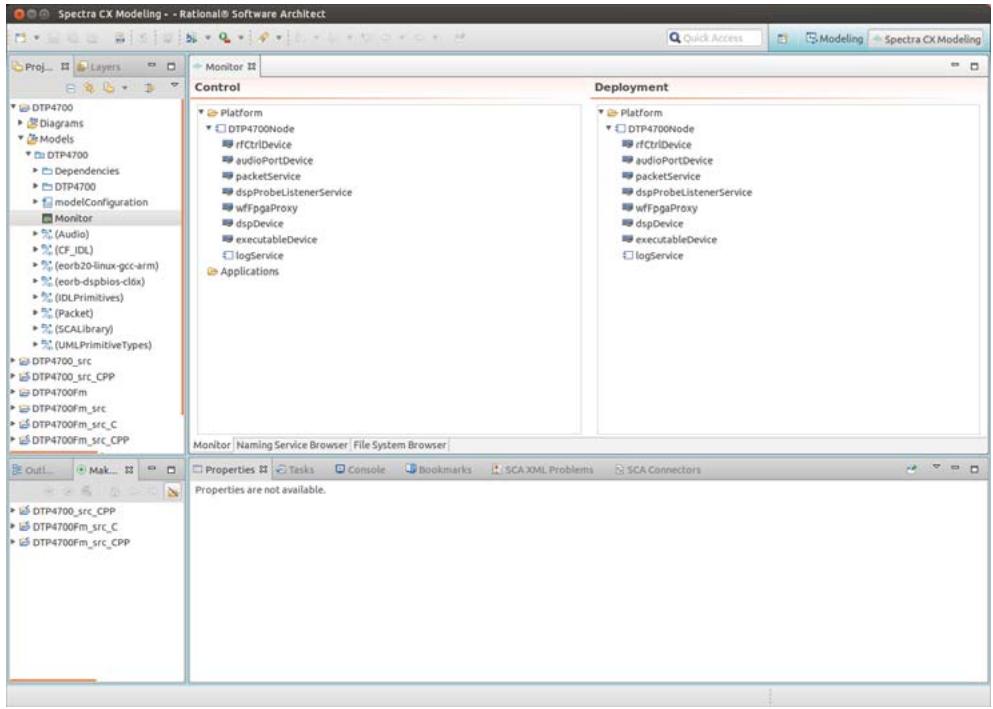
![Spectra CX Modeling -- Rational® Software Architect\nQuick Access\nModeling\nSpectra CX Modeling\nProj...\nLayers\nMonitor\nControl\nDeployment\nDTP4700\nDTP4700Node\nrfCtrlDevice\naudioPortDevice\npacketService\ndspProbeListenerService\nwffpgaProxy\ndspDevice\nexecutableDevice\nlogService\nApplications\nPlatform\nDTP4700Node\nrfCtrlDevice\naudioPortDevice\npacketService\ndspProbeListenerService\nwffpgaProxy\ndspDevice\nexecutableDevice\nlogService\nMonitor | Naming Service Browser | File System Browser |\nOut...\nMake...\nDTP4700_src_CPP\nDTP4700Fm_src_C\nDTP4700Fm_src_CPP\nProperties are not available.\nProperties](.spectra-dtp4700-userguide/90b8301ffa9c47eed241953f4b96b837c8b0398f6f9938c4f45ff90d6058579c.jpg)

Figure 62 Application successfully uninstalled

# 8.3 Running the FM Tutorial using cfadmin

The CF platform comes with a console-based utility, cfadmin, to control the lifecycle of SCA waveforms. cfadmin runs on the Thunder target so that it can interact with all application and platform components.

i This section only gives an example of how to start cfadmin; please refer to the Spectra CF User Guide for a full description of cfadmin, and for step-by-step instructions showing how to use it to install, create, start, stop, release and uninstall waveforms.

# 8.3.1 Starting cfadmin

Step 1: Open a serial console (GtkTerm, telnet or SSH) session on the Thunder system and log in as root.

Step 2: Start cfadmin, passing it the reference of the Naming Service started by the DomainManager:

```txt
cfadmin -ORBInitRef
NameService=corbaloc:iiop:1.1@172.31.255.1:2809/NameService
-NAME_BINDING /DTP4700Domain/DomainManager
```

cfadmin will display a text menu of options to display and manage various aspects of the domain. Entering ‘V’ at the menu prompt will display all components that belong to the domain, including application factories, applications (and their resources), device managers, devices and services.
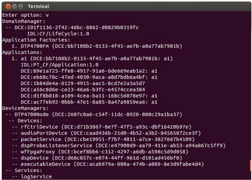
![Enter option: v\nDomainManager:\n-- DCE:591f1136-2f42-46bc-8862-d0829b0319fc\nIDL:CF/LifeCycle:1.0\nApplication Factories:\n1. DTP4700Fm (DCE:bb7108b2-0133-4f45-ae7b-a0a77ab7981b)\nApplications:\n1. a1 (DCE:bb7108b2-0133-4f45-ae7b-a0a77ab7981b: a1)\nIDL:PT_CF/Application:1.0\nDCE:89e1a725-ffe8-4917-91a6-6de669eab1a2: a1\nDCE:eb68c78c-47ed-4030-9aca-a0d7bdb6a4bf: a1\nDCE:1b84de4a-6129-4915-aac5-8cd7e2a3a5d7\nDCE:a56c8d6e-ce23-46a6-b3fc-e4574cce384\nDCE:d1f8b818-a109-4cea-ba11-168c56078e97: a1\nDCE:ac77eb92-0bbb-47e1-8a05-8a47a9859ea6: a1\nDeviceManagers:\n-- DTP4700Node (DCE:2607c0a6-c54f-11dc-8920-000c29a1ba37)\n-- Devices:\n-- rfCtrlDevice (DCE:d71b3867-0e7f-47f5-a93c-dbf16420b97e)\n-- audioPortDevice (DCE:caad436b-21d0-4b52-a3b2-84565872ce3f)\n-- packetService (DCE:cbe19951-f7b7-4011-a7ce-3827667b4109)\n-- dspProbeListenerService (DCE:e47900d9-aa79-411e-ab53-a94a867c5ff9)\n-- wfFpgaProxy (DCE:bcef8bb6-c312-4297-a6db-a598c5d9d058)\n-- dspDevice (DCE:d68c857c-e074-44ff-961d-d101ad456bf0)\n-- executableDevice (DCE:acab979a-800a-474b-a089-8e3d9fabe4d4)\n-- Services:\n-- logService](.spectra-dtp4700-userguide/5645cfb0aa1eae6b185854f93f15352091f48ced659cba89d30a514ec2092b75.jpg)

Figure 63 cfadmin output confirming application has been created

In Figure 63 above, the application a1 shows that it is comprised of six resources. cfadmin only displays the instantiation UUIDs of the components as defined in the SAD XML descriptor. An annotated listing of the application components is shown below:

```txt
DCE:89e1a725-ffe8-4917-91a6-6de669eab1a2: a1 [downsampler]
DCE:eb68c78c-47ed-4030-9aca-a0d7bdb6a4bf: a1 [upsampler]
DCE:1b84de4a-6129-4915-aac5-8cd7e2a3a5d7 [demod]
DCE:a56c8d6e-ce23-46a6-b3fc-e4574ccea384 [mod]
DCE:d1f8b818-a109-4cea-ba11-168c56078e97: a1 [resourceFactory]
DCE:ac77eb92-0bbb-47e1-8a05-8a47a9859ea6: a1 [assemblyController]
```
[🔗 Link to the original document](.spectra-dtp4700-userguide/spectra-dtp4700-userguide.pdf)
