# Spectra IP Core Orb

Version 2.3

# User Guide

![-commerce\nOS](.spectra-ico-userguide/889d3e52d0ca750027df49077c864e6a9c69dec78f3862552c61ec87c03043a6.jpg)

# IP Core Orb

# USER GUIDE

![The image displays a simple icon resembling an envelope. It features a red triangle at the top, sitting directly above a blue rectangle. Inside the blue rectangle is a white inverted triangle. The background is white.](.spectra-ico-userguide/c3f433666ed2b8591caf91ce74af025f870df19bf3b005e34110fa6702233c50.jpg)

PRISMTECH

# Copyright Notice

© 2013 PrismTech Limited. All rights reserved.

This document may be reproduced in whole but not in part.

The information contained in this document is subject to change without notice and is made available in good faith without liability on the part of PrismTech Limited or PrismTech Corporation.

All trademarks acknowledged.

# CONTENTS

# Table of Contents

# Preface

About the User Guide. . . . . . 3

Contacts . . . .

# Introduction

# Chapter 1 Introduction 7

1.1 Features . . .

1.2 Overview . . . .

# Installation

# Chapter 2 Installation 1 3

2.1 Pre-requisites . . . . . . 13

2.2 Supported Platforms . . . . . . 13

2.3 Licensing. . . . . . . 13

2.4 Installation of ICO. . . . . . . . 14

2.5 Installing ICO Prerequisites . . . . . . . . 14

2.5.1 Installing the Java runtime . 14

2.5.2 Installing Python . . . 14

2.5.3 Installing SCons . . . 15

2.5.4 Environment Settings . . . 15

2.5.4.1 Specifying the ICOHOME directory. . . 15

2.5.4.2 Changing the JRE location 15

2.5.4.3 Updating the system path 16

# Architecture

# Chapter 3 Architecture 19

3.1 Arbitration . . . . . 20

3.2 Bridges, Transports and FIFOs . . . . . . . . 20

3.3 ICO Top Level Entity . . . . . . . 21

3.3.1 Servants and Clients . . 21

3.4 Connection Ids . . . . . . . 22

3.5 Multiple Bridges (Transports) . . . . . . . . 23

# IDL to VHDL Mapping

# Chapter 4 IDL to VHDL Mapping 27

4.1 The BIOP Protocol . . . . . . . 27

4.1.1 BIOP Two-Way Request Message Format . 27

4.1.2 BIOP One-Way Request Message Format . . . 28

4.1.3 BIOP Reply Message Format. . . 28
4.1.4 BIOP Exception Message Format 29
4.2 Mapping from IDL to VHDL . . . . . . . . 29
4.2.1 Basic Data Types . 29
4.2.2 Constructed Data Types . . . . 30
4.2.3 Module/Interface Mapping. . . . 30
4.2.4 Operation Mapping. . . . . 31
4.2.5 Exception Mapping . . . 32
4.2.6 Attribute Mapping . . 32
4.2.7 Const Mapping . . . . 32
4.2.8 Any Mapping . . . . 32
4.3 Example Mapping . . . . . . . . 32

# Developing Applications

# Chapter 5 Developing Applications 3 7

5.1 Structured VHDL . . . . . . 37
5.2 Operation Abstraction . . . . . . . 38
5.3 The IDL to VHDL Compiler . . . . . . . 40
5.3.1 Running the IDL to VHDL compiler . . . 41
5.4 Limitations . . . . . . 45
5.5 Compiler Output . . . . . . . 45
5.6 Generated Client/Server Entity Signals . . . . . . . 47
5.7 User Input/Output . . . . . . . . 48
5.7.1 User I/O VHDL records . . . 48
5.7.2 GPIO port entries . 49
5.8 The Perfect Hash Generator Utility. . . . . . . . 49
5.9 ICO Development Lifecycle . . . . . . . . 50
5.9.1 Create the IDL . 51
5.9.2 Compile the IDL. . . 51
5.9.3 Integrate User Logic . . . . 52
5.9.4 Obtaining the ICO servant IOR . 55
5.10 ICO Development Examples . . . . . . . 56
5.10.1 Increment by One Example . . 56
5.10.1.1 Design . . . . 56
5.10.1.2 Implementing The Server . . 57
5.10.1.3 Implementing the Client 59
5.10.1.4 Simulation . . . 59
5.10.2 LEDs Example . 60
5.11 Generating Sequences . . . . . . 61
5.12 Using the CORBA Any Type . . . . . . . . 62

# Transports

# Chapter 6 Transports 6 7

6.1 Introduction . . . . 67

6.2 Transport Connections . . . . . . . 68
6.2.1 Receive (Rx) Interface 71
6.2.2 Transmit (Tx) Interface 72
6.3 Packet Based Transports . . . . . . . 73
6.3.1 Receiving Packets. . . . 74
6.3.2 Transmitting Packets 74
6.3.3 Transport Connection Identification. . 75
6.3.4 Outgoing Requests . . . . 76
6.4 Supporting Multiple End Points . . . . . . . . 76
6.5 Dynamic Endpoints . . . . . . . 77

# List of Figures

Figure 1 ICO High-level Architecture . . . . . . . 19

Figure 2 ICO Receive and Transmit Bridges . . . . . . . 20

Figure 3 Servants and Clients . . . . . . 21

Figure 4 Connection IDs . . . . . . 22

Figure 5 Multiple Bridges . . . . . . . 23

Figure 6 Generic Two-process Model . . . . . . . . 37

Figure 7 Perfect Hash Timing . . . . . . . 49

Figure 8 ICO Development Lifecycle . . . . . . 51

Figure 9 Servant Finite State Machine . . . . . . . 52

Figure 10 Client Finite State Machine . . . . . . . 53

Figure 11 Bus To Servant Write . . . . . . 54

Figure 12 Bus Write Timing . . . . . . 54

Figure 13 Servant To Bus Write . . . . . . . . 55

Figure 14 Connections in ICO . . . . . . . . 68

Figure 15 ICO Incoming Data . . . . . . . . 72

Figure 16 ICO Outgoing Data . . . . . . . . 73

Figure 17 Transmit Flow Control . . . . . . . 73

Figure 18 Receiving Packets . . . . . . . 74

Figure 19 Transmitting Packets . . . . . . . 75

Figure 20 Receiving Connection IDs . . . . . . . . 75

Figure 21 Transmitting Connection IDs . . . . . . . . 76

Figure 22 Object Key Timing . . . . . . . . . 76

# P re f a c e

# About the User Guide

This User Guide provides instructions and information needed to use Spectra IP Core Orb.

# Intended Audience

This User Guide is for developers who use Spectra IP Core Orb (referred to as ICO) in developing applications based on CORBA and the Software Communications Architecture (SCA).

# Organisation

The User Guide is organised as follows:

Chapter 1, Introduction, gives a general description of the features and functions of the Spectra IP Core Orb.

Chapter 2, Installation, describes the process of installing ICO on both Windows and Linux platforms.

Chapter 3, Architecture, describes the concepts behind ICO.

Chapter 4, IDL to VHDL Mapping, explains the BIOP (Bus Inter-Operability Protocol) and the way IDL is mapped to VHDL in ICO.

Chapter 5, Developing Applications, describes how ICO is used to implement CORBA interfaces (clients and servers).

Chapter 6, Transports, gives detailed descriptions of the use of protocols such as TCP and UDP with ICO interfaces.

# Conventions

The conventions listed below are used to guide and assist the reader in understanding this User Guide.

![The image displays a standard warning sign in the shape of a red triangle with a white background. Inside the triangle is a black exclamation point with a downward-pointing arrow positioned directly below it.](.spectra-ico-userguide/db880d9f54d0268a17080ce599fac4982d855cb398bc122d08f37e2e802fc472.jpg)

i

WIN

UNIX

Linux

Item of special significance or where caution needs to be taken.

Item contains helpful hint or special information.

Information applies to Windows (e.g. XP, 2003, Windows 7) only.

Information applies to Unix-based systems (e.g. Solaris) only.

Information applies to Linux-based systems (e.g. Ubuntu) only.

Hypertext links are shown as blue italic underlined.

On-Line (PDF) versions of this document: Cross-references such as ‘see Contacts on page 4’ act as hypertext links: click on the reference to jump to the item.

% Commands or input which the user enters on the command line of a computer terminal

Courier fonts indicate programming code, commands, file names, and values stored in variables and fields.

Extended code fragments and log file contents are shown in shaded boxes:

```javascript
NameComponent newName[] = new NameComponent[1]; // set id field to "example" and kind field to an empty string newName[0] = new NameComponent ("example", "");
```

Italics and Italic Bold are used to indicate new terms, or emphasise an item.

Sans-serif and Sans-serif Bold are used to indicate components of a Graphical User Interface (GUI) or an Integrated Development Environment (IDE), such as a Cancel button, and sequences of actions, such as selecting File > Save from a menu.

The names of keyboard keys are shown in SANS-SERIF SMALL CAPS, e.g. RETURN. (Combinations of keys to be pressed simultaneously have their names joined with a ‘plus’ sign: CTRL+C and CTRL+ALT+DELETE.) Names of navigation keys and keys on the numeric pad are spelled out (e.g. LEFT, DOWN, PLUS, MINUS).

Angle brackets &lt; &gt; enclosing code, command arguments, and similar types of text strings, are used to indicate ‘placeholders’ to be replaced by user-supplied values.

Step 1: One of several steps required to complete a task.

# Contacts

PrismTech can be reached at the following contact points for information and technical support.

<table><tr><td>USA Corporate Headquarters</td><td>European Head Office</td></tr><tr><td>PrismTech Corporation</td><td>PrismTech Limited</td></tr><tr><td>400 TradeCenter</td><td>PrismTech House</td></tr><tr><td>Suite 5900</td><td>5th Avenue Business Park</td></tr><tr><td>Woburn, MA</td><td>Gateshead</td></tr><tr><td>01801</td><td>NE11 0NG</td></tr><tr><td>USA</td><td>UK</td></tr><tr><td>Tel: +1 781 569 5819</td><td>Tel: +44 (0)191 497 9900</td></tr><tr><td></td><td>Fax: +44 (0)191 497 9901</td></tr></table>

<table><tr><td>Web:</td><td>http://www.prismtech.com</td></tr><tr><td>Technical questions:</td><td>crc@prismtech.com (Customer Response Center)</td></tr><tr><td>Sales enquiries:</td><td>sales@prismtech.com</td></tr></table>

# INTRODUCTION

# CHAPTER

# 1 Introduction

Spectra IP Core ORB (ICO) is part of the PrismTech family of products for Software Defined Radio (SDR) applications. It provides a highly integrated and innovative VLSI solution for implementing the Common Object Request Broker Architecture (CORBA) and Software Communications Architecture (SCA) protocols on silicon devices. Hardware elements of a system may now be made CORBA compliant and reap the benefits of software portability. In addition to supporting general purpose CORBA communications, ICO is being tightly integrated into PrismTech’s Spectra tool suite for SDR. This brings the portability of the SCA onto silicon devices and eliminates the need for custom proxies and Hardware Abstraction Layers (HAL).

# 1.1 Features

• Supports GIOP version 1.0 protocol
• Processes incoming and outgoing CORBA requests:
- One-way operations
- Two-way operations

• Support for CORBA clients and servers:

- Servants implemented on FPGA in VHDL
- Clients can be internal to the FPGA written in VHDL or external to the FPGA (e.g. on a GPP or DSP) implemented by a conventional software application
- No arbitrary restriction on the number of clients and servants that can be supported on the FPGA

• IDL compiler support:

\- Supports the IDL to VHDL language mapping and will auto-generate VHDL clients and servers, allowing ICO to be easily connected to servants implementing waveform logic

\- Based on CORBA 3 grammar, supporting a subset of data types and constructs:

```txt
- Basic data types:
  - Char, Octet
  - Boolean
  - Short, Unsigned Short
  - Long, Unsigned Long
  - Long Long, Unsigned Long Long
  - String

- Enumerated types
- CORBA Object type
- Constructed data types:
  - Struct
  - Sequence
  - Array

- CORBA Any containing Basic data types
- CORBA exceptions support:
  - User exceptions
  - System exceptions
```

• Pluggable and open transport interface allows user-defined custom transports to be plugged into ICO
• Written in pure VHDL to maximise portability across FPGA devices.

# 1.2 Overview

ICO v2 is a second generation hardware implementation of a CORBA ORB. It supports a general subset of CORBA functions required to support the SCA architecture and the functions that are typically implemented in hardware. While ICO may be used to provide SCA compatibility, it is primarily a CORBA core and may also be used in pure CORBA applications with no SCA requirements. ICO eliminates the need to develop custom proxies on General Purpose Processors (GPP) and Digital Signal Processors (DSP) that simply serve to establish communication to waveform objects residing within an FPGA (Field Programmable Gate Array). These proxies, sometimes referred to as Hardware Abstraction Layers (HAL), are used when designing to Software Defined Radio (SDR) architectures such as the SCA and are meant to increase portability and re-use. However, in practice, the proxies tend to increase latency, reduce throughput, and lower re-use. ICO further eliminates the need to embed general purpose processing cores into an FPGA in order to offer software ORB capability. Although a viable approach, this approach tends to require significant gate count and memory utilization and generally these processing cores cannot be clocked fast enough to deal with the ever-increasing performance requirements of SDR applications.

The ICO development environment consists of:

• the ICO IP core
• IDL to VHDL Compiler
• A number of board-specific example transports

The ICO IP core is responsible for implementing the transfer syntax used in CORBA messages. The core decodes the incoming GIOP octet stream and extracts header and data fields while discarding padding. Byte order conversion is performed on all incoming data based on information in the GIOP message header. In the incoming direction, the core performs object key and operation name demultiplexing to determine which object and function should receive the data in the GIOP message. Message data is then extracted for transfer to the appropriate logic. The ICO core generates a reply message if a response is expected. The core obtains data for the reply from the servant. It then populates the header field and aligns the data. When a reply message has been built, the ICO core transfers the data to the outside world via a FIFO-like interface. A pair of FIFOs are used to process incoming (request) and outgoing (reply) messages concurrently.

The IDL to VHDL complier is a software tool responsible for generating the configuration parameters needed by the ICO core to perform object key and operation name demultiplexing and data routing to the appropriate application logic. The compiler is responsible for assigning handshake signals between ICO and embedded client and server objects.

The hardware developer treats ICO as any other IP interface core. The core can be instantiated in the HDL capture of the FPGA design between the native application logic and the embedded transport logic. The transport side of the core appears as a typical FIFO interface. The application side of the core has a simple and open interface to communicate with the application logic.

ICO communicates with a software ORB over the local transport media. In many cases the local transport will be a low level system bus that does not support high level communication protocols. This situation requires that the software ORB make use of pluggable transport interface such as the OMG Extensible Transport Framework (ETF). A custom transport plug-in must be created to transfer GIOP messages from the software ORB to the local transport. This situation is not unique to ICO, but would be required for any ORB that does not choose to use IIOP (GIOP over TCP/IP) by default.

# INSTALLATION

# CHAPTER

# 2 Installation

# 2.1 Pre-requisites

The following are required for building and installing the ICO ORB:

• PrismTech ICO license for the IDL to VHDL compiler.
• Altera Quartus II v10.1 (or later) FPGA development environment and Modelsim Altera v6.6 simulator.
• Xilinx ISE v14.2 (or later) FPGA development environment (including ISim simulator).
• Java (JDK/JRE) Version 1.6.
• The SCons software build system.
• A software ORB for testing a simulated ICO on the host development system. Spectra e\*ORB C Edition Version 1.6 is recommended.

Users must have a working knowledge of the hardware simulator and the FPGA development tools they are using.

# 2.2 Supported Platforms

The ICO IDL to VHDL compiler supports Windows and Linux host development platforms. ICO is written in portable VHDL, and as such is not tied to any one IP. The list of supported target platforms is reviewed and extended regularly. Please contact PrismTech for the latest information on your selected platform.

# 2.3 Licensing

The user must obtain and install a valid license file in order to run the IDL to VHDL compiler. Permanent and evaluation licenses can be obtained from PrismTech. To install the license file, copy the license file, named license.lic, into the etc subdirectory under the ICO installation directory. To request a license key from PrismTech the host id of the target system is required. This can be obtained with the following command:

% rlmutil rlmhostid ether

# 2.4 Installation of ICO

The ICO distribution is supplied in a gzip tar file for Linux or zip file for Windows. Extract the contents of the ICO package to the directory where you wish the product to be installed. ICO can be uninstalled by deleting the installation directory.

The ICO installation contains the directories shown in Table 1.

Table 1 ICO directories

<table><tr><td>Directory</td><td>Description</td></tr><tr><td></td><td>Top-level directory</td></tr><tr><td></td><td>Executables for the IDL to VHDL compiler</td></tr><tr><td></td><td>ICO release information and license</td></tr><tr><td></td><td>ICO core source files</td></tr><tr><td></td><td>Source files for transports</td></tr><tr><td></td><td>Code libraries</td></tr><tr><td></td><td>Example code</td></tr><tr><td></td><td>Documentation and release notes</td></tr></table>

Configuration of the environment for ICO is very simple, and only requires the user to set the ICOHOME environment variable to the path of the ICO top level directory.

# 2.5 Installing ICO Prerequisites

There are three separate installations that must be performed before installing ICO:

• the Java Development Kit (JDK)
• Python
• SCons

(The ICO IDL to VHDL compiler is a Java application, and therefore requires a Java runtime. The ICO examples are built using SCons, which in turn requires Python.)

# 2.5.1 Installing the Java runtime

ICO requires the Java SE 6. It can be downloaded from the following page:

http://www.oracle.com/technetwork/java/javase/downloads/index.html

# 2.5.2 Installing Python

The SCons version that ICO uses requires Python version 2.4.3 or greater. We recommend version 2.7.1, which can be downloaded from the following page:

http://www.python.org/download/releases/2.7.1/

WIN For Windows support download the 32-bit MSI (in order for SCons to detect the Python installation, you must install the 32-bit version of Python, even on a 64-bit machine).

Linux Python is already installed on many Linux systems. The command:

```batch
% python -V
```

will show the version of Python installed.

# 2.5.3 Installing SCons

Building the ICO examples requires SCons. We recommend at least version 1.3.1, which can be downloaded from the following page:

http://www.scons.org/download.php

# 2.5.4 Environment Settings

The final step when installing ICO is configuring environment variables.

WIN To bring up the environment settings in Windows, click the Windows button and select Control Panel. Select System, then click Advanced system settings from the list in the top left. Click Environment Variables in the window that appears.

# 2.5.4.1 Specifying the ICOHOME directory

WIN Look in the System variables list for ICOHOME. If there is no entry for ICOHOME, click New.... Enter ICOHOME as the variable name, and the ICO installation directory as the variable value. For instance, c:\dev\ico-2.2.0. If there is an entry, check that it specifies the correct directory: click the Edit... button if you need to change the location.

Linux On Linux, set the ICOHOME environment variable and export the variable. For example, in Bourne shell:

```matlab
% ICOHOME=/usr/local/ico-2.2.0
% export ICOHOME
```

# 2.5.4.2 Changing the JRE location

WIN On Windows systems the location of the Java Runtime used by the ICO IDL to VHDL compiler is stored in the idlv.bat batch file. If you change the JRE i n s t a l l a t i o n d i r e c t o r y f r o m t h e d e f a u l t o f " C : \ P r o g r a m Files\Java\jre6\bin", you will need to change the JAVA\_HOME setting in idlv.bat to match. Edit the batch file using a text editor, replacing the value for JAVA\_HOME with the installation directory you chose for the JRE. Note that if the directory name contains spaces, you will need to enclose the location in double quotes.

Linux On Linux systems the Java executable is chosen using the normal PATH environment variable.

# 2.5.4.3 Updating the system path

The final step is to update the path by adding entries for the Java run-time, the ICO installation’s bin directory and the Python’s scripts directory. These are to allow you to run the ICO IDL to VHDL compiler and SCons without needing to specify a path.

# WIN

Select Path under the System variables list, and click Edit.... Add the directories to the front of the existing value, ensuring each entry is separated by a semicolon. For the default location of the Java installation and our example directory of c:\dev this prefix would be:

"c:\Program Files\Java\jre6\bin";c:\dev\python\scripts;%ICOHOME%\bin; (Note the use of double quotes to enclose an entry where the directory name includes a space.)

# Linux

On Linux systems add the ICO and Java bin directories onto the path:

```txt
% PATH=$ICOHOME/bin:/usr/local/jdk1.6.0/bin:$PATH
```

# ARCHITECTURE

# CHAPTER

# 3 Architecture

ICO is implemented as a bus-based architecture. The bus supports the concepts of data and addressing.

![Based on the provided block diagram, here is the accurate description of the labeled blocks and their connections:\n\n**Labeled Blocks:**\n*   **FPGA** (Outer gray container)\n*   **Transport** (Orange block)\n*   **FIFO** (Yellow block)\n*   **Rx Bridge** (Yellow block)\n*   **Meta Data ROM** (Dark blue block, top right)\n*   **Arbitration** (Yellow block, top center)\n*   **Servant** (Dark blue block, center left)\n*   **Servant** (Dark blue block, center)\n*   **Client** (Dark blue block, center right)\n*   **Meta Data ROM** (Dark blue block, bottom left)\n*   **Arbitration** (Yellow block, bottom center)\n*   **Tx Bridge** (Yellow block, bottom left)\n\n**Text Labels:**\n*   **ICO** (Next to Client/Arbitration blocks)\n*   **GPIO** (Between Transport and Servant blocks)\n\n**Connections:**\n*   A **red arrow** points into the **Transport** block.\n*   **Transport** connects to **FIFO**.\n*   **Transport** connects to **Servant** (via a line going up and right).\n*   A **GPIO** line connects to **Transport** (arrow points left).\n*   **Tx Bridge** connects to **Transport** (arrow points up).\n*   **FIFO** connects to **Rx Bridge**.\n*   **Rx Bridge** connects bidirectionally to **Meta Data ROM** (top right).\n*   **Rx Bridge** connects to **Arbitration** (top).\n*   **Arbitration** (top) connects to **Servant** (left) via a **red arrow**.\n*   **Arbitration** (top) connects to **Servant** (center) via a **red arrow**.\n*   **Arbitration** (top) connects to **Client** via a **red arrow**.\n*   **Servant** (left) connects to **Arbitration** (bottom).\n*   **Servant** (center) connects to **Arbitration** (bottom).\n*   **Client** connects to **Arbitration** (bottom).\n*   **Meta Data ROM** (bottom left) connects bidirectionally to **Tx Bridge**.\n*   **Arbitration** (bottom) connects to **Tx Bridge** via a **yellow arrow**.\n*   **Arbitration** (bottom) connects to **Arbitration** (top) via a **yellow arrow**.](.spectra-ico-userguide/4ee2a732b97994bc08e3ee9a37790b06a168f3dd5f472f1fb36930f6998a0563.jpg)

Figure 1 ICO High-level Architecture

The ICO core implements the GIOP transfer syntax used in CORBA messages. Communication occurs over an incoming and an outgoing bus, using a protocol called BIOP (Bus Inter-Operability Protocol), with incoming and outgoing messages arriving and leaving through bridge components that perform any necessary protocol translation between BIOP and GIOP. BIOP is covered in more detail in Section 4.1, The BIOP Protocol, on page 27.

The incoming and outgoing buses each consist of address, data and write lines. The address lines carry physical addressing information and the data lines carry data from one component to another. The address bus is divided into two parts. The first part specifies the component being addressed. The second part (known as the address offset) is used to associate the current data bus value with a specific part of that component.

Incoming messages arrive at a receive bridge (Rx, also known as an input bridge) that performs the protocol conversion between GIOP and BIOP. When the ICO core receives a message, it performs some pre-processing—for example, performing any byte order conversion and extracting headers—and then routes the message to the correct servant logic using BIOP.

If a reply is expected, then the ICO core will handle the packaging and dispatch of the reply. Outgoing messages are dealt with via a transmit bridge (Tx, also known as an output bridge). The transmit bridge performs the protocol conversion between BIOP and GIOP. Inbound replies and exceptions are routed in the same manner as incoming requests.

# 3.1 Arbitration

Servants process at most one request at a time, with this rule enforced at the bus level via arbitration logic where required. The arbiter detects the initial write request and the end of the request. Once a request is started, access to the servant by other requests is blocked until the current request completes.

An arbiter must implement a priority scheme in order to ensure that one client is chosen in the case of multiple simultaneous requests, and may also need to implement a mechanism to schedule requests to avoid starvation of client requests. The ICO arbitration implementation supports a simple round-robin scheme.

# 3.2 Bridges, Transports and FIFOs

![Based on the provided image, here is an accurate description of the flowchart:\n\n**Labeled Blocks:**\n*   **Transport** (appears twice, once on the far left and once on the far right)\n*   **FIFO**\n*   **Rx Bridge**\n*   **META DATA** (appears twice, once below Rx Bridge and once below Tx Bridge)\n*   **Tx Bridge**\n\n**Connections:**\n*   The left **Transport** block connects to the **FIFO** block.\n*   The **FIFO** block connects to the **Rx Bridge**.\n*   The **Rx Bridge** has three outputs on its right side labeled **A**, **D**, and **WR** which point towards the **Tx Bridge**.\n*   The **Rx Bridge** connects to the bottom-left **META DATA** block via two vertical arrows: an upward arrow labeled **A** and a downward arrow labeled **D**.\n*   The **Tx Bridge** receives three inputs on its left side labeled **A**, **D**, and **WR** (corresponding to the Rx Bridge outputs).\n*   The **Tx Bridge** connects to the bottom-right **META DATA** block via two vertical arrows: an upward arrow labeled **A** and a downward arrow labeled **D**.\n*   The **Tx Bridge** connects to the right **Transport** block.](.spectra-ico-userguide/bcd58179a8ed768294b55af4c7b89e8d448381f4708b6da5b65eabc8c7271c12.jpg)

Figure 2 ICO Receive and Transmit Bridges

Figure 2 shows the ICO core from the viewpoint of signal flow. The key components are the incoming and outgoing bridges (with distinct address, data and write lines), the transports, a FIFO (First In First Out) queue and the metadata components. These are described below.

The bridges perform conversion from GIOP to BIOP (receive bridges) and from BIOP to GIOP (transmit bridges). As with the servants and clients, the bridges are connected to the incoming and outgoing buses. Servants may generate a reply at any point after receiving a request and clients may receive a reply at any point after sending a request.

A FIFO is required in order to buffer messages to allow for delay in the bridge or arbitration processing. Both input and output FIFO can be stalled if data is being delivered faster than ICO can process it or sent faster than the transport can handle.

The metadata components are derived from code generated by the ICO IDL compiler and contain the instructions on how to process the data and address information.

Transports are components that interface to a hardware communication mechanism.

Note that the relationship between the receive bridge(s) and transports can be one-to-one or many-to-one. A one-to-one relationship would give maximum concurrency whereas a many-to-one relationship would reduce footprint by using less FPGA resources.

# 3.3 ICO Top Level Entity

The ICO IDL compiler generates a complete top level entity (TLE) containing servants, clients, arbitration and bridges. The TLE is shown as the green ICO box in Figure 1 on page 19. The user connects one or more transport components to the TLE. Servants (and clients) are connected to external components via GPIO connections. The GPIO connections are user-defined via VHDL record types.

GPIO connections are present in TLE component interface and enable the easy integration of other VHDL components or the connection to FPGA external pins.

# 3.3.1 Servants and Clients

![Based on the provided image, here is the accurate description of the flowchart:\n\n**Labeled Blocks:**\n*   **Rx Bridge**: A yellow rectangular block at the top left.\n*   **Servant 1**: A blue rectangular block in the middle row.\n*   **Servant 2**: A blue rectangular block in the middle row.\n*   **Client**: A green rectangular block in the middle row.\n*   **ARBITRATION**: A large blue rectangular block at the bottom center.\n*   **Tx Bridge**: A green rectangular block at the bottom left.\n\n**Connections:**\n*   **Rx Bridge to Middle Blocks**: The **Rx Bridge** outputs three horizontal lines labeled **A**, **D**, and **WR**. Vertical arrows drop from these lines to connect to **Servant 1**, **Servant 2**, and **Client**.\n*   **Middle Blocks to ARBITRATION**: Vertical arrows connect downwards from **Servant 1**, **Servant 2**, and **Client** to the **ARBITRATION** block.\n*   **ARBITRATION to Tx Bridge**: Three arrows connect from the **ARBITRATION** block to the left, labeled **A**, **D**, and **WR**, entering the **Tx Bridge**.\n*   **Tx Bridge Output**: Arrows point to the left, exiting the **Tx Bridge**.](.spectra-ico-userguide/ebc26d341d40953d2efda199718582b729aa387e2f431bd741ef81c25965e2fc.jpg)

Figure 3 Servants and Clients

ICO can also support embedded clients. As shown in Figure 3, outgoing calls originate with the client and are arbitrated and transmitted using the same mechanisms as a servant reply.

Clients can also initiate one way or two way calls to servants with the TLE. A servant for one CORBA interface may be also be a client for one or more CORBA interfaces. This enables IDL defined interfaces to be used to provide portable abstractions for components such as device drivers.

# 3.4 Connection Ids

![This block diagram illustrates a data transmission architecture with the following components and connections:\n\n**Blocks:**\n*   **Rx Bridge:** A yellow block at the top left.\n*   **Servant 1, Servant 2, Servant 3:** Three blue blocks arranged horizontally in the middle.\n*   **ARBITRATION:** A large blue block at the bottom center.\n*   **Tx Bridge:** A green block at the bottom left.\n\n**Connections and Data Flow:**\n*   **Rx Bridge Inputs/Outputs:** The **Rx Bridge** receives a red arrow input labeled **CID** and black arrow inputs. It outputs three horizontal lines labeled **A**, **D**, and **WR** that run across the top.\n*   **Bus to Servants:** Vertical arrows drop from the **A**, **D**, and **WR** lines down to each Servant block (Servant 1, Servant 2, and Servant 3). Each connection consists of two thick arrows and one thin arrow pointing downward.\n*   **Servants to ARBITRATION:** From each Servant block, two thick arrows point downward into the **ARBITRATION** block.\n*   **ARBITRATION to Servants (Requests):** From the **ARBITRATION** block, a thin arrow points upward to each Servant block. The upward arrow near Servant 3 is labeled **Request grant**.\n*   **ARBITRATION to Tx Bridge:** The **ARBITRATION** block outputs three lines labeled **A**, **D**, and **WR** to the left.\n*   **Tx Bridge Outputs:** These lines enter the **Tx Bridge**, which outputs a red arrow labeled **CID** and black arrows to the far left.](.spectra-ico-userguide/7d981ae4e415b0b218c13b72a6923f956b3a788a51a95a3018a2ec33df38b9ee.jpg)

Figure 4 Connection IDs

ICO supports the concept of multiple logical connections for ICO bridges. A receive bridge has a Connection Id input and a transmit bridge has a Connection Id output. When a request is received the Connection Id is associated with the request and when a reply is sent from the transmit bridge the same Connection Id value is output from the bridge.

Connection Ids can be used to support logic connections on the same physical transport (for example TCP/IP). Connection Ids can also be used to select endpoints and object keys for outgoing CORBA requests (see Section 6.3.4, Outgoing Requests, on page 76).

The interpretation of the Connection Id values is entirely the concern of the transport implementer.

# 3.5 Multiple Bridges (Transports)

![The diagram illustrates a data flow architecture with two main arbitration stages.\n\n**Blocks:**\n*   **Top Row:** Three yellow blocks labeled **'Rx Bridge'**.\n*   **Middle Section:** One large blue block labeled **'ARBITRATION'** and two smaller blue blocks labeled **'Servant 1'** and **'Servant 2'**.\n*   **Bottom Section:** One large blue block labeled **'ARBITRATION'** and three yellow blocks labeled **'Tx Bridge'**.\n\n**Connections:**\n*   **Input:** Arrows point downward into the top **'Rx Bridge'** blocks.\n*   **Rx to Arbitration:** Arrows point downward from the **'Rx Bridge'** blocks into the top **'ARBITRATION'** block.\n*   **Arbitration to Servants:** Lines exit the right side of the top **'ARBITRATION'** block. Some lines continue right as output arrows, while others branch downward into **'Servant 1'** and **'Servant 2'**.\n*   **Servants to Arbitration:** Bidirectional connections exist between the **'Servant'** blocks and the bottom **'ARBITRATION'** block. Thick arrows point downward from the servants, and thin arrows point upward from the arbitration block.\n*   **Arbitration to Tx:** Lines exit the left side of the bottom **'ARBITRATION'** block and branch downward into the **'Tx Bridge'** blocks.\n*   **Output:** Arrows point downward out of the bottom **'Tx Bridge'** blocks.](.spectra-ico-userguide/a1783746ea7c8dca9b5f033c2acd22c78af99a6b10d970c6560721f199ab824b.jpg)

Figure 5 Multiple Bridges

It is possible to have multiple bridges and transports. This situation is automatically handled by the arbitration, and communication occurs as normal.

# IDL TO VHDL MAPPING

# CHAPTER

# IDL to VHDL Mapping

The IDL to VHDL mapping is supported by a bus-based architecture and a protocol called BIOP (Bus Inter-Operability Protocol). The main goals of the mapping are ease of use, portability, performance and flexibility. We will start with a discussion of BIOP before we describe the mapping from IDL to VHDL.

# 4.1 The BIOP Protocol

The BIOP protocol identifies data passed on a bus by means of addresses that correspond to servants or transports. A servant maps to an address range that encompasses addresses allocated to individual operations and operation parameters.

Data is exchanged in the form of messages, with each message consisting of a message header and optional message data. There are four message formats, one each for one-way requests, two-way requests, replies and exceptions. A one-way request message does not receive a reply: a two-way request message receives either a reply message or an exception message.

Data values sent on the bus are a sequence of primitive values using big-endian byte ordering (regardless of the byte order used in the peer ORB). The data bus is 32 bits wide. Parameter data for operations is passed in the same order as GIOP Common Data Representation (CDR) encoding.

Data is sent on the bus in normal GIOP order, and addressing information identifies each primitive value. Addressing information comprises a base value (which represents the target servant or transport element) and an address offset. An address offset is an integer constant generated by the ICO IDL to VHDL compiler that specifies the exact nature of the associated data, such as an individual operation parameter or part thereof.

# 4.1.1 BIOP Two-Way Request Message Format

The BIOP request message header contains two 32-bit fields. The first field contains the request ID. The second field contains the base address for use in sending the reply. For a call from an ICO client to an ICO servant, the reply base address will refer to the calling client. For a call from an external client, the reply base address will refer to a transmit bridge.

If the requested operation has input parameters, the header will be followed by the request data (the data for the input parameters in left to right order) sent in CDR order. Finally, a ‘request end’ marker (with no data bus value) is sent to indicate the end of the request. If there are no input parameters, the request end transfer follows the reply address transfer.

For example:

void op1 (in long v, in char c);

The following representation shows the values on the address bus (top row) and data bus (bottom row) for a call of this operation. All values are 32 bits in width. Each column is a separate call on the bus. The first two bus transfers contain the request ID and reply address; the next two contain the input parameters; and the last indicates the end of the request.

<table><tr><td>Request ID</td><td>Reply address</td><td>v</td><td>c</td><td>Request end</td></tr><tr><td>00004</td><td>2</td><td>300</td><td>103 (&#x27;g&#x27;)</td><td>--</td></tr></table>

# 4.1.2 BIOP One-Way Request Message Format

The one-way request has a single header field that contains the request ID. Since no reply is required, the servant only uses this field as an indication that a request has been made. During the development phase, this field can also be useful for debugging purposes. If the requested operation has input parameters then the header will be followed by the request data (the data for the input parameters in left to right order). Finally, a ‘request end’ field (with no data bus value) marks the end of the request. If there are no parameters, the request end follows directly after the request ID.

For example:

oneway void op3 (in long v, in char c);

<table><tr><td>Request ID</td><td>v</td><td>c</td><td>Request end</td></tr><tr><td>00004</td><td>300</td><td>103 (&#x27;g&#x27;)</td><td>--</td></tr></table>

# 4.1.3 BIOP Reply Message Format

A reply message has a single field that contains a request ID. Since a reply message must logically follow a corresponding request message, the value of this field matches the value of the request ID in the original request message. If the requested operation has a non-void return value and/or output parameters, then the reply data follows the header data. The reply data is the data for the return followed by the data for the output parameters in left to right order. A ‘reply end’ marker indicates the end of the reply.

For an operation with a non-void return and output parameters, the return value is sent after the request ID and the output parameter data then follows. For an operation with a void return and output parameters, the output parameter data follows directly after the request ID. For a void operation with no output parameters, the reply end marker follows directly after the request ID.

For example:

long op2 (out long o);

<table><tr><td>Request ID</td><td>Return value</td><td>o</td><td>Reply end</td></tr><tr><td>00004</td><td>306</td><td>300</td><td>--</td></tr></table>

# 4.1.4 BIOP Exception Message Format

The exception message header is a field containing the request ID. If the exception contains any members, these members are sent after the header in an identical manner to parameters for requests. An exception message is ended by an ‘exception end’ field with no data bus value.

For example:

```txt
exception overflow
{
    unsigned long position;
};
```

<table><tr><td>Request ID</td><td>position</td><td>Exception end</td></tr><tr><td>00004</td><td>200</td><td>--</td></tr></table>

# 4.2 Mapping from IDL to VHDL

ICO defines a mapping between IDL constructs and VHDL.

# 4.2.1 Basic Data Types

Simple data types are mapped to the data widths shown in the following table. One address offset is generated for each simple type with the exception of 64-bit types. For these, two address offsets are generated with the suffixes of $\underline { { \cdot } } \underline { { \mathrm { ~ h ~ i ~ g h ~ } } } ^ { \prime }$ and ‘\_low’. These correspond to the top 32 bits of the value and low 32 bits of the value, respectively.

IDL enums are mapped to VHDL corba\_ulong constants. The constant names are composed of the enum type name and the enum member name, separated with an underscore. The values are sequentially assigned from zero for each enum.

Strings are mapped to a sequence of characters. Sequences are described in Section 4.2.2, Constructed Data Types.

Table 2 Basic Data Types

<table><tr><td>Data Type</td><td>VHDL Type</td><td>Data Width</td></tr><tr><td>boolean</td><td>corba_boolean</td><td>1 bit</td></tr><tr><td>octet, char</td><td>corba_octet, corba_char</td><td>8 bits</td></tr><tr><td>short, unsigned short</td><td>corba_short, corba_ushort</td><td>16 bits</td></tr><tr><td>long, unsigned long</td><td>corba_long, corba_ulong</td><td>32 bits</td></tr></table>

Table 2 Basic Data Types

<table><tr><td>Data Type</td><td>VHDL Type</td><td>Data Width</td></tr><tr><td>long long, unsigned long long</td><td>corba_long_long, corba_ulong_long</td><td>64 bits</td></tr><tr><td>enum</td><td>corba_ulong</td><td>32 bits</td></tr></table>

# 4.2.2 Constructed Data Types

# Structs

The address offsets for an IDL struct are generated from the individual members. Each member is mapped according to the mapping rules for the type of the member. The recursive application of the mapping rules results in address offsets for each of the basic types that constitute the member.

# Sequences

An IDL sequence is mapped to two or more address offsets. The first address offset is used to specify the length of the sequence: the address offset constant name is the sequence name with the suffix ‘\_length’. The remaining address offsets are generated according to the sequence’s element type, using the same rules as for struct members.

Sequences of octet, char, short and unsigned short are handled as packed 32 bit values to optimize performance for these types.

While strings are defined as a basic type, they are mapped to sequences of characters.

# Arrays

An array is mapped to one or more address offsets. The offset are generated according to the array’s element type. This mapping follows that of sequence types including the use of packed 32-bit types for octet, char, short and unsigned short.

# Unions

i The union mapping is not supported in this release.

# 4.2.3 Module/Interface Mapping

IDL modules and interfaces are mapped to VHDL packages. The package name is derived by taking the fully-scoped IDL module or interface name, converting the scoping operator (‘::’) to an underscore (‘\_’), removing any leading underscore, and then appending ‘\_pkg’ to the name.

For example, the IDL interface ‘::ico::DataModule::TestServer’ becomes ‘ico\_DataModule\_TestServer\_pkg’, and the IDL module ‘::ico::DataModule’ becomes ‘ico\_DataModule\_pkg’.

In addition, the root level of each IDL file given to the compiler is mapped to a VHDL package. The VHDL package name starts with ‘idl\_’, followed by the filename (without any path specification) and ‘\_pkg’. For example, the IDL file ‘test.idl’ becomes ‘idl\_test\_pkg’.

These modules are only generated when required. For example, if an IDL module does not define any constants, enumerations or exceptions that are raised by the operations implemented by clients/servers, a package will not be generated for that module.

# 4.2.4 Operation Mapping

Operations are mapped to a range of address offsets relative to the base address for the client or servant. The names of these address offset constants are composed of the interface name followed by the operation name followed by a descriptive suffix, the parts separated by underscores. The address offsets generated are covered in the descriptions of the BIOP message formats.

For a two-way operation, the request address offsets are:

• An address offset with the suffix \_request, containing the request ID for the operation.
• An address offset with the suffix \_replyaddr, containing the reply ID to use as the base address for sending the reply.
• Address offsets for the ‘in’ and ‘inout’ parameters.
• An address offset with the suffix \_request\_end, indicating the end of the request.

For the request, the address offset constant names for the ‘in’ and ‘inout’ parameters have the parameter name as the descriptive suffix.

For a two-way operation, the reply address offsets are:

• An address offset with the suffix \_reply, containing the request ID for the operation to which this is a reply.
• Address offset(s) for the return, if the return was non-void.
• Address offsets for the ‘out’ and ‘inout’ parameters.
• An address offset with the suffix \_reply\_end, indicating the end of the reply.

If the return type is a basic type, the return address offset constant name has a \_return suffix. If the return type is a constructed type, the return address offset constant names have \_return followed by a further suffix to indicate the specific part of the constructed type with which they are associated.

For the reply, the address offset constant names for the ‘out’ and ‘inout’ parameters have the parameter name followed by \_out as the descriptive suffix.

One-way operations are mapped in a similar way to two-way operations, except that there is no \_replyaddr request address offset and no reply address offsets.

# 4.2.5 Exception Mapping

Exceptions are mapped to a range of address offset values, as described in the BIOP message formats earlier (see Section 4.1.1, BIOP Two-Way Request Message Format, on page 27 et seq.). The names of these address offset constants are composed of the fully-scoped interface or module in which the exception is defined, followed by the exception name which and an optional descriptive suffix. The parts are separated by underscores. The address offsets are:

• An address offset with no descriptive suffix, marking the start of the exception and containing the request ID for the operation which is raising this exception.
• Address offsets for any members defined in the exception.
• An address offset with the suffix \_end, indicating the end of the exception.

The address offsets for the members (if present) are mapped according to the mapping rules for operation ‘in’ parameters. Address offsets are only generated for exceptions that are raised by the operations that are implemented by the clients/servers.

# 4.2.6 Attribute Mapping

IDL attributes are mapped to two operations. The first operation is used to set the attribute value, and has an ‘in’ parameter that matches the attribute type. The second operation returns the current value for the attribute and has a return value of the attribute type. In the case of read-only attributes, only the return operation is created.

# 4.2.7 Const Mapping

IDL constants are mapped to VHDL constants.

# 4.2.8 Any Mapping

Any are mapped to a set of arguments corresponding to the contained type within the Any.

Supporting contained types are long, unsigned long, short, unsigned short, char, octet, boolean, long long, unsigned long long and string. For each any parameter addresses (or pair of addresses) for are associated with each potential contained type.

The parameter address constant names correspond to the the cumulative name for the parameter with the contained type appended.

# 4.3 Example Mapping

As an example of IDL to VHDL mapping, we will use the following IDL:

```txt
module Demo
{
    struct Data
    {
    unsigned long d0;
    unsigned long d1;
    };
    typedef sequence&lt;Data&gt; DataSeq;

    interface Comp
    {
    exception Overflow
    {
    unsigned long position;
    };

    void sumData
    (
    in DataSeq seq,
    in string id,
    out unsigned long d0_sum,
    out unsigned long d1_sum
    ) raises (Overflow);
    };
};
```

When the IDL above is compiled using the ICO IDL to VHDL compiler, the following address offsets are produced in the Demo\_Comp\_pkg package:

```txt
constant Demo_Comp_Overflow : AddressOffset := b"0000000001100000";
constant Demo_Comp_Overflow_position : AddressOffset := b"0000000001100001";
constant Demo_Comp_Overflow_end : AddressOffset := b"0000000001100010";
constant Comp_sumData_request : AddressOffset := b"0000000001100011";
constant Comp_sumData_replyaddr : AddressOffset := b"0000000001100100";
constant Comp_sumData_seq_length : AddressOffset := b"0000000001100101";
constant Comp_sumData_seq_d0 : AddressOffset := b"0000000001100110";
constant Comp_sumData_seq_d1 : AddressOffset := b"0000000001100111";
constant Comp_sumData_id_length : AddressOffset := b"0000000001101000";
constant Comp_sumData_id : AddressOffset := b"0000000001101001";
constant Comp_sumData_request_end : AddressOffset := b"0000000001101010";
constant Comp_sumData_reply : AddressOffset := b"0000000001101011";
constant Comp_sumData_d0_sum_out : AddressOffset := b"0000000001101100";
constant Comp_sumData_d1_sum_out : AddressOffset := b"0000000001101101";
constant Comp_sumData_reply_end : AddressOffset := b"0000000001101110";
```

For the request, the Comp\_sumData\_request address offset marks the start and the Comp\_sumData\_request\_end address offset marks the end of the request. The operation is two-way, so a Comp\_sumData\_replyaddr address offset is generated to pass the reply ID. The first in/inout parameter (seq) is a sequence of a s t r u c t u r e s , s o t h e r e a r e a d d r e s s o f f s e t s f o r t h e s e q u e n c e l e n g t h ( C om p \_ s u m D at a \_ s e q \_l e n g t h ) a n d t h e s t r u c t u r e c on t e nt s (Comp\_sumData\_seq\_d0 and Comp\_sumData\_seq\_d1). The second parameter (id) is a string, which is mapped to a sequence of characters. The compiler therefore generates an address offset for the sequence length (Comp\_sumData\_id\_length) and an address offset for the character data (Comp\_sumData\_id).

For the reply, the Comp\_sumData\_reply address offset marks the start and the Comp\_sumData\_reply\_end address offset marks the end of the reply. The d0\_sum and d1\_sum parameters are defined as ‘out’, and so their address offsets are named Comp\_sumData\_d0\_sum\_out and Comp\_sumData\_d1\_sum\_out.

For the exception, the Demo\_Comp\_Overflow address offset marks the start and the Demo\_Comp\_Overflow\_end address offset marks the end of the exception. The exception has a single basic type member, which is represented by the address offset Demo\_Comp\_Overflow\_position.

# DEVELOPING

# APPLICATIONS

# CHAPTER

# Developing Applications

ICO allows FPGA developers to easily implement CORBA interfaces. The FPGA can implement an interface to deal with requests (a server) or create requests to services (a client). This chapter describes the architecture and implementation of ICO clients and servers, the implementation abstraction provided by ICO and some examples of ICO based implementations. For brevity the term servant will be used in the following descriptions and it can be read as applying to both clients and server unless noted otherwise.

# 5.1 Structured VHDL

ICO's internal implementation makes extensive use of a structured VHDL approach called the Gaisler two process model. This implements VHDL components using a combinational process and a sequential process (see Figure 6 below).

![Based on the provided image, here is the accurate and concise description of the flowchart:\n\n**Blocks:**\n*   **Combinational Block:** Located at the top, labeled 'Combinational'. It contains the equations '\$q = f_q(d,r)\$' and '\$rin = f_r(d,r)\$'.\n*   **Sequential Block:** Located at the bottom, labeled 'Sequential'. It contains the equation '\$r = rin\$'.\n\n**Connections:**\n*   **Input d:** An arrow labeled 'd' points into the left side of the Combinational block.\n*   **Output q:** An arrow labeled 'q' points out from the right side of the Combinational block.\n*   **Feedback r:** An output arrow labeled 'r' comes from the left side of the Sequential block, loops upward, and points into the left side of the Combinational block.\n*   **Input clk:** An arrow labeled 'clk' points into the left side of the Sequential block.\n*   **Signal rin:** A line connects the right side of the Combinational block to the right side of the Sequential block, labeled 'rin'.](.spectra-ico-userguide/07cf915ea15b5c58c85e1c9f0eb58d57ee5632363ad2f647c8b2db4b85f4c0a3.jpg)

Figure 6 Generic Two-process Model

The inputs, outputs and registers are defined using VHDL records. By convention the input is named d, the output q and the state r. A signal rin is generated by the combinational process and used as input to the sequential process. A variable v is used to build the logic required in the combinational process. This leads to a common template for a component:

architecture rtl of example is

```vhdl
signal r, rin: reg_type
begin
    comb: process(d, r)
    variable v: reg_type;
    begin
    v := r;
    -- additional logic here via assignment to v
    q := r.output;
    rin &lt;= v;
    end process;

    seq: process(clk)
    begin
    if rising_edge(clk) then
    r &lt;= rin;
    end if;
    end process;
end;
```

Assignments to the variable v build up the logic needed in the combinational process. Each assignment potentially adds a multiplexer with the old value of v and the new value of v as inputs. Modern synthesis tools will accept this form of VHDL. The resulting code has fewer lines and is easier to read than the more traditional multiple processes without variables.

The ICO servants are generated as components using this coding style. Each generated component connects to two buses, one input bus and one output bus. The component implementation provides address matching, multiplexing and state machines appropriate to the IDL operations required. The generated implementation includes an abstraction of the CORBA operations provided.

Note that the user logic is intended to interface to other user-defined components. Complex logic would be contained in the components connected to the ICO interface components.

# 5.2 Operation Abstraction

Each servant, in addition to the component implementation, has a generated user implementation package. This package contains:

• an input record type
• an output record type
• a user register record type with an output field of the output record type
• a constant defining the reset state for the user registers
• enumerated types corresponding to exceptions that could be raised
• procedure declarations
• procedure implementation with empty bodies.

The user defines the content of the records and provides implementation that defines combinational logic in the procedures as required. The user implementation package is the only file that the user needs to modify to provide a complete CORBA servant. The generated component invokes the procedures to process incoming and outgoing messages.

The procedures are named according to the fully scoped IDL operation name and a suffix indicating the specific part of the operation at a point in time. For example, the start and end of an incoming request invoke procedures as does each primitive value contained within ‘in’ parameters. Similarly, output parameters also have procedures for each primitive value required to generate a reply. Clients have a set of procedures for the outgoing request parameters and incoming replies.

The procedures follow a defined pattern and use a small set of parameters. The parameter names and there usage are described in Table 3.

Table 3 Procedure parametes

&lt;table&gt;<tr><td>Name</td><td>Type</td><td>Direction</td><td>Description</td></tr><tr><td>r</td><td>Record name_register_type</td><td>in</td><td>Current value of user-defined state register. The field output contains the current output state.</td></tr><tr><td>d</td><td>Record name_in_type</td><td>in</td><td>User defined input.</td></tr><tr><td>v</td><td>Record name_register_type</td><td>inout</td><td>New user-defined state.Modifying the output field updates the output.</td></tr><tr><td>value</td><td>CORBA parameter type</td><td>in, out</td><td>Operation parameter value. An in parameter for incoming data and an out parameter for outgoing data.</td></tr><tr><td>ready</td><td>boolean</td><td>inout</td><td>Indicates if ready to proceed to next state (output parameters only). Set to true on entry to the procedure.</td></tr><tr><td>exception</td><td>opname_exceptions_type</td><td>out</td><td>Normal return or raise exception selection.</td></tr><tr><td>action</td><td>name_client_requests</td><td>out</td><td>Enumeration containing the list of requests that can be invoked plus an idle option.</td></tr></table>

User implementation code can be placed in each procedure which can examine the current state (in the r signal), the current input signals, a new data value (for received parameters) and then update the state and/or output.

Outgoing values are used by a state machine. Since data might not be ready at the time the procedure is invoked a ready variable can be set to false to cause the state machine to stay in the current state and re-invoke the procedure on the next clock cycle. For outgoing parameters the value variable must be assigned a value. Any value can be assigned when ready has been set to false.

An additional ‘status’ state is introduced when an operation can raise an exception. The procedure associated with this state has an exception parameter that must be set to none to indicate a normal return or to the enumeration value for a particular exception. A ready variable may be set to false to delay the choice if required.

A procedure called default\_action is generated. The default\_action procedure is invoked on every clock cycle. This can be used to adjust output or state as required; for example, a common usage for default\_action is to clear write strobes. Since outputs will stay in their current state unless modified, unwanted writes could occur if the write strobe is not cleared. If another procedure is invoked during a clock cycle any changes made in that procedure will override settings made in default\_action.

Client components have an idle\_action procedure that is invoked on each clock cycle when the component is waiting to start a request. The idle\_action procedure has an action parameter used to select an operation to invoke.

A function called target is generated when an ICO client is created. The target function returns the address of the ICO component that will receive the outgoing request. The generated default address corresponds to the first output bridge with a Connection Id of zero. The target function is invoked during the construction of outgoing requests and selects the component (normally an output bridge) to receive the request.

# 5.3 The IDL to VHDL Compiler

ICO provides a compiler that will generate VHDL from IDL based on the mapping defined in Chapter 4. The compiler generates client and server (servant) entities, and a top-level entity which the user edits as required. The clients enable requests to be made to servants on the FPGA. The servants implement operations that can be invoked by either external CORBA clients or internal clients on the FPGA.

The IDL compiler is written in Java and requires a Java runtime version 1.6.

The principal compiler output consists of:

• a VHDL package per IDL module, containing the constants and enumerations defined in the module and the address offsets for exceptions defined in this module
• a VHDL package per IDL interface, containing the constants and enumerations defined in the interface and the address offsets for the interface operations and exceptions defined in this interface.
• client entities (internal to the FPGA)
• server entities

• object keys for the client, server and transmit bridge instances
• a top-level entity (TLE)

# 5.3.1 Running the IDL to VHDL compiler

The compiler is run from the command line via supplied script/batch files. For UNIX-based systems, the script is idlv and on Windows the batch file is idlv.bat. (Where this guide refers to ‘idlv’, substitute the name appropriate for your system.) The compiler will display any errors to the console, logging additional information to an idlv.log file in the current working directory.

```txt
Usage: idlv [options] idl_files
```

For detailed usage at the command line, the user can either specify no options or IDL files or use the ‘-help’ option $( ^ { \circ } \mathrm { i d l v \partial - h e l p ^ { \circ } } )$ .

All of the command line options are defined in Table 4.

At the minimum, all that needs to be specified are the IDL file(s) to compile. In this case the compiler output will be placed in the current directory. The compiler will generate code for a single server instance that implements all operations in the IDL file(s) and a default pair of receive and transmit bridges.

Table 4 IDL Compiler Options

<table><tr><td>Option</td><td>Description</td></tr><tr><td>-help</td><td>Displays usage information.</td></tr><tr><td>-version</td><td>Displays version information.</td></tr><tr><td>-nolog</td><td>Disables logging to idlv.log.</td></tr><tr><td>-config</td><td>Specifies a configuration file to be used by the compiler. More than one configuration file can be specified. These files contain compiler options.</td></tr><tr><td>[-idl]</td><td>Specifies an IDL file. Multiple IDL files can be presented to the compiler. This is an optional switch; you can omit this switch and just give the name of the IDL file.</td></tr><tr><td>-D name</td><td>Passas a macro definition to the parser.</td></tr><tr><td>-D=</td><td>Passas a macro definition with value to the IDL parser.</td></tr><tr><td>-I</td><td>Add directory to the list of include directories.</td></tr><tr><td>-o</td><td>The directory in which the compiler will place the generated files. If not specified, the compiler will use the current directory.</td></tr><tr><td>-overwrite</td><td>If specified, overwrite the user-modifiable output i.e. clients/servers, GPIO records and top-level entity. The default behaviour is to keep the existing files and generate new files with a new numeric suffix.</td></tr><tr><td>-notimestamps</td><td>Suppress the time stamp information in header file comments.</td></tr><tr><td>-nodefaultobjects</td><td>Do not generate the default server or bridges.</td></tr><tr><td>-notle</td><td>Do not generate the top level entity.</td></tr><tr><td>-nostandard</td><td>Disable support for standard operations (is_a, non-existent).</td></tr><tr><td>-library</td><td>Use libraryfor the compiler output (default is work).</td></tr><tr><td>-dryrun</td><td>Do not generate any output; list to the console the filenames that would have been created.</td></tr><tr><td>-server</td><td>Generate a server entity with the name server; the TLE will instantiate instances of this server. The server will implement the modules/interfaces/operations in.</td></tr><tr><td>-client</td><td>Generate a client entity with the name client; the TLE will instantiate instances of this client. The client will implement the modules/interfaces/operations in.</td></tr><tr><td>-sysexc</td><td>Add client/server support for system exceptions.is a comma-separated list of names from the following:INTERNALNO_RESOURCESCOMM_FAILURENO_IMPLEMENTMARSHALINV_OBJREFBAD_PARAMOBJECT_NOT_EXISTIMP_LIMITBAD_OPERATION</td></tr><tr><td>-bridge</td><td>Generatespair(s) of input/output bridges with entity names of ipb_and opb_.input_endian : endian nature of the input bridge, one of little, big or auto .output_endian : endian nature of the output bridge: either little or big .check_INV_OBJREF : true/false to enable/disable handling of the INV_OBJREF system exception in the input bridge .check_OBJECT_NOT_EXIST : true/false to enable/disable handling of the OBJECT_NOT_EXIST system exception in the input bridge .check_BAD_OPERATION : true/false to enable/disable handling of the BAD_OPERATION system exception in the input bridge.</td></tr><tr><td>-default_ipb_endianlittle|big|auto-default_opb_endian little|big</td><td>Sets the endian nature for the default input and output bridge respectively. These settings will only be in effect if the default bridges are used (e.g. if no custom bridge specifications are provided using the -bridge option).Default input bridge endian: autoDefault output bridge endian: big</td></tr><tr><td>-enable_connections</td><td>Enable multiple connection support.</td></tr><tr><td>-enable_objectkey</td><td>Enable the generation of signals for the provision of object key data for outgoing CORBA requests.</td></tr><tr><td>-any_limit</td><td>For outgoing requests from clients and outgoing replies/user exceptions from servers, the maximum number of ‘any’ type parameters (including within sequences) in that request/reply/user exception.</td></tr></table>

# File names on the command line

If the path for the output directory or the file name for an IDL file or configuration file contains spaces then the path/file name must be enclosed in double quotes. This is not required for options in a configuration file. For example:

```batch
idlv -o "c:\dev\compiler output" "c:\dev\test file.idl"
```

# Configuration file

A text file containing one compiler option per line. The options are the same as the command line options, except that the -idl option for IDL files is required. Multiple configuration files can be specified. The compiler parses the command line left to right, processing configuration files as they are encountered.

# Clients, servers and hybrid bus objects

Bus objects are specified by the nature (client or server), a name, a count and an implementation list. The name is used as part of the VHDL instance name; the count is the number of instances that the TLE will instantiate; and the implementation list is a comma-delimited list of modules/interfaces/operations that the bus object will implement. Specifying a module will implement all the interfaces within that module (and any child modules). Specifying ‘all’ will implement all interfaces within all IDL files.

Multiple specifications for the same name are permitted and a bus object can be both a client and a server. The highest count given will be used for the number of instantiations in the TLE, and the implementation lists are combined separately for client and server roles.

The instance names start with $\mathsf { \bar { c } 1 i e n t \underline { { \tau } } }$ if the bus object only acts as a client, ‘server\_’ if the bus object only acts as a server or ‘hybrid\_’ if the bus object acts as both. The name given in the specification follows. If the count is greater than one, an underscore and numeric suffix are added.

# 5.4 Limitations

The following limits are built into ICO:

• A maximum total of 255 generated servants, clients and bridges.
• A maximum of 65000 total parameters across all implemented interfaces.
• Connection IDs are represented by an 8-bit value.

# 5.5 Compiler Output

The files generated by the compiler are divided into two groups, depending on whether the user is expected to modify the files. By default the compiler will preserve user-modifiable files by adding numeric suffixes to the file names during later compilation runs where the output is sent to the same directory. This behaviour can be changed by using the -overwrite option.

Table 5 User-modifiable Files

<table><tr><td>File name</td><td>Description</td></tr><tr><td>client_.vhdserver_.vhdhybrid_.vhd</td><td>These files contain the client/server/hybrid code, whereis the name used in the client/server specification. If no client/server specifications were given on the command line, the compiler generates a default server that implements all interfaces in the given IDL file(s).</td></tr><tr><td>ico_tle.vhd</td><td>This file is the top level entity for ICO. It instantiates the clients, servers, receive and transmit bridges; sets up support for standard operations (if required); and constructs the bus-based architecture.</td></tr><tr><td>gpio_pkg.vhd</td><td>This file contains the record definitions used for the General Purpose Input/Output mechanism (GPIO). GPIO allows clients and servers to communicate directly with each other or on-board resources, and is explained in Section 5.7, User Input/Output, on page 48.</td></tr></table>

Table 6 Immutable Files

<table><tr><td>File name</td><td>Description</td></tr><tr><td>_pkg.vhd_pkg.vhdidl_pkg.vhd</td><td>As explained in Section 4.2.3,Module/Interface Mapping, on page 30,a VHDL package is generated for each module and interface within the IDL and for each IDL file. The packages contain the constants and enumerations defined at that level, along with the address offsets for exceptions that are raised by the clients and servers. In addition, the package for an interface contains the address offsets for the operations in the interface.</td></tr><tr><td>compiler_metrics_pkg.vhd</td><td>This file contains various metrics for the compilation.</td></tr><tr><td>input_metadata.vhd</td><td>The input metadata file is used by the receive bridges to process the data for incoming requests.</td></tr><tr><td>output_metadata.vhdoutymetadata_strings_pkg.vhd</td><td>The output metadata files are used by the transmit bridges to construct outgoing requests.</td></tr><tr><td>server_types.vhdperfect_hash.vhd</td><td>These files contain two entities that are used when handling an incoming request.</td></tr><tr><td>isa_matcher.vhd</td><td>This file contains an entity used by the mechanism that provides the is_a functionality.</td></tr><tr><td>object_keys_pkg.vhd</td><td>This file contains constants for each allocated object key. Each client, server and transmit bridge has a unique object key value. This key value is the base value used in forming an address to put on the address bus.</td></tr><tr><td>initial_references.txt</td><td>This is a text file containing corbaloc initial references for the servers. The protocol, host and endpoint components are placeholders: the user will need to specify the actual values when passing a corbaloc reference to ICO.</td></tr></table>

# 5.6 Generated Client/Server Entity Signals

Table 7 Generated Entity Signals

<table><tr><td>Signal Name</td><td>I/O</td><td>Description</td><td>Managed</td></tr><tr><td>reset_n</td><td>I</td><td>Reset signal. This signal is active low and asynchronous.</td><td>Yes</td></tr><tr><td>clk</td><td>I</td><td>Clock signal.</td><td>Yes</td></tr><tr><td>q.bus_request</td><td>O</td><td>Asserted when the entity requires access to the output bus.</td><td>Yes</td></tr><tr><td>d.bus_grant</td><td>I</td><td>Asserted when the arbitration permits access to the output bus.</td><td>Yes</td></tr><tr><td>q.busy</td><td>O</td><td>Asserted when the component is busy and cannot start handling a new request or reply.</td><td>Yes</td></tr><tr><td>q.addr</td><td>O</td><td>Address to send data.</td><td>Yes</td></tr><tr><td>q.data</td><td>O</td><td>Data to send. 32 bits. User data is sent using this signal.</td><td>Yes</td></tr><tr><td>q.wr</td><td>O</td><td>Asserted when q.data is valid.</td><td>Yes</td></tr><tr><td>d.addr</td><td>I</td><td>Address on input bus. Each entity will occupy part of the available address range.</td><td>Yes</td></tr><tr><td>d.data</td><td>I</td><td>Data on input bus. 32 bits. User data is supplied on this signal.</td><td>Yes</td></tr><tr><td>d.wr</td><td>I</td><td>Asserted when d.data is valid.</td><td>Yes</td></tr><tr><td>user_out</td><td>O</td><td>User output record. The record contents are user definable. The record is wired as an output on the generated TLE. The user record is modified by setting the value of the fields in the variable v.outputISCO.</td><td>No</td></tr><tr><td>user_in</td><td>I</td><td>User input record. The record contents are user definable. This record is is wired as an input on the generated TLE.</td><td>No</td></tr></table>

Generated client and servant entities have identical interfaces (see Table 7). All of the signals with the exception of the User I/O signals are managed by the generated code.

# 5.7 User Input/Output

The interface between client and servers and the user’s FPGA application logic is provided by User I/O. The User I/O mechanism provides each client and server with VHDL records that contain arbitrary input and output signals. These records are generated by the compiler and are part of the port lists for the clients, servers and TLE. The default contents of the records is a single std\_logic signal; the user replaces this with the designed signals and connects them as required.

# 5.7.1 User I/O VHDL records

The compiler produces two User I/O records for each client/server specification. The record definitions are placed in the VHDL package file generated for the client or server.

If not all clients or not all servers for a particular client/server specification are to share the same GPIO signals, the user can add duplicate client/server specifications as needed. For instance, if five clients are required that have a common client specification (e.g. all are to implement the same set of IDL interfaces) but the GPIO signals for two are different from those for the other three, the user can duplicate the original client specification and have one specification for the first two clients and the duplicate for the other three clients.

The compiler command line, using the original specification:

```txt
% idlv -client ctype 5 all [...]
```

The compiler command line, using a duplicate specification:

```batch
% idlv -client ctype1 2 all -client ctype2 3 all [...]
```

All clients will still implement the same set of IDL interfaces (in this case, all interfaces within the specified IDL files), but dividing the specification has produced separate GPIO records for each specification.

# 5.7.2 GPIO port entries

The GPIO VHDL records appear in the port lists for clients, servers and TLE.

For clients and servers, the port names are user\_out (for the output record) and user\_in (for the input record).

For the TLE, the port names match the client or server instance names together with an ‘\_in’ or ‘\_out’ suffix.

Example:

```batch
% idlv test.idl -client cbase 2 all -server sbase 1 all
```

The compiler command line above produces the following GPIO signals in the TLE:

```vhdl
-- User I/O signals for bus object cbase_0.
cbase_0_in : in cbase_in_type;
cbase_0_out : out cbase_out_type;

-- User I/O signals for bus object cbase_1.
cbase_1_in : in cbase_in_type;
cbase_1_out : out cbase_out_type;

-- User I/O signals for bus object sbase.
sbase_in : in sbase_in_type;
sbase_out : out sbase_out_type
```

# 5.8 The Perfect Hash Generator Utility

The Perfect Hash Generator (PHG) utility generates a VHDL entity that provides hash mapping functionality. The user supplies the lists of strings and mapping values, and the PHG produces an entity that maps the CRC-16 hashes of the names to the mapping values. The PHG (and the generated process) use the the CRC-16 hasher component from ICO. When performing the hashing of the names, the names are given an explicit null terminator (zero octet) and then padded to a length that is a multiple of 4 bytes with additional nulls.
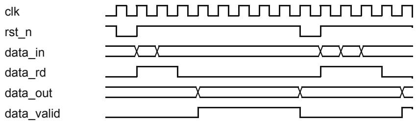
![clk\nrst_n\ndata_in\ndata_rd\ndata_out\ndata_valid](.spectra-ico-userguide/1984cd959546e105ddef6062de413b38e7ff7d271659b169b54f1c2de93ec031.jpg)

Figure 7 Perfect Hash Timing

The generated hasher is intended to be used within servants or clients and takes a 32-bit word input via the data\_in signal when the data\_rd signal is high. Two clock cycles after the last word is written to the hasher the data\_valid signal goes high if the string matches and the data\_out signal will be the matching value.

To run the PHG, use the phg script or phg.bat batch file. Running without parameters (or with a first parameter of -help) will display brief usage information as follows:

```txt
% phg -help
Usage: phg &lt;entity_name&gt; &lt;output_width&gt; { &lt;name&gt; &lt;value&gt; }
entity_name : the name of the generated VHDL entity
output_width : the width (in bits) of the mapped values
name / value : the name and value (in decimal) for a mapping
```

The SCA simulation example demonstrates the use of the PHG utility. The server\_resource server implements the PortSupplier interface, and a hasher is used to map between strings containing the port names and numeric identifiers. The hasher entity is generated using the following command:

```txt
% phg sca_hash 4 alpha 0 beta 1 gamma 2 theta 3 frequency 4 power 5
```

This produces a hasher entity called sca\_hash, with an output bit width of 4, mapping between the six specified pairs of names and values. The hasher is instantiated by the test bench and connected to server\_resource via the GPIO records.

# 5.9 ICO Development Lifecycle

The ICO development lifecycle is typically divided into a number of phases, as shown in Figure 8 and described more fully in the following sections.
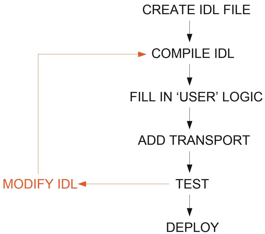
![The flowchart depicts a linear process with a feedback loop. The labeled blocks in the main vertical sequence are:\n\n*   **CREATE IDL FILE**\n*   **COMPILE IDL**\n*   **FILL IN 'USER' LOGIC**\n*   **ADD TRANSPORT**\n*   **TEST**\n*   **DEPLOY**\n\nThe connections are as follows:\n*   An arrow points downward from **CREATE IDL FILE** to **COMPILE IDL**.\n*   An arrow points downward from **COMPILE IDL** to **FILL IN 'USER' LOGIC**.\n*   An arrow points downward from **FILL IN 'USER' LOGIC** to **ADD TRANSPORT**.\n*   An arrow points downward from **ADD TRANSPORT** to **TEST**.\n*   An arrow points downward from **TEST** to **DEPLOY**.\n\nA feedback loop is indicated by orange arrows and text on the left side:\n*   An orange arrow points left from **TEST** to the text **MODIFY IDL**.\n*   An orange arrow points upward from **MODIFY IDL** and connects back to **COMPILE IDL**.](.spectra-ico-userguide/6ad74eda147bb7fb70410257c359ca994e9ce05e1c6321e7fa6a5a6cc20c56e7.jpg)

Figure 8 ICO Development Lifecycle

# 5.9.1 Create the IDL

The first step is to define the IDL entities that you wish to use within the system. The compiler will generate VHDL code according to the mapping specification— client and server entities and a top-level entity, which the developer then edits as required. For more information please refer to Chapter 3 of the OMG CORBA specification, ‘IDL Syntax and Semantics’.

An example of an IDL definition for a servant which receives a 32-bit number and increments it by one.

```txt
module TestModule
{
    interface TestServer
    {
    long incrementByOne (in long value);
    };
};
```

# 5.9.2 Compile the IDL

The compilation of the IDL is achieved by the IDL to VHDL compiler provided with ICO.

# 5.9.3 Integrate User Logic

In the example IDL above the incrementByOne operation sends a single long value to the servant and returns an incremented long value. The operation name differentiates between operations and allows the servant to direct the input parameters to their correct destination.

The sequence and timing of how and when data is sent and received by the bus is critical to the correct operation of ICO. The IDL to VHDL compiler provides the user with a VHDL file providing pre-built state machines that handle reads and writes to and from the bus. The following figures (Figure 9 on page 52 and Figure 10 on page 53) show the conceptual Finite State Machine (FSM) for both the client and servant for the example IDL.
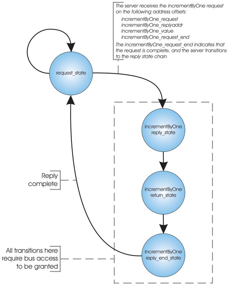
![The flowchart depicts a state transition system involving a main state and a sub-chain of states.\n\n**Labeled Blocks:**\n*   A blue circle labeled **request_state**.\n*   Inside a dashed rectangular boundary, three vertical blue circles labeled:\n    *   **incrementByOne reply_state**\n    *   **incrementByOne return_state**\n    *   **incrementByOne reply_end_state**\n\n**Connections and Annotations:**\n*   **request_state** has a self-looping arrow.\n*   A text box connected to **request_state** reads: 'The server receives the incrementByOne request on the following address offsets: incrementByOne_request incrementByOne_replyaddr incrementByOne_value incrementByOne_request_end The incrementByOne_request_end indicates that the request is complete, and the server transitions to the reply state chain'.\n*   An arrow connects **request_state** to **incrementByOne reply_state**.\n*   Arrows connect the blocks inside the dashed box in descending order: **incrementByOne reply_state** to **incrementByOne return_state**, and then to **incrementByOne reply_end_state**.\n*   A label next to the dashed box reads: 'All transitions here require bus access to be granted'.\n*   An arrow connects **incrementByOne reply_end_state** back to **request_state**.\n*   This return arrow is labeled: 'Reply complete'.](.spectra-ico-userguide/97b0500c45188d6778cf9a5be0b34f935cbb610958052ca47389c62d0ee696aa.jpg)

Figure 9 Servant Finite State Machine
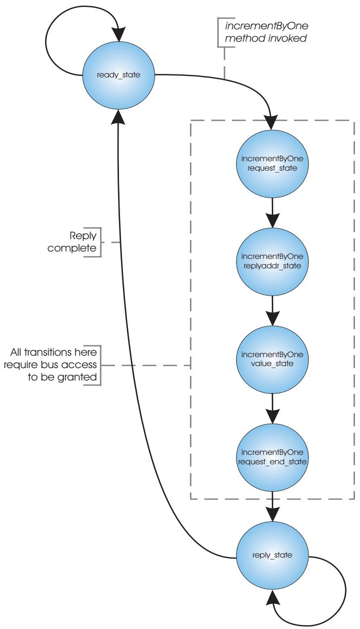
![This flowchart depicts a state machine with the following labeled blocks and connections:\n\n**Blocks:**\n*   `ready_state`\n*   `incrementByOne request_state`\n*   `incrementByOne replyaddr_state`\n*   `incrementByOne value_state`\n*   `incrementByOne request_end_state`\n*   `reply_state`\n\n**Connections and Flow:**\n*   **`ready_state`**: Has a self-loop. An arrow labeled `incrementByOne method invoked` leads from here to `incrementByOne request_state`.\n*   **Dashed Box Sequence**: A vertical sequence of states is enclosed in a dashed box annotated with 'All transitions here require bus access to be granted'. The flow proceeds downwards:\n    *   `incrementByOne request_state` → `incrementByOne replyaddr_state`\n    *   `incrementByOne replyaddr_state` → `incrementByOne value_state`\n    *   `incrementByOne value_state` → `incrementByOne request_end_state`\n*   **`reply_state`**: An arrow connects from `incrementByOne request_end_state` to this block. It has a self-loop.\n*   **Return Path**: An arrow labeled `Reply complete` leads from `reply_state` back to `ready_state`.](.spectra-ico-userguide/41eaa855afbf1cdb23f9e62bedc0bec68f6f9c9f8949cfeb642a3b309559d7b1.jpg)

Figure 10 Client Finite State Machine

For the servant case the FSM idle state is request\_state. It will remain in this state until the servant has received all of the request data sent to it by a client and it has been granted access to the bus. The FSM will then proceed to go through all of the reply states required to send data on the bus. Once the reply is complete, the servant’s FSM returns to request\_state.

It is the user’s responsibility to provide the data to the servant when the state relevant to that piece of data is reached. This can be done by editing procedures that are generated by the IDL compiler. The state machine code uses these procedures to obtain the required data. The file containing the procedures is the only file that user needs to modify.

A special procedure named idle\_action is generated for clients. This procedure is used to initiate the sequences of states that produce a request. The enumeration action is set to the appropriate value to start a request.

Writes to the servant arbitration granting access to the bus are illustrated by the timing diagram in Figure 11 on page 54.

The busy line is asserted high to indicate that this servant is now busy and subsequently unable to handle any more requests. The receiving bridge addresses the servant via the adr\_i (address bus in), dat\_i (data bus in) and write\_i.
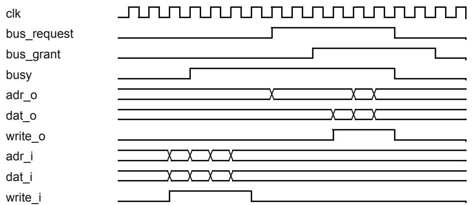
![clk\nbus_request\nbus_grant\nbusy\nadr_o\ndat_o\nwrite_o\nadr_i\ndat_i\nwrite_i](.spectra-ico-userguide/0193172421f56bcfccdfd35ca583e64b686fa51a74e92e08ed92918f1967f329.jpg)

Figure 11 Bus To Servant Write

One data word is transferred per clock cycle. The data may be written in contiguous cycles or the write\_i signal may go low for one or more clock cycles (see Figure 12).
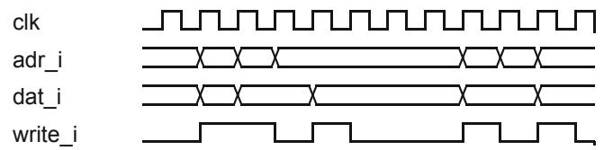
![clk\nadr_i\ndat_i\nwrite_i](.spectra-ico-userguide/8a06db0393a55ee27606793ed07ebcf862f143eaef2885cee8c874792eabed67.jpg)

Figure 12 Bus Write Timing

The generated code also controls the bus\_request signal to request access to the bus and the state machine progresses through the reply states only when the bus\_grant signal is high. Note that this bus arbitration occurs on both the input bus and output buses.

Once all the data has been sent the bus must be released to allow other bridges, servants or clients to access the bus. This occurs when the busy line drops low together with the bus\_request and bus\_grant lines. The bus arbitration scheme will then release the bus and allow another message to enter the servant. It is important to note that in the case of multiple clients and servants there are logically two buses, one for incoming data and one for outgoing data. This means that once a servant has finished receiving data it will not block other servants or clients.
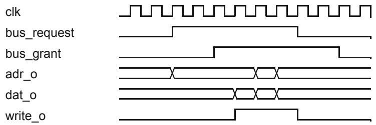
![clk\nbus_request\nbus_grant\nadr_o\ndat_o\nwrite_o](.spectra-ico-userguide/18ba42ffc58797e81ea559cd4b38da68b38ca2af95a6fea56ea01e323b43157e.jpg)

Figure 13 Servant To Bus Write

# 5.9.4 Obtaining the ICO servant IOR

CORBA uses Interoperable Object References (IORs) to identify individual servants. The IOR will contain one or more profiles with each profile providing endpoint information for a particular form of transport as well as object key data.

Since ICO is designed to be used with a user specified transport the IDL compiler can only supply the object key part of an IOR. The IDL compiler generates an initial\_references.txt file that contains partial IORs in the form of ‘corbalocs’. A corbaloc is an IOR in a readable string form and consists of a corbaloc prefix, endpoint information and the object key encoded as a string1 . The generated text file will contain lines in the form:

```txt
-ORBInitRef server_demo=corbaloc:&lt;PROTOCOL&gt;:&lt;ENDPOINT&gt;/%01
```

The user must substitute the appropriate values for protocol, host and endpoint. These values will depend on the type and configuration of the transport connected to ICO. An ORB which supports the addition of transports (such as e\*ORB) will then be capable of using the above form of initial object references to connect to the ICO server.

Using non-standard (for CORBA) transports will require the appropriate transport extension to be implemented for the software ORB.

In circumstances where the corbaloc form cannot be used, such as passing the reference via a CORBA program that does understand the transport in use, then a ‘stringified’ IOR will be required. A stringified IOR contains a textual encoding of the binary form of the object reference. The corbaloc IOR can be converted to the stringified form using a small CORBA program that takes the corbaloc as input and prints the stringified IOR.

```c
#include "eOrbC/orb.h"
int main (int argc, char **argv)
{
    CORBA_Environment ev;
```

1. Object key data is encoded using RFC 2396 escape convention.

```c
CORBA_Object obj;
CORBA_ORB orb;
char *str;

/* Install plugins */

EORB_IIOP_plugin();

if (argc != 2)
{
    fprintf (stderr, "usage: convert corbaloc:\...\n");
    return -1;
}

/* Initialize the ORB */

orb = CORBA_ORB_init (&argc, argv, "eorb-ce", &ev);
EORB_CHECK_EXC_RETURN_VAL ("CORBA_ORB_init", &ev, -1);

/* Resolve the server */

obj = CORBA_ORB_string_to_object (orb, argv[1], &ev);
EORB_CHECK_EXC_RETURN_VAL ("string_to_object", &ev, -1);

str = CORBA_ORB_object_to_string (orb, obj, &ev);
EORB_CHECK_EXC_RETURN_VAL ("object_to_string", &ev, -1);

printf ("ior = %s\n", str);

/* Clean up */

CORBA_string_free (str);
CORBA_Object_release (obj, &ev);
CORBA_ORB_destroy (orb, &ev);

return 0;
```

# 5.10 ICO Development Examples

The ICO distribution is supplied with a number of examples, which can be found in the examples directory. Two of these examples are described here.

# 5.10.1 Increment by One Example

This section uses the ‘increment by one’ simulation example to illustrate the steps needed to design, implement and simulate an ICO server. This example is installed in the examples/simulation/incbyone directory.

# 5.10.1.1 Design

The first step is to define the server’s operations in IDL. In this example we only need one operation that will take in a numeric value and return the incremented value. This example is in a file called incbyone.idl:

```txt
module TestModule
{
    interface TestServer
    {
    long incrementByOne (in long n);
    };
};
```

The server will be implemented in VHDL. It will store the result of adding one to the number passed during the request, and return the incremented value in the reply. The client will be implemented in C using e\*ORB and will issue requests from a GPP (e.g. the host PC).

# 5.10.1.2 Implementing The Server

Run the IDL compiler with the command line below. The compiler will use the example library for the generated code, which will be placed in the current directory. The only servant needed is a single instance of the server, and the compiler will generate a default receive/transmit bridge pair.

```batch
% idlv -library example -server incserver 1
TestModule::TestServer incbyone.idl
```

Alternatively, issue the following command to run the ICO IDL compiler as above and also generate the client executable:

```txt
% scons -u
```

To implement the servant, edit the generated incserver\_pkg.vhd file and add the required implementation logic. Since the result value needs to be stored, an appropriate entry needs to be added to the incby\_one\_register\_type record. Add the field:

```sql
result : CORBA_long;
```

Next change the constant incby\_one\_register\_init used as the reset state to reflect the change to the record definition by adding:

```txt
result => (others => '0')
```

The field result needs to be set when the value parameter is supplied. When the value is written to the servant the TestServer\_incrementByOne\_n procedure is invoked. The signal value will contain the n value. Record the incremented value in t h e u s e r s t a t e b y a d d i n g t h e f o l l o w i n g l i n e a s t h e b o d y o f t h e TestServer\_incrementByOne\_n procedure:

```javascript
v.result := value + 1;
```

Next, the incremented value needs to be returned in the server’s reply. The state m a c h i n e t h a t g e n e r a t e s t h e r e p l y w i l l i n v o k e t h e p r o c e d u r e TestServer\_incrementByOne\_return at the appropriate time. Complete the i m p l e m e n t a t i o n b y a d d i n g t h e f o l l o w i n g l i n e t h e b o d y o f t h e TestServer\_incrementByOne\_return procedure:

```javascript
result := r.result;
```

The completed package is shown below. Since this example contains no sequences or arrays, each operation (excluding default\_action) will be invoked exactly once and the operations will be invoked in the order that they appear in the source code.

```vhdl
package incserver_pkg is
    type incserver_in_type is record
    dummy: std_logic;
    end record;

    type incserver_out_type is record
    dummy: std_logic;
    end record;

    constant incserver_out_init: incserver_out_type :=
    (
    dummy => '0'
    );

    type incserver_register_type is record
    output: incserver_out_type;
    result: corba_ulong;
    end record;

    constant incserver_register_init: incserver_register_type :=
    (
    output => incserver_out_init,
    result => (others => '0')
    );

    -- procedure declarations removed for clarity

end package incserver_pkg;

package body incserver_pkg is

procedure default_action
(
    r: incserver_register_type;
    d: incserver_in_type;
    variable v: inout incserver_register_type
) is
begin
end procedure default_action;

-- ::TestModule::TestServer::incrementByOne
procedure TestModule_TestServer_incrementByOne_request(
    r: incserver_register_type;
    d: incserver_in_type;
    variable v: inout incserver_register_type
) is
begin
end procedure TestModule_TestServer_incrementByOne_request;

procedure TestModule_TestServer_incrementByOne_value
(
    r: incserver_register_type;
    d: incserver_in_type;
    variable v: inout incserver_register_type;
    value: corba_long
) is
begin
v.result := value + 1;
end procedure TestModule_TestServer_incrementByOne_value;

procedure TestModule_TestServer_incrementByOne_request_end
(
    r: incserver_register_type;
    d: incserver_in_type;
    variable v: inout incserver_register_type
```

```vhdl
) is
begin
end procedure TestModule_TestServer_incrementByOne_request_end;
procedure TestModule_TestServer_incrementByOne_return
(
    r: incserver_register_type;
    d: incserver_in_type;
    variable v: inout incserver_register_type;
    variable ready: inout boolean;
    variable value: out corba_long
) is
begin
    value := r.result;
end procedure TestModule_TestServer_incrementByOne_return;
end incserver_pkg;
```

# 5.10.1.3 Implementing the Client

The client is implemented in C and built using e\*ORB. It initialises the ORB instance, obtains a reference to the server via an initial reference set up on the command line, performs the call to the server, reports the results, and cleans up.

Please refer to the e\*ORB C User Guide for use of e\*ORB on your host platform.

An SCons build file is provided; to build the client executable, enter ‘scons -u’ in the incbyone directory.

# 5.10.1.4 Simulation

To run this example under simulation, start ModelSim with the following command:

```batch
% vsim -do "build.do"
```

The script will compile all the required code, start a simulation with the top\_devboard\_tb entity, set up the waveform window, run by 10ns to move past the test bench reset and start the tb\_server process defined in the server.tcl file.

With the server running, start the client and perform the call to the server. The client r e s o l v e s t o t h e s e r v e r u s i n g t h e i n i t i a l r e f e r e n c e ‘ i c o ’ . T h e object\_keys\_pkg.vhd file shows that the compiler has allocated object key 1 to the server. Launch the client with the following command from the incbyone directory, replacing ‘modelsim\_host’ with the appropriate host name:

# Linux

On Linux systems:

```txt
% client -ORBInitRef ico=corbaloc:iiop:modelsim_host:9001/%01
```

# WIN

On Windows systems:

```txt
% client.exe -ORBInitRef ico=corbaloc:iiop:modelsim_host:9001/%01
```

The client will initialise the ORB, resolve to the server and perform the call.

# 5.10.2 LEDs Example

The following example shows how to implement a simple output interface driving a set of LEDs on a Altera Cyclone III development board. The completed example can be found in the examples/synthesis/cyclone\_III\_leds directory. The IDL used is shown below:

```txt
module Demo
{
    interface DevBoard
    {
    oneway void leds (in octet value);
    };
};
```

Compile the IDL with ICO compiler:

```batch
% idlv -server leds 1 Demo::DevBoard Demo.idl
```

The next step is to define the output signals. Edit the leds\_pkg.vhd file and replace the dummy field in leds\_out\_type with:

```txt
leds: std_logic_vector(7 downto 0);
```

The leds\_in\_type and leds\_register\_type records are not used in this example and are not modified. The constant leds\_out\_init must be adjusted to reflect the change to leds\_in\_type by replacing the dummy initialisation with:

```txt
leds => (others => '0');
```

Next the output is set to the inverse of the supplied octet value (as the FPGA signals are connected to the LED cathodes). A line assigning to the output variable has been added to the DevBoard\_value\_in procedure:

```vhdl
procedure DevBoard_leds_value_in
(
    r: leds_register_type;
    d: leds_in_type;
    variable v: inout leds_register_type;
    value : corba_octet
) is
begin
v.output.leds := not std_logic_vector(value);
end procedure DevBoard_leds_value_in;
```

This procedure will be invoked at the point that the value parameter is recieved by the servant. The top\_devboard.vhd file connects the ouput signals from the servant to the LEDs using the signal provided by the generated ico\_tle component.

```txt
signal leds_out : leds_out_type;
tle : ico_tle
    port map
    (
    reset_n => reset,
```

```txt
clk => clk,
transport_in => trans_in,
transport_out => trans_out,
leds_in => (others => '0'),
leds_out => leds_out
);
user_led &lt;= leds_out.leds;
```

# 5.11 Generating Sequences

When a servant or client produces a sequence as an output (out parameter or return for a servant, in parameter for client) then the user code must specify the length of the sequence. ICO generates skeleton code with defined constants for each output sequence. If a fixed-size sequence is required then the user can set the value of the corresponding constant to the correct value (the default sequence length is zero, giving an empty sequence).

If a variable sequence length is required (for example the required length is set by a previous operation) then the length can be recorded in a register and the register used in place of the sequence length constant. The constants are passed as the second argument to a start\_sequence procedure call and are required to be of type corba\_ulong.

The example found in examples/simulation/twoway\_sequence illustrates generating variable length sequences. The example interface includes a setup operation that sets the length of sequence required and a receive operation that returns a sequence.

```c
module SequenceDemo
{
    interface Transfer
    {
    typedef sequence &lt;octet&gt; OctetSeq;
    void setup (in unsigned long size);
    octet send (in OctetSeq data);
    void receive (out OctetSeq data);
    octet swap (inout OctetSeq data);
    };

    interface Config
    {
    unsigned long getRegisterValue (in octet_regAddress);
    void setRegisterValue (in octet_regAddress, in unsigned long regValue);
    };
};
```

A f i e l d l e n g t h o f t y p e c o r b a \_ u l o n g h a s b e e n a d d e d t o t h e transfer\_register\_type record in the transfer\_pkg (found in transfer\_pkg.vhd).

```rust
type transfer_register_type is record
    output: transfer_out_type;
    length: corba_ulong;
    result: corba_octet;
end record;
```

The implementation of the setup operation sets the length field to incoming size parameter:

```vhdl
procedure SequenceDemo_Transfer_setup_size (
    r: transfer_register_type;
    d: transfer_in_type;
    variable v: inout transfer_register_type;
    value: corba_ulong
) is
begin
    v.length := value;
end procedure SequenceDemo_Transfer_setup_size;
```

The SequenceDemo\_Transfer\_receive\_data\_out\_length procedure is used to supply the length the reply sequence.

```vhdl
procedure SequenceDemo_Transfer_receive_data_out_length (
    r: transfer_register_type;
    d: transfer_in_type;
    variable v: inout transfer_register_type;
    variable ready: inout boolean;
    variable value: out corba_ulong
) is
begin
    value := r.length;
end procedure SequenceDemo_Transfer_receive_data_out_length;
```

The procedure SequenceDemo\_Transfer\_receive\_data\_out will then be invoked zero or more times depending upon the value in r.length. Note that in this example an octet sequence is being generated, therefore four octets are written for each invocation.

# 5.12 Using the CORBA Any Type

ICO can receive and send parameters of type Any. The value contained in the Any must be a primitive value or string (see Section 4.2.8, Any Mapping, on page 32). When an Any parameter is used a range of addresses are allocated to the parameter with separate addresses for each type that could contained in the Any. When receiving an Any parameter the address (or addresses) corresponding to the type contained in the Any will be used and the data contained in the Any placed on the data bus. The generated VHDL code will contain case statements for each of the possible types for an Any parameter. When sending an Any parameter the same process is followed with the data to be contained in the Any written to the data bus using an address corresponding to the type of the data.

The example found in examples/simulation/sca illustrates sending and receiving Any parameters. The file resource\_pkg.vhd implements a configure operation that receives as a parameter a sequence of DataType structures and a query operation that both receives and sends sequences of DataType. The DataType structure has a field value of type Any. The following IDL excerpt shows the definition of the operations and types:

```txt
module CF {
    struct DataType {
```

```cpp
string id;
any value;
};
typedef sequence &lt;DataType&gt; Properties;
interface PropertySet {
    void configure (in CF::Properties configProperties)
    raises (PropertySet::InvalidConfiguration,
    PropertySet::PartialConfipropertySet::PartialConfiguration);
    void query (inout CF::Properties configProperties)
    raises (UnknownProperties);
}
```

The implementation of the configure operation is only interested in two of the potentially contained types. In each case it records the value in a register for later use. For example the code that handles a unsigned long value field is:

```vhdl
procedure CF_PropertySet_configure_configProperties_value_ulong
(
    r: resource_register_type;
    d: resource_in_type;
    variable v: inout resource_register_type;
    value: corba_ulong
) is
begin
    v.ulong_value := value;
end procedure
CF_PropertySet_configure_configProperties_value_ulong;
```

The implementation of the query operation sends Anys containing unsigned short and unsigned long values:

```vhdl
procedure CF_PropertySet_query_configProperties_out_value_ushort
(
    r: resource_register_type;
    d: resource_in_type;
    variable v: inout resource_register_type;
    variable ready: inout boolean;
    variable value: out corba_ushort
) is
begin
    value := corba_ushort(r.output.power);
end procedure
CF_PropertySet_query_configProperties_out_value_ushort;

procedure CF_PropertySet_query_configProperties_out_value_ulong
(
    r: resource_register_type;
    d: resource_in_type;
    variable v: inout resource_register_type;
    variable ready: inout boolean;
    variable value: out corba_ulong
) is
begin
    value := corba_ulong(r.output.frequency);
    v.require_freq := '0';
end procedure
CF_PropertySet_query_configProperties_out_value_ulong;
```

S e l e c t i o n o f t h e a p p r o p r i a t e s t a t e i s p e r f o r m e d b y t h e CF\_PropertySet\_query\_configProperties\_out\_value procedure.

```txt
procedure CF_PropertySet_query_configProperties_out_value (
    r: resource_register_type;
    d: resource_in_type;
    variable v: inout resource_register_type;
    variable ready: inout boolean;
    variable any_type: out corba_any_type
) is
begin
    if r.require_freq = '1' then
    any_type := any_ulong;
    else
    any_type := any_ushort;
    end if;
end procedure CF_PropertySet_query_configProperties_out_value;
```

# TRANSPORTS

# CHAPTER

# Transports

# 6.1 Introduction

When we talk about a transport within the context of ICO, we are referring to the protocol component such as TCP, UDP, Ethernet, RapidIO or PCIe, as opposed to the electrical standard.

An ICO transport refers to the interface that ICO uses to receive and transmit data together with the layout of the data as defined by the transport protocol. In order for ICO to effectively interact with a desired transport, the transport is required to deliver the data payload carried by it in either a streaming or packeted format.

After a message has been received, properly aligned and decoded by the transport it is passed on to an ICO receive (Rx) bridge using a simple FIFO interface as shown in Figure 14 on page 68. In this diagram there are three transports indicated by the colours yellow, green and red. The different colours signify either a number of electrical connections to different transports or a number of different physical connections to a single transport.

Each transport connection (red, yellow or green) has a set of connection identifiers which are passed to ICO at the start of any GIOP message that differentiates protocol connections.

For example, if we process a received PCIe TLP packet we need to extract from the header the address and ID of the sender and store it in order to be able to reply to a CORBA request.

This address and ID are associated with a unique key which relates to this transport and in the case of connection orientated transports the connection as well. This key is then passed up to ICO as a Connection Id (CID) and used on the transmit of a GIOP message to indicate which transport and what connection the message should go to.

The ideas above are expanded upon in the following sections.

# 6.2 Transport Connections
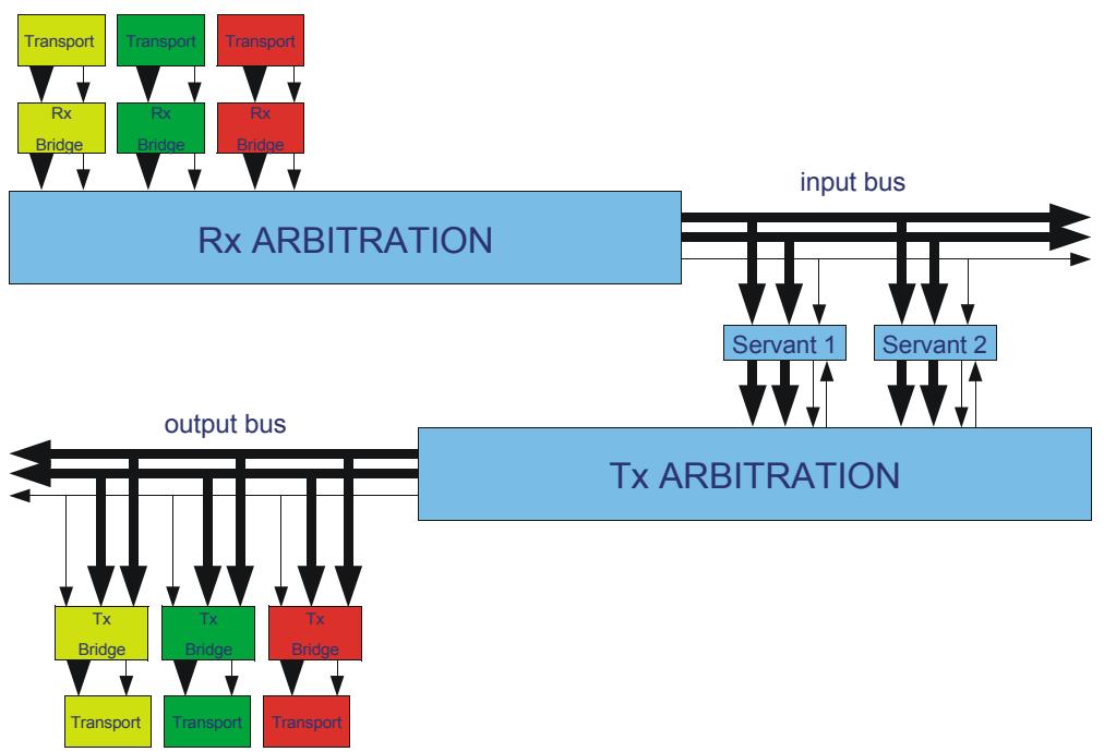
![Based on the provided image, here is an accurate and concise description of the flowchart:\n\n**Labeled Blocks:**\n*   **Top Row:** Three 'Transport' blocks (colored yellow, green, and red).\n*   **Second Row:** Three 'Rx Bridge' blocks (colored yellow, green, and red).\n*   **Middle Left:** A large 'Rx ARBITRATION' block.\n*   **Middle Right:** Two 'Servant' blocks labeled 'Servant 1' and 'Servant 2'.\n*   **Bottom Right:** A large 'Tx ARBITRATION' block.\n*   **Bottom Left:** Three 'Tx Bridge' blocks (colored yellow, green, and red).\n*   **Bottom Row:** Three 'Transport' blocks (colored yellow, green, and red).\n*   **Buses:** 'input bus' and 'output bus'.\n\n**Connections:**\n*   **Input Path:** Each top 'Transport' block has downward arrows pointing to its corresponding 'Rx Bridge' block. These 'Rx Bridge' blocks have downward arrows connecting to the 'Rx ARBITRATION' block.\n*   **Arbitration & Servants:** The 'Rx ARBITRATION' block outputs to the right onto the 'input bus'. This bus connects bidirectionally (arrows pointing up and down) to both 'Servant 1' and 'Servant 2'. Additionally, downward arrows connect 'Servant 1' and 'Servant 2' to the 'Tx ARBITRATION' block.\n*   **Tx Arbitration & Buses:** The 'Tx ARBITRATION' block has bidirectional arrows (up and down) connecting it to the 'input bus'. It also has leftward arrows connecting it to the 'output bus'.\n*   **Output Path:** The 'output bus' connects via downward arrows to the three 'Tx Bridge' blocks. These bridges then have downward arrows connecting to their corresponding bottom 'Transport' blocks.](.spectra-ico-userguide/3d75ab50a0218b2055a5cb5722b904e132e7b048e4bbb944d0e24ab90c40a60c.jpg)

Figure 14 Connections in ICO

Figure 14 above shows how a connection is made to ICO. A receive bridge may have a corresponding transmit bridge and serve as a bridge between the transport and the CORBA world. The receive bridge translates messages from the outside world from the GIOP v1.0 format to the BIOP protocol.

The bridges are designed to consume data as quickly as possible together with providing as little push-back as possible, given the arbitration scheme chosen and the number of transports involved.

Each receive bridge is connected to the same arbitration block which controls access to the input bus that feeds servants and clients. In turn every servant and client is connected to an outgoing transmit arbitration block which controls access to the output bus. The separation between input and output buses allows full duplex communication to occur such as a servant receiving a message while another servant or client is sending one. This in turn increases the bandwidth of ICO and minimises bus contention.

ICO has one interface for receiving messages and one interface for transmitting messages per receive/transmit bridge pair. The messages transferred on both transmit and receive interfaces are in GIOP format and should be treated by lower level blocks as raw non-encapsulated data.

The part of the TLE entity definition relevant to the bridges is shown below. By design, the bridges closely resemble a set of FIFO interfaces with 32-bit data ports. The TLE is using the default pair of bridges and connection support and object keys are both enabled. The databus and ConnectionID subtypes are defined in the ico bus package, and are 32 bits and 8 bits wide respectively. The key\_index\_type subtype is defined in the output\_engine\_pkg package and is 8 bits wide.

```vhdl
entity ico_tle is
    generic
    (
    transport_config : transport_config_type := (2, 5, 12)
    );
    port
    (
    reset_n : in std_logic;
    clk : in std_logic;
    -- Signals for transport.
    transport_out : in transport_out_type;
    transport_in : out transport_in_type;
    ...
    );
end ico_tle;
```

Each transport is represented by a pair of signal records. The records are:

```vhdl
type transport_in_type is record
    data : slv32;
    valid : std_logic;
    full : std_logic;
    id : ConnectionID;
end record;
type transport_out_type is record
    data : slv32;
    wr : std_logic;
    rd : std_logic;
    id : ConnectionID;
end record;
```

Table 8 Transport Interface Description

<table><tr><td>Signal Name</td><td>I/O</td><td>Description</td><td>Optional</td></tr><tr><td>reset_n</td><td>I</td><td>Reset signal. This signal is active low and asynchronous.</td><td>No</td></tr><tr><td>clk</td><td>I</td><td>Clock signal.</td><td>No</td></tr><tr><td>transport_out.id</td><td>I</td><td>Connection Id. 8 bits.</td><td>No</td></tr><tr><td>transport_out.data</td><td>I</td><td>Transport data in. 32 bits.</td><td>No</td></tr><tr><td>transport_out.wr</td><td>I</td><td>Transport data input write. Indicates ipb_fifo_in_data is valid.</td><td>No</td></tr><tr><td>transport_in.full</td><td>O</td><td>Input FIFO full indicator. Asserted when the remaining space in the FIFO is at or below the value specified by the ipb_fifo_in_low generic parameter.</td><td>No</td></tr><tr><td>transport_in.id</td><td>O</td><td>Connection Identifier. 8 bits.Set to zero if not needed.</td><td>No</td></tr><tr><td>key_index</td><td>O</td><td>Index of object key word. 8 bits.</td><td>Yes</td></tr><tr><td>key_data</td><td>I</td><td>Object key data. 32 bits.</td><td>Yes</td></tr><tr><td>transport_in.wr</td><td>O</td><td>Asserted when transport output data is valid.</td><td>No</td></tr><tr><td>transport_in.data</td><td>O</td><td>Transport output data. 32 bits.</td><td>No</td></tr><tr><td>transport_out.rd</td><td>I</td><td>Transport output data read signal.Asserted when the transport is ready to accept data. When de-asserted there will be up to a 4 cycle delay before data transmission is ceased.</td><td>No</td></tr></table>

Table 9 Transport Generics Description

<table><tr><td>Name</td><td>Description</td></tr><tr><td>transport_config.fifo_in_low</td><td>The low value for remaining space in the input FIFO at which to assert the ipb_fifo_in_full signal.</td></tr><tr><td>transport_config.fifo_in_size</td><td>Size of input FIFO in words as power of two value. For example, a value of 4 implies 16 x 32-bit words.</td></tr><tr><td>transport_config.out_buffer_size</td><td>Size of output buffer in bytes as power-of-two value. For example a value of 11 implies a 2048 byte buffer. Note that this value must be chosen such that the buffer is large enough for any required GIOP reply message.</td></tr></table>

For the case of non-default bridges, each receive bridge has the same signals as for ipb and each transmit bridge the same signals for opb above. The bridge names are composed o $\mathrm { ~ f ~ } ^ { \circ } \dot { \bar { \mathrm { ~ \scriptsize ~ 1 ~ p b ~ } } } ,$ or ‘opb’ followed by the base name given to the compiler followed by a numeric suffix if the bridge count was greater than one, separated with underscores.

For example, the command line below specifies one bridge pair with a base name of ‘ n o c h e c k s ’ t h a t d o e s n o t p e r f o r m c h e c k s f o r t h e I N V \_ O B J R E F, OBJECT\_NOT\_EXIST and BAD\_OPERATION exceptions. The byte ordering will be ‘auto’ for the receive bridge (the receive bridge will use the GIOP message header information to determine which byte ordering is in use) and big-endian for the transmit bridge. One instance of this bridge pair will be instantiated in the TLE. The command specifies a second bridge pair with a base name of ‘standard’ that does check for the exceptions and uses little-endian byte ordering for both the receive and transmit bridges; the TLE will instantiate 2 instances of this bridge pair. The enable\_objectkey option applies to all bridges.

```batch
% idlv -bridge nochecks 1 auto big false false false -bridge standard 2 little little true true true true -enable_objectkey test.idl
```

This leads to the following bridge-related ports in the TLE entity definition:
```vhdl
component ico_tle
generic
(
    transport0_config : transport_config_type := (2, 5, 12);
    transport1_config : transport_config_type := (2, 5, 12);
    transport2_config : transport_config_type := (2, 5, 12)
);

port
(
    reset_n : in std_logic;
    clk    : in std_logic;

    -- Signals for transport0.
    transport0_out : in transport_out_type;
    transport0_in : out transport_in_type;

    -- Signals for transport1.
    transport1_out : in transport_out_type;
    transport1_in : out transport_in_type;

    -- Signals for transport2.
    transport2_out : in transport_out_type;
    transport2_in : out transport_in_type;

    -- Object key signals for transport0.
    key0_index   : out key_index_type;
    key0_data   : in slv32;

    -- Object key signals for transport1.
    key1_index   : out key_index_type;
    key1_data   : in slv32;

    -- Object key signals for transport2.
    key2_index   : out key_index_type;
    key2_data   : in slv32;

    -- User I/O signals for bus object default.
    default_in   : in default_in_type;
    default_out   : out default_out_type
);

end component;
end package;
```

# 6.2.1 Receive (Rx) Interface

Figure 14 on page 68 shows how a connection to a transport such as Ethernet is realised within ICO. For protocols supporting two-way messaging, a receive bridge has a corresponding transmit bridge which serves as a translation service between the transport and the CORBA world. The bridge translates messages from the outside world in GIOP v1.0 format into the BIOP bus protocol used by ICO. BIOP was designed with the ability to be layered on top of a variety of common bus standards and as such is pluggable.

The bridges have been optimised to minimise latency by consuming data in a fully pipelined manner, reducing push-back on transport blocks and enabling faster data transfer.

Each receive bridge is connected to an arbitration block that controls access to the bus, passing data to and from servants and clients. In turn every servant and client is connected to an outgoing arbitration block which controls access to the outgoing bridges. These arbitration blocks implement a simple round robin arbitration scheme. This allows for different schemes to be implemented without affecting the top level entity of ICO in a very simple manner.

The receive interface comprises the transport\_out.data bus and transport\_out.wr write strobe. Data flows into ICO on transport\_out.data and must be valid on the rising edge of the clock when transport\_out.wr is asserted.

clk transport\_out.data transport\_out.wr

![Pure electrical circuit lines without any symbols](.spectra-ico-userguide/ecda1130de237d47b0ee6ff729599853209f1c5e15d1fcaf2a5bef7004118203.jpg)

Figure 15 ICO Incoming Data

T h e t i m i n g o f t h e d a t a c o m i n g i n t o I C O f r o m t h e t r a n s p o r t o n transport\_out.data and transport\_out.wr is shown in Figure 15. The input to ICO is a simple FIFO interface where the data must be present at the time the write signal goes high. The write signal transport\_out.wr may go low at any time as long as it is synchronous with the clock, as shown in the diagram and must go low one clock cycle after transport\_in.full goes high.

The bus transport\_out.data is 32 bits wide with the first octet of data in bits 31 to 24, the second octet in bits 23 to 16, the third octet in bits 15 to 8 and the fourth octet in bits 7 to 0. If the total GIOP message length is not a multiple of four bytes, additional bytes must be added to the last word of the message to pad the message so that the length is a multiple of four bytes. The message alignment block can perform this task as described in Section 6.3, Packet Based Transports, on page 73.

# 6.2.2 Transmit (Tx) Interface

The transmit interface comprises the transport\_in.data bus and the transport\_in.wr write strobe. Data flows out of ICO on transport\_in.data and is valid on the rising edge of the clock when transport\_in.wr is asserted. Again as in the case of the receive direction, if the data width of the connection between ICO and the transport is not 32 bits wide, an additional FIFO with parametrisable input and output ports can be added to provide the desired data width transformation while maintaining the same timing characteristics.

For data coming out of ICO on transport\_in.wr and transport\_in.data the timing is shown in Figure 16. The output from ICO resembles a FIFO interface. ICO will write out the entire message contained in its internal buffers by asserting the transport\_in.wr signal and passing the message 4 bytes at a time through transport\_in.data. Valid data is indicated by the strobe transport\_in.wr going high.

clk

transport\_in.wr

transport\_in.data

transport\_out.rd

![Pure electrical circuit lines without any symbols](.spectra-ico-userguide/91c5824064d3733da3cf118985803b603f4082b5769fc0d7789e1ff12388d011.jpg)

Figure 16 ICO Outgoing Data

The data format on the Tx interface is different from that of the input. To allow the transport developer to ascertain where one CORBA message begins and another one ends, ICO places a 32-bit big-endian length at the start of every message. The transport developer can add control logic to identify when a write from ICO to the transport has occurred and store the length of the message in a register. This length is decremented at every subsequent write. When the length register has reached zero the present message has finished and the transport will be provided with a new message on the next write from ICO.

clk

transport\_in.wr

transport\_in.data

transport\_out.rd

![Pure electrical circuit lines without any symbols](.spectra-ico-userguide/3a5d46ef6ee2cd9833f69205420c281f0367b5810221a6f182aee79796899bf0.jpg)

Figure 17 Transmit Flow Control

The transport\_out.rd signal provides a simple flow control mechanism (see Figure 17). If the transport\_out.rd signal is low then the transmit data will be halted. If the transport\_out.rd signal transitions from high to low during the transmission of a message then the transport\_in.wr signal will go low one clock cycle later. If the transport\_out.rd signal transitions from low to high then the transport\_in.wr signal will go high on the next clock cycle (if there is more data to be transmitted).

# 6.3 Packet Based Transports

For some packet based transports the interface requires that the start, end and length of a message is passed at the start of transmission. An example entity declaration for example\_transport is given below.

```txt
entity example_transport is
port
{
    clk : in std_logic;
    rst : in std_logic;
--Rx
    data_in : in std_logic_vector(31 downto 0);
```

```vhdl
data_in_ready : out std_logic;
data_in_valid : in std_logic;
data_in_addr : in std_logic_vector(31 downto 0);
start_of_packet : in std_logic;
end_of_packet : in std_logic;
data_in_size : in std_logic_vector(31 downto 0);
--Tx
data_out : out std_logic_vector(31 downto 0);
data_in_ready : in std_logic;
data_in_valid : out std_logic;
data_out_addr : out std_logic_vector(31 downto 0);
start_out_packet : out std_logic;
end_out_packet : out std_logic;
data_out_size : out std_logic_vector(31 downto 0);
};
end entity;
```

# 6.3.1 Receiving Packets

The timing of a typical packet transfer for the interface is shown in Figure 18.When a packet is received by ICO, only the ports data\_in and data\_in\_wr are required and can be connected directly to the Rx ports of ICO as described above, if and only if the start of the GIOP message is guaranteed to be aligned to a four-byte boundary. In cases where the start and end of a GIOP message are not known a priori in the sent packet, a realignment block is required to be inserted between ICO and the transport. This block will search for the standard protocol message header ‘GIOP’, check the packet for correct formulation and then align data to a 4-byte boundary before passing it on to ICO. The block will also track the message length and indicate when a complete GIOP message has been received. Another GIOP message may follow immediately after it with possibly a different alignment.

![| Event           | Start (approx) | End (approx) |\n|-----------------|----------------|--------------|\n| reset_n         | 1              | 10           |\n| clk             | 2              | 10           |\n| data_in         | 3              | 10           |\n| data_in_ready   | 4              | 10           |\n| data_in_valid   | 5              | 10           |\n| start_of_packet | 6              | 10           |\n| end_of_packet   | 7              | 10           |\n| data_in_address | 8              | 10           |\n| data_in_size    | 9              | 10           |](.spectra-ico-userguide/c72a9ce397e99c6312f76d401190e18b688c818100f68643091eb0050e825f20.jpg)

Figure 18 Receiving Packets

# 6.3.2 Transmitting Packets

For transmission extra work is required to connect ICO to a packet-based network transport with timing as shown in Figure 19. A 32-bit length is passed at the start of an ICO packet which should be written to a data\_out\_size register. Using a Finite State Machine together with the data\_out\_size counter, the start and end of packet strobes can be synthesised.

The start of the packet strobe can be set to go high when the second write of a message is received from ICO (i.e. the next write after the length has been sent). By registering the message length and decrementing it at each write of ICO and then checking to see when it is zero, the end of message strobe can also be created.

![| Event               | Start Time | End Time |\n| ------------------- | ---------- | -------- |\n| reset_n             | 1          | 2        |\n| clk                 | 2          | 3        |\n| data_out            | 3          | 4        |\n| data_out_ready      | 4          | 5        |\n| data_out_valid      | 5          | 6        |\n| start_of_packet     | 6          | 7        |\n| end_of_packet       | 7          | 8        |\n| data_out_address    | 8          | 9        |\n| data_out_size       | 9          | 10       |](.spectra-ico-userguide/31b66805a3084500506594065a75ef5a6ef1e47a030f3461e4abe48e144358e8.jpg)

Figure 19 Transmitting Packets

The transport can control when data is allowed to flow by using the port data\_out\_ready to effectively gate the writing of ICO. ICO has the ability to push back on its servant or clients to allow this type of bus access.

# 6.3.3 Transport Connection Identification

ICO supports the concept of multiple concurrent transport connections. Each logical connection is represented by an 8-bit value. The interpretation of this number is determined by the transport implementation. For example, the Connection Id could represent a TCP/IP connection or a mailbox reply address.

Each GIOP request message processed by a receive bridge has an associated Connection Id. When a corresponding GIOP reply message is generated by a transmit bridge this Connection Id will be provided to the transport. Connection Ids are represented as an 8-bit signal.

The ipb\_connection signal must be a valid value when the ipb\_fifo\_in\_wr signal goes high (see Figure 20).

![The image displays black text on a white background, listing four distinct lines of text:\nclk\ntransport_out.id\ntransport_out.data\ntransport_out.wr](.spectra-ico-userguide/eaf85d8669d19cdb8c365661bc394cfa50035a003aa084df2518a2e3ec24a51b.jpg)

![Pure electrical circuit lines without any symbols](.spectra-ico-userguide/d2f4ae2714f95dd1b3d46e0b7ae266f3596f47380107c93241eb10243f5d6508.jpg)

Figure 20 Receiving Connection IDs

The use of a Connection Id to the receive bridge is the responsibility of the transport implementation. The Connection Id must be valid for the duration of the incoming GIOP request. If Connection Ids are not used then a zero value can be used as the Connection Id output by a transport.

The Connection Id is provided by the transmit bridge and is valid for the duration of transmission of a GIOP request or reply message (see Figure 21).

![The image displays a vertical list of text labels:\n\n*   clk\n*   transport_in.id\n*   transport_in.wr\n*   transport_in.data](.spectra-ico-userguide/e2fe800f93caf96516976f5cc6e9815fe9bcb9a9bd21fdacc7c36102794a24e3.jpg)

![Pure electrical circuit lines without any symbols](.spectra-ico-userguide/6ae46f8a448734d521747202df6436864a7ddc121f9dc54ffd612d4b2b07afff.jpg)

Figure 21 Transmitting Connection IDs

# 6.3.4 Outgoing Requests

ICO supports outgoing requests. In order for ICO to generate an outgoing request the transmit bridge must be provided with the object key for the target of the CORBA request. The mechanism to support the provision of the object key consists of two ports. These ports are only present if the -enable\_objectkey option is used with the IDL compiler (see Section 5.3.1, Running the IDL to VHDL compiler, on page 41).

The object key data must be extracted from a target CORBA object reference (most software ORB implementations provide some mechanism for doing this).

The opb\_key\_index output port indicates the required word from the key. The opb\_key\_data port is a 32-bit input signal supplying the object key data. This data is the length of the object key in bytes (index zero) followed by the object key data (index one onwards). Padding bytes at the end of the key data are ignored. The opb\_key\_data must be presented on the clock following a change to the opb\_key\_index signal as shown in Figure 22.

![clk\nkey_index\nkey_data](.spectra-ico-userguide/05f5d6be7a8a85552013af4804b4e9a32d9a14edd4943e4dd03ccdabf2923bd0.jpg)

Figure 22 Object Key Timing

If a single target object is sufficient then a small array containing the key length and key data can be directly connected to the two signals. If multiple objects need to be supported then Connection Ids can be used to select the appropriate object key.

# 6.4 Supporting Multiple End Points

When an outgoing request is generated the transport must send the request to the correct endpoint. If more than one endpoint is required then the Connection Id mechanism can be used to select the appropriate endpoint. The transport must a allocate one Connection Id per endpoint for client use. The VHDL client can then select the endpoint by supplying the appropriate Connection Id when the outgoing request is invoked.

Within the client code the Connection Id is the lower 8 bits of the transmit bridge target address. As described above, the Connection Id is output from the bridge when the request is made and can then be used to select the chosen endpoint for the transport.

A n I C O e x a m p l e s i m u l a t i o n ( i n s t a l l e d i n t h e d i r e c t o r y examples/simulation/oneway\_client) shows the use of Connection Ids to select UDP network endpoints.

# 6.5 Dynamic Endpoints

In many scenarios the object references used for outgoing requests can be predetermined at compile time and the object key and endpoint information from these object references encoded directly into the VHDL for the system. If the object references cannot be predefined then the necessary information can be extracted from an object reference supplied to an ICO servant as a request parameter.

The ICO BIOP representation of an object reference follows the CORBA definition for an IOR:

```cpp
module IOP { // IDL
    // Standard Protocol Profile tag values
    typedef unsigned long ProfileId;
    struct TaggedProfile {
    ProfileId tag;
    sequence &lt;octet&gt; profile_data;
    };
    typedef sequence &lt;TaggedProfile&gt; TaggedProfileSeq;
    // an Interoperable Object Reference is a sequence of
    // object-specific protocol profiles, plus a type ID.
    struct IOR {
    string type_id;
    sequence &lt;TaggedProfile&gt; profiles;
    };
};
```

A servant receiving an object reference as a parameter first receives a string containing the type id for the object reference. The servant can ignore the type id or compare the id if required.

The type id is followed by a sequence of TaggedProfile. The endpoint and object key data is contained in a tagged profile. The tags are unsigned long (32-bit) values with each type of profile assigned a unique tag. Usually a transport will be associated with one tagged profile and the servant receiving the object reference (IOR) will match the profile tag with a known constant value to determine the required profile.

IOR profiles are stored as encapsulated data within an octet sequence. An encapsulation starts with an octet indicating whether the data in the profile is represented as big- or little-endian. The profile data is then encoded using normal CORBA CDR rules. To extract the required endpoint and object key data the user must know the data structure within the profile. This data structure will be defined by the implementer of the software ORB’s transport. An appropriate VHDL decoding mechanism must then be used: for example, counting words within the profile or by defining a state machine to parse the data structure.

The CORBA standard defines a standard profile for use with IIOP (TCP/IP). An I C O s i m u l a t i o n e x a m p l e ( i n s t a l l e d i n t h e d i r e c t o r y examples/simulation/client\_dynamic\_endpoint) shows the use of a simple state machine to extract the endpoint and object key data from an IIOP profile. The example also shows one approach to storing and providing the object key to the output bridge. Endpoint information is provided to the simulated transport via the servant’s GPIO signals.

The state machine used in the example has to convert integer value according to the endian flag contained at the start of the profile. The state machine is set into the endian state when the profile data length is received:

```vhdl
procedure
TestModule_Endpoint_set_target_target_profiles_profile_data_length (
    r: endpoint_register_type;
    d: endpoint_in_type;
    variable v: inout endpoint_register_type;
    value: corba_ulong
) is
begin
    v.index := (others => '0');
    v.profile_state := endian;
end procedure
TestModule_Endpoint_set_target_target_profiles_profile_data_length;
```

The endian state records the endian value and proceeds to the next state:

```vhdl
when endian =>
    -- Profile is encapsulated
    -- ignore IIOP version
    v.endian := value(24);
    v.profile_state := host_length;
```

The host length value then needs endian conversion (using a procedure created for this purpose) and the count of iterations of the hostname state needs to calculated:

```txt
when host_length =>
    -- host_string length
    v.output.host_wr := '1';
    -- output length of string as big endian
    len := length(r.endian, value);
    v.output.host := zero16_c & slv(len);
    v.count := ((len + 3) srl 2) - 1;
    v.remainder := slv(len(slv2'range));
    v.profile_state := hostname;
```

A remainder value is calculated in order to determine if the 16-bit port value that follows the host name is contained in the last 32-bit word of the host name. If so, the port value is obtained and the host\_port state skipped:

```txt
when hostname =>
    -- output host name as 32 bit signal
    v.output.host_wr := '1';
    v.output.host := slv32(value);
```

```vhdl
v.count := r.count - 1;
if slv(r.count) = zero16_c then
    -- port might be contained in last word of hostname
    case r.remainder is
    when "01" =>
    v.output.port_wr := '1';
    v.output.host_port :=
    as_port(r.endian, slv16(value(23 downto 8)));
    v.profile_state := object_key_len;
    when "10" =>
    v.output.port_wr := '1';
    v.output.host_port :=
    as_port(r.endian, slv16(value(15 downto 0)));
    v.profile_state := object_key_len;
    when others =>
    v.profile_state := host_port;
    end case;
end if;
```

The host\_port state reads the port value, adjusting for endian:

```vhdl
when host_port =>
    -- output target port (16 bits)
    v.output.port_wr := '1';
    v.output.host_port :=
    as_port(r.endian, slv16(value(31 downto 16)));
    v.profile_state := object_key_len;
```

The endpoint information (TCP/IP host and port) is followed by the object key data. In this example the object key data is stored for later use:

```txt
when object_key_len =>
    len := length(r.endian, value);
    -- store object key length
    v.store(0) := zero16_c & slv(len);
    v.stop := (len + 3) srl 2;
    v.index := to_unsigned(1, corba_ushort'length);
    v.profile_state := object_key;
when object_key =>
    -- store object key data
    v.index := r.index + 1;
    if r.index &lt;= r.stop then
    v.store(to_integer(r.index)) := slv32(value);
    end if;
```

The object key needs to be connected to the output bridge. This is done using user I/O lines that access the object key store:

```vhdl
procedure default_action
(
    r: endpoint_register_type;
    d: endpoint_in_type;
    variable v: inout endpoint_register_type
) is
begin
v.output.key_data := r.store(to_integer(unsigned(d.key_index)));
end procedure default_action;
```

The GPIO signals need to connected to the output bridge on the instantiated ico\_tle entity:

```sql
uut : ico_tle port map
(
    clk =&gt; clk_input,
    reset_n => user_resetn,
...
    key_index => server_in.key_index,
    key_data => server_out.key_data,
...
    endpoint_in => server_in,
    endpoint_out => server_out
);
```
[🔗 Link to the original document](.spectra-ico-userguide/spectra-ico-userguide.pdf)
