# TM-150/170

# Industrial Touchscreen Monitor

# User's Manual

![Exterior view of a modern flat-screen TV with 'ADLINK' branding on the front panel (no other text or symbols visible)](.tm-150-50-1z164-1000-010-preliminary-en/9f972da62f90e93ee0416948eaf70ce6c8e47972e2061658a920ec5717b8c970.jpg)

Manual Rev.: 0.10 Preliminary

Revision Date: April 30, 2014

Part No: 50-1Z164-1000

# Revision History

<table><tr><td>Revision</td><td>Release Date</td><td>Description of Change(s)</td></tr><tr><td>0.10</td><td>30/04/2014</td><td>Preliminary release</td></tr><tr><td></td><td></td><td></td></tr></table>

# Preface

# Copyright 2014 ADLINK Technology Inc.

This document contains proprietary information protected by copyright. All rights are reserved. No part of this manual may be reproduced by any mechanical, electronic, or other means in any form without prior written permission of the manufacturer.

# Disclaimer

The information in this document is subject to change without prior notice in order to improve reliability, design, and function and does not represent a commitment on the part of the manufacturer.

In no event will the manufacturer be liable for direct, indirect, special, incidental, or consequential damages arising out of the use or inability to use the product or documentation, even if advised of the possibility of such damages.

# Environmental Responsibility

ADLINK is committed to fulfill its social responsibility to global environmental preservation through compliance with the European Union's Restriction of Hazardous Substances (RoHS) directive and Waste Electrical and Electronic Equipment (WEEE) directive. Environmental protection is a top priority for ADLINK. We have enforced measures to ensure that our products, manufacturing processes, components, and raw materials have as little impact on the environment as possible. When products are at their end of life, our customers are encouraged to dispose of them in accordance with the product disposal and/or recovery programs prescribed by their nation or company.

# Trademarks

Product names mentioned herein are used for identification purposes only and may be trademarks and/or registered trademarks of their respective companies.

# Using this Manual

# Audience and Scope

The TM-150/170 User's Manual is intended for hardware technicians and systems operators with knowledge of installing, configuring and operating industrial grade computers.

# Manual Organization

This manual is organized as follows:

Preface: Presents copyright notifications, disclaimers, trademarks, and associated information on the proper usage of this document and its associated product(s).

Chapter 1, Introduction: Introduces the TM-150/170, its features, available models and package contents.

Chapter 2, Specifications: Provides device specifications, mechanical layout and connector pin definitions.

Chapter 3, Installation: Describes how to install the device.

Chapter 4, Touchscreen Controller: Describes how to install the driver for the touch controller.

Chapter 5, On-Screen Display Buttons: Describes how to use the On-Screen-Display (OSD) Controls.

Important Safety Instructions: Presents safety instructions all users must follow for the proper setup, installation and usage of equipment and/or software.

Getting Service: Contact information for ADLINK's worldwide offices.

# Conventions

Take note of the following conventions used throughout this manual to make sure that users perform certain tasks and instructions properly.

![The image displays a graphic icon representing a document. It shows a white sheet of paper with a folded top-right corner and horizontal lines running across the lower section. A large, bold red checkmark is drawn diagonally across the paper.](.tm-150-50-1z164-1000-010-preliminary-en/6d25909d6e7918e648abb6c24194d51bddc668578e08d457491c9fe6da436fc9.jpg)
NOTE:

Additional information, aids, and tips that help users perform tasks.

![The image displays a yellow triangular warning sign with a thick black border. Centered inside the triangle is a large, black exclamation point.](.tm-150-50-1z164-1000-010-preliminary-en/42240090c13803bf535b21a5d50b5edbf799fffe72926341a9e4cad82033846c.jpg)
CAUTION:

Information to prevent minor physical injury, component damage, data loss, and/or program corruption when trying to complete a task.

![A red triangular warning sign featuring a white exclamation point in the center.](.tm-150-50-1z164-1000-010-preliminary-en/23e75d6e28d4e9a5922d546648658f977a771dab74861899e8b7ec5f28801441.jpg)
WARNING:

Information to prevent serious physical injury, component damage, data loss, and/or program corruption when trying to complete a specific task.

This page intentionally left blank.

# Table of Contents

# Revision History...... ii

# Preface...... iii

# List of Figures ix

# List of Tables.... xi

# 1 Introduction ...... 1

1.1 Overview.... 1
1.2 Features.... 1
1.3 Model List 1
1.4 Package Contents 2
1.5 Optional Accessories 2
1.6 Mechanical Dimensions.... 3

# 2 Specifications.... 5

2.1 LCD Panel Specifications 5
2.2 Signal Specifications.... 6
2.3 Connector Layout 7
2.4 Pin Definitions.... 8

# 3 Installation 11

3.1 Panel Mounting.... 11
3.2 VESA Mounting 14

# 4 Touchscreen Controller.... 15

4.1 Resistive Touchscreen Controller 15
4.2 Projective Capacitive Touchscreen Controller.... 19

# 5 On-Screen Display Buttons.... 25

5.1 OSD Control Buttons 25

5.2 OSD Control Function List 26
5.3 Color Adjustment 28
5.4 Image Settings 29
5.5 OSD Settings Menu 30
5.6 Signal Source.... 31

# Important Safety Instructions.... 33

# Getting Service 35

# List of Figures

Figure 1-1: TM-150 Board Dimensions....3

Figure 1-2: TM-170 Board Dimensions....4

Figure 2-1: TM-150/170 Rear I/O Layout....7

Figure 3-1: TM-150 Panel Mount Cut-out 11

Figure 3-2: TM-170 Panel Mount Cut-out 12

Figure 3-3: Panel Mount Bracket Installation....13

Figure 3-4: VESA Mount Installation....14

Figure 5-1: OSD Control Buttons 25

Figure 5-2: OSD Main Menu 26

Figure 5-3: Color Adjustment Menu 28

Figure 5-4: Image Setting Menu....29

Figure 5-5: OSD Settings Menu....30

Figure 5-6: OSD Language Menu 30

Figure 5-7: Signal Source Menu 31

This page intentionally left blank.

# List of Tables

Table 2-1: LCD Panel Specifications .... 5
Table 2-2: TM Series Timing Table....6
Table 5-1: OSD Control Buttons List....25
Table 5-2: OSD Menu Structure 27

This page intentionally left blank.

# 1 Introduction

# 1.1 Overview

The TM Series of industrial touchscreen monitors is designed for industrial automation and other applications requiring an IP65 compliant touchscreen monitor with analog or digital interfaces.

# 1.2 Features

▶ Color active-matrix LCD display
▶ 15" XGA 1024x768, 17" SXGA 1280x1024
▶ VGA, DVI and HDMI video inputs
▶ Built-in 5-wire resistive touch sensor (optional projective capacitive sensor)
▶ Supports panel and wall mounting (VESA 75/100 mm)
▶ IP65 compliant front panel
▶ Wide range 12\~24 VDC power input

# 1.3 Model List

▶ TM-150: 15" Touchscreen Monitor
▶ TM-170: 17" Touchscreen Monitor

<table><tr><td>Model Name</td><td>LCD Size</td><td>Touchscreen Type</td><td>12~24VDC Power Input</td></tr><tr><td>TM-150-R</td><td>15”</td><td>Resistive sensor</td><td>—</td></tr><tr><td>TM-150-P</td><td>15”</td><td>Projective capacitive sensor</td><td>—</td></tr><tr><td>TM-150-RW</td><td>15”</td><td>Resistive sensor</td><td>√</td></tr><tr><td>TM-150-PW</td><td>15”</td><td>Projective capacitive sensor</td><td>√</td></tr><tr><td>TM-170-R</td><td>17”</td><td>Resistive sensor</td><td>—</td></tr><tr><td>TM-170-P</td><td>17”</td><td>Projective capacitive sensor</td><td>—</td></tr><tr><td>TM-170-RW</td><td>17”</td><td>Resistive sensor</td><td>√</td></tr><tr><td>TM-170-PW</td><td>17”</td><td>Projective capacitive sensor</td><td>√</td></tr></table>

# 1.4 Package Contents

Please check that your package contains the items below. If you discover damaged or missing items, please contact your vendor.

▶ TM-150/170 Series Monitor
▶ 60W power adapter x1
▶ AC power cable x1
▶ VGA cable x1
▶ Touchscreen USB cable x1
▶ User manual x1
▶ Driver CD x1

![The image displays a standard safety warning sign featuring a red triangle with a white exclamation point inside. Below the triangle, the word 'WARNING!' is printed in black capital letters on a white background.](.tm-150-50-1z164-1000-010-preliminary-en/22acf8c51ba794c54adcf8595a2234644aba264e815574792183f73932887f2a.jpg)

DO NOT install or apply power to equipment that is damaged or if there is missing/incomplete equipment. Retain the shipping carton and packing materials for inspection. Please contact your ADLINK dealer/vendor immediately for assistance. Obtain authorization from your dealer before returning any product to ADLINK.

# 1.5 Optional Accessories

▶ TM-PM1 panel mount kit
▶ TM-WM1 VESA mount kit

# 1.6 Mechanical Dimensions

![This image is a technical line drawing of a rectangular electronic device, likely a monitor or display, presenting four orthographic views with specific measurements.\n\n**Top Section (Front and Side Profiles):**\n*   **Front View (Center):** The device is shown in a vertical orientation. The width is labeled **299.5** and the height is labeled **385**.\n*   **Left Side View:** Displays the edge with various connectivity ports (HDMI, VGA, USB, power).\n*   **Right Side View:** Displays the opposite edge profile.\n\n**Middle Section (Side Profile):**\n*   A horizontal view showing the device's depth.\n*   The total depth is labeled **60.3**.\n*   The thickness of the front bezel is labeled **11.3**.\n\n**Bottom Section (Rear View):**\n*   Shows the back of the unit with ventilation grilles, screw holes, and a port panel.\n*   The width is labeled **275**.\n*   The height is labeled **357**.\n\n**Footer:**\n*   The text at the very bottom reads '**Dimensions in mm**'.](.tm-150-50-1z164-1000-010-preliminary-en/c7dcccbf7c16a94995c6bd845e0accc797020fafc17a3fa7538328d3f27f2f5a.jpg)
Figure 1-1: TM-150 Board Dimensions

![Diagram of a vertical panel with labeled connectors and ports, no text or symbols present](.tm-150-50-1z164-1000-010-preliminary-en/f297a38090972971b04b2028f12646bad4fc13f437968c6bbdb6de4fe2f4f243.jpg)

![339.5\n421](.tm-150-50-1z164-1000-010-preliminary-en/af255b1642ccf6d72e477588ff20ff35e31a9e75f733af468124dfbc0e3ff427.jpg)

![Pure technical line drawing of a vertical panel or bracket with mounting holes, no text or symbols present](.tm-150-50-1z164-1000-010-preliminary-en/3425cd8ec9181f05243b0c0b98499b93561cbdc7aa2c6cbc2e52b720c5e9314c.jpg)

![60.3\n11.3](.tm-150-50-1z164-1000-010-preliminary-en/ae989f366bea5cb96d76aa7273e094ed84f5d9905d933d49360796aa89abb769.jpg)

![312\n390](.tm-150-50-1z164-1000-010-preliminary-en/db3fd1ef0dc1524b97c2fbadd60e408f3972cac8a518e03c49300402347e6dee.jpg)

Dimensions in mm
Figure 1-2: TM-170 Board Dimensions

# 2 Specifications

2.1 LCD Panel Specifications

<table><tr><td>Model</td><td>TM-150</td><td>TM-170</td></tr><tr><td colspan="3">Display</td></tr><tr><td>Display Size</td><td>15&quot;</td><td>17&quot;</td></tr><tr><td>Resolution</td><td>1024x768</td><td>1280x1024</td></tr><tr><td>Brightness</td><td>250 nits(w/o touchscreen)</td><td>250 nits(w/o touchscreen)</td></tr><tr><td>Contrast Ratio</td><td>700:1</td><td>1000:1</td></tr><tr><td>View Angle (H/V)</td><td>170°/160°</td><td>170°/160°</td></tr><tr><td>Touchscreen Type</td><td colspan="2">5-wire resistive touch sensor (R models)Projective capacitive sensor (P models)</td></tr><tr><td colspan="3">System Components</td></tr><tr><td>Input Signals</td><td colspan="2">VGA, DVI and HDMI</td></tr><tr><td>Control Buttons</td><td colspan="2">Power, Auto/Source, Menu/Enter, Up, Down</td></tr><tr><td colspan="3">Mechanical</td></tr><tr><td>Construction</td><td colspan="2">Die-cast aluminum front bezel and steel chassis</td></tr><tr><td>Weight</td><td>4.0 kg</td><td>4.5 kg</td></tr><tr><td>Dimensions (HxWxD)</td><td>385 x 299.5 x 60 mm</td><td>421 x 339.5 x 60 mm</td></tr><tr><td>Mounting Options</td><td colspan="2">VESA mount, MIS-D 75/100 panel mount</td></tr><tr><td colspan="3">Environmental</td></tr><tr><td>Temperature</td><td colspan="2">Operating: 0°C to 50°CStorage: -20°C to 60°C</td></tr><tr><td>Relative Humidity</td><td colspan="2">10% to 90% @ 40°C (non-condensing)</td></tr><tr><td>Vibration</td><td colspan="2">1G random, 5~500Hz, operating</td></tr><tr><td>Shock</td><td colspan="2">10G acceleration, 11ms, operating</td></tr><tr><td>Ingress Rating</td><td colspan="2">IP65 front panel</td></tr><tr><td>Certifications</td><td colspan="2">CE, FCC</td></tr><tr><td colspan="3">Power</td></tr><tr><td>Input Voltage</td><td colspan="2">12V DC Power input12~24V DC Power input (W Model)</td></tr><tr><td>Power Consumption</td><td>max. 30W, standby &lt; 4W</td><td>max. 30W, standby &lt; 4W</td></tr></table>

Table 2-1: LCD Panel Specifications

# 2.2 Signal Specifications

▶ Supports vertical refresh rate up to 75Hz for VGA\~SXGA+ (1400x1050) and 60Hz for higher resolutions of VESA Standard Timing
▶ Supports Video Graphics Array (VGA) analog standard input signal
▶ Automatic detection of separate synchronize and composite synchronize of VGA
▶ Supports Digital Visual Interface (DVI) signal input
▶ Supports High-Definition Multimedia Interface (HDMI) input

<table><tr><td>Mode</td><td>Resolution</td><td>H Freq.(kHz)</td><td>V Freq.(Hz)</td></tr><tr><td>1</td><td>640x350@70</td><td>31.469</td><td>70.087</td></tr><tr><td>2</td><td>640x480@60</td><td>31.469</td><td>59.940</td></tr><tr><td>3</td><td>640x480@72</td><td>37.861</td><td>72.809</td></tr><tr><td>4</td><td>640x480@75</td><td>37.500</td><td>75.000</td></tr><tr><td>5</td><td>720x400@70</td><td>31.469</td><td>70.087</td></tr><tr><td>6</td><td>800x600@56</td><td>35.156</td><td>56.250</td></tr><tr><td>7</td><td>800x600@60</td><td>37.879</td><td>60.317</td></tr><tr><td>8</td><td>800x600@72</td><td>48.077</td><td>72.188</td></tr><tr><td>9</td><td>800x600@75</td><td>46.875</td><td>75.00</td></tr><tr><td>10</td><td>1024x768@60</td><td>48.363</td><td>60.004</td></tr><tr><td>11</td><td>1024x768@70</td><td>56.476</td><td>70.069</td></tr><tr><td>12</td><td>1024x768@75</td><td>60.023</td><td>75.029</td></tr><tr><td>13</td><td>1280x1024@60</td><td>63.980</td><td>60.000</td></tr><tr><td>14</td><td>1280x1024@70</td><td>74.882</td><td>69.853</td></tr><tr><td>15</td><td>1280x1024@75</td><td>79.976</td><td>75.025</td></tr><tr><td>16</td><td>1440x900@60</td><td>59.9</td><td>75</td></tr><tr><td>17</td><td>1440x900@75</td><td>75.0</td><td>75</td></tr><tr><td>18</td><td>1680x1050@60</td><td>65.3</td><td>60</td></tr><tr><td>19</td><td>1920x1080@60</td><td>66.6</td><td>60</td></tr></table>

Table 2-2: TM Series Timing Table

# 2.3 Connector Layout

![1\n2\n3\n4\n5](.tm-150-50-1z164-1000-010-preliminary-en/49ca5f959f7bb6271dbc5c53a164b308afd945aa658e4d34a49b74ad3f6e468a.jpg)

Figure 2-1: TM-150/170 Rear I/O Layout

<table><tr><td>1</td><td>DC power input connector</td></tr><tr><td>2</td><td>HDMI connector</td></tr><tr><td>3</td><td>DVI connector</td></tr><tr><td>4</td><td>VGA connector</td></tr><tr><td>5</td><td>Touchscreen USB connector</td></tr></table>

# 2.4 Pin Definitions

VGA Connector.

<table><tr><td>Signal Name</td><td>Pin #</td><td>Pin #</td><td>Signal Name</td></tr><tr><td>Red</td><td>1</td><td>2</td><td>Green</td></tr><tr><td>Blue</td><td>3</td><td>4</td><td>VCC pull-up</td></tr><tr><td>GND</td><td>5</td><td>6</td><td>GND</td></tr><tr><td>GND</td><td>7</td><td>8</td><td>GND</td></tr><tr><td>VCC</td><td>9</td><td>10</td><td>GND</td></tr><tr><td>VCC pull-up</td><td>11</td><td>12</td><td>DDC2B DATA</td></tr><tr><td>HSYNC</td><td>13</td><td>14</td><td>VSYNC</td></tr><tr><td>DDC2B CLK</td><td>15</td><td></td><td></td></tr></table>

![5\n10\n1\n6\n15\n11](.tm-150-50-1z164-1000-010-preliminary-en/54aafb6620f5bc6fc2a1de731955cd8a0f13a5b4c575aea3799857764067160c.jpg)

# DVI-D Connector

![1 2 3 4 5 6 7 8\n9 10 11 12 13 14 15 16\n17 18 19 20 21 22 23 24\nC5](.tm-150-50-1z164-1000-010-preliminary-en/faf2074684de52d5fcfdb5168fef71e5bf508e3face83a37fb525c5fcb7e5fa3.jpg)

<table><tr><td>Pin #</td><td>Signal</td><td>Pin #</td><td>Signal</td></tr><tr><td>1</td><td>DVI_TDC2-N</td><td>16</td><td>DVI_HTPLG</td></tr><tr><td>2</td><td>DVI_TDC2-P</td><td>17</td><td>DVI_TDC0-N</td></tr><tr><td>3</td><td>GND</td><td>18</td><td>DVI_TDC0-P</td></tr><tr><td>4</td><td>NC</td><td>19</td><td>GND</td></tr><tr><td>5</td><td>NC</td><td>20</td><td>NC</td></tr><tr><td>6</td><td>DDCCLK_5V</td><td>21</td><td>NC</td></tr><tr><td>7</td><td>DDCDAT_5V</td><td>22</td><td>GND</td></tr><tr><td>8</td><td>NC</td><td>23</td><td>DVI_TLC-P</td></tr><tr><td>9</td><td>DVI_TDC1-N</td><td>24</td><td>DVI_TLC-N</td></tr><tr><td>10</td><td>DVI_TDC1-P</td><td>C1</td><td>NC</td></tr><tr><td>11</td><td>GND</td><td>C2</td><td>NC</td></tr><tr><td>12</td><td>NC</td><td>C3</td><td>NC</td></tr><tr><td>13</td><td>NC</td><td>C4</td><td>NC</td></tr><tr><td>14</td><td>P5V</td><td>C5</td><td>GND</td></tr><tr><td>15</td><td>GND</td><td></td><td></td></tr></table>

# HDMI Connector

![19 17\n3 1\n18\n4 2](.tm-150-50-1z164-1000-010-preliminary-en/9e2464f3f51000278f46fa345a48627b077454b6f5f8b953e2a5207706f240dc.jpg)

<table><tr><td>Pin #</td><td>Signal</td><td>Pin #</td><td>Signal</td></tr><tr><td>1</td><td>TMDS Data2+</td><td>2</td><td>TMDS Data2 Shield</td></tr><tr><td>3</td><td>TMDS Data2-</td><td>4</td><td>TMDS Data1+</td></tr><tr><td>5</td><td>TMDS Data1 Shield</td><td>6</td><td>TMDS Data1-</td></tr><tr><td>7</td><td>TMDS Data0+</td><td>8</td><td>TMDS Data0 Shield</td></tr><tr><td>9</td><td>TMDS Data0-</td><td>10</td><td>TMDS Clock+</td></tr><tr><td>11</td><td>TMDS Clock Shield</td><td>12</td><td>TMDS Clock-</td></tr><tr><td>13</td><td>CEC</td><td>14</td><td>Reserved</td></tr><tr><td>15</td><td>SCL</td><td>16</td><td>SDA</td></tr><tr><td>17</td><td>DDC/CEC Ground</td><td>18</td><td>+5 V Power</td></tr><tr><td>19</td><td>Hot Plug Detect</td><td></td><td></td></tr></table>

# Touch Panel USB Connector

<table><tr><td>Pin #</td><td>Signal Name</td></tr><tr><td>1</td><td>Vcc</td></tr><tr><td>2</td><td>UV0-</td></tr><tr><td>3</td><td>UV0+</td></tr><tr><td>4</td><td>GND</td></tr></table>

![Pure electrical connector pinout diagram without any text or symbols](.tm-150-50-1z164-1000-010-preliminary-en/390458ae6f16a5290952d3ea70ed592d56891f1820616a49da15e18ababccc8b.jpg)

# DC Power Input Connector

▶ 12V DC power input (12\~24V DC for "W" model)

![ODØ 5.5 ± 0.1 mm\nODØ 2.5 ± 0.1 mm](.tm-150-50-1z164-1000-010-preliminary-en/5d180baebf1352d6781bcbe0b35c313791c1f7169b66cd04da4718e648f3f31d.jpg)

![The image displays a schematic diagram enclosed within a black rectangular border. On the far left, there is a circle containing a plus sign (+). On the far right, there is a circle containing a minus sign (-). In the center, connecting the two circles via horizontal lines, is a solid black circle surrounded by two concentric arcs on either side.](.tm-150-50-1z164-1000-010-preliminary-en/dcdc2120a5c77523a10f5b883ea1451de044f8ab80a3e9e56d6997804f040027.jpg)

This page intentionally left blank.

# 3 Installation

The TM-150/170 can be panel mounted, or wall/tabletop mounted using a VESA 75/100 mm bracket.

# 3.1 Panel Mounting

A panel mount kit is available for the TM-150/170. Please contact your ADLINK representative (model no.: TM-PM1).

Make sure there is adequate space behind the panel for ventilation, and that the panel material and thickness can support the weight of the monitor.

![The image displays a digital icon featuring a white sheet of paper with faint horizontal lines, resembling a document or notepad. Superimposed over the center of the paper is a large, bold red checkmark. This visual combination typically symbolizes approval, verification, completion, or a 'done' status.](.tm-150-50-1z164-1000-010-preliminary-en/804025e295d2dabf311e8d2052f28b8886977908bb5e4f4afcee2e533946a69f.jpg)
NOTE:

The mounting brackets can accommodate a maximum panel thickness of 4mm.

1. Cut the panel opening by using the appropriate cutout dimensions shown in Figure 3-1 and Figure 3-2 below.

TM-150 Panel Cutout
![| Dimension (mm) |\n| -------------- |\n| Total          |\n| 359.5          |\n| 277.5          |](.tm-150-50-1z164-1000-010-preliminary-en/676fa8de46e00e0f668f7e514746f878d184dbbb7c7458b0222fcf70202dea3a.jpg)

Figure 3-1: TM-150 Panel Mount Cut-out

TM-170 Panel Cutout
![| Dimension | Value |\n| --------- | ----- |\n| Height    | 392.5 |\n| Width     | 314.5 |](.tm-150-50-1z164-1000-010-preliminary-en/d1685c5213c6201b5d993dea76a1e2131baf8662391183947b10f6519c76ee68.jpg)

Figure 3-2: TM-170 Panel Mount Cut-out

2. Attach cables to the monitor before installing into the panel if rear access to the monitor will be limited after installation (see "Connector Layout" on page 7.).
3. Place the monitor into the panel cutout.
4. Insert the mounting brackets into the slots on the sides of the monitor as shown in Figure 3-3 below.
5. Hand-tighten the mounting brackets to secure it to the panel. Do not overtighten the brackets to avoid damaging the monitor enclosure.

![The image shows the upper portion of a yellow triangular warning sign with a thick black border. Centered inside the triangle is a large black exclamation mark. A horizontal black line runs across the very top edge, cutting off the peak of the triangle.](.tm-150-50-1z164-1000-010-preliminary-en/2cea2cf71620cda36adcafffe8c53272559a9ead54f64f6122314366741bd72d.jpg)
CAUTION:

Do not overtighten the brackets as this may damage the monitor enclosure. Always tighten the mounting brackets BY HAND to secure it to the panel.

# Panel Mount Bracket Installation

![Technical line drawing of a device casing with internal components and mounting brackets (no text or symbols)](.tm-150-50-1z164-1000-010-preliminary-en/49ecd9e50c3ad892aa15104d916059cc210fc2ed53fb35e3f63d5843046a2674.jpg)

Figure 3-3: Panel Mount Bracket Installation

# 3.2 VESA Mounting

A VESA mount kit is available for the TM-150/170. Please contact your ADLINK representative (model no.: TM-WM1).

1. Place the monitor onto the VESA 75/100mm bracket. Insert the four screws supplied with the TM-WM1 VESA mount kit into the VESA mounting holes in the back of the monitor (see Figure 3-4 below, VESA 100mm mounting holes shown).
2. Tighten the screws to secure the monitor to the VESA mount bracket.

VESA Mount Installation
![Technical line drawing of a server rack with ventilation grilles and mounting holes (no text or symbols)](.tm-150-50-1z164-1000-010-preliminary-en/54b6452119c11dbd4437ecf46ecaca0bfedfd4f86993c9c4156508e51fa79a86.jpg)

Figure 3-4: VESA Mount Installation

# 4 Touchscreen Controller

The TM-150/170 touchscreen controller drivers can be downloaded from the ADLINK website (http://www.adlinktech.com). Instructions for installing the Windows 7 drivers are given below.

# 4.1 Resistive Touchscreen Controller

# Driver Installation

1. Use the USB cable included with the touchscreen monitor to connect the USB connector on the monitor to a USB port on your system (see "Connector Layout" on page 7.)
2. Install the resistive touchscreen controller driver by extracting the contents of the archive PenMount Windows Universal Driver V2.4.1.320(WHQL).zip and running the program "Setup.exe". Click "Next to continue.

![PenMount Windows Universal Driver V2.4.1.320 (WHQL...\nWelcome to the PenMount Windows\nUniversal Driver V2.4.1.320 (WHQL)\nSetup Wizard\nThis wizard will guide you through the installation of\nPenMount Windows Universal Driver V2.4.1.320 (WHQL).\nIt is recommended that you close all other applications\nbefore starting Setup. This will make it possible to update\nrelevant system files without having to reboot your\ncomputer.\nClick Next to continue.\nNext )\nCancel](.tm-150-50-1z164-1000-010-preliminary-en/a443b5cc260fc11fb3675c83221900d35ae593983d083fb80d21bb069bd541d3.jpg)

3. Click "I Agree" on the license agreement page to proceed with the driver installation.

![License Agreement\nPlease review the license terms before installing PenMount Windows Universal Driver\nV2.4.1.320 (WHQL).\n\nPress Page Down to see the rest of the agreement.\n\nPLEASE READ THE LICENSE AGREEMENT\n\nPenMount touch screen driver software is only for using with\nPenMount touch screen controller or control board.\nAny person or company using a PenMount driver on any piece of\nequipment which does not utilize an PenMount touch screen controller\nwill be prosecuted to the full extent of the law.\n\nIf you accept the terms of the agreement, click I Agree to continue. You must accept the\nagreement to install PenMount Windows Universal Driver V2.4.1.320 (WHQL).\n\nNullsoft Install System v2.46\n( Back	 I Agree	Cancel](.tm-150-50-1z164-1000-010-preliminary-en/8c840cbc5763ea0d6b4706e015e3c226199e89268eb652b20fe6a2fbbe618c3d.jpg)

4. Browse to the desired installation location or use the default location. Click "Install" to continue.

![PenMount Windows Universal Driver V2.4.1.320 (WHQL...\nChoose Install Location\nChoose the folder in which to install PenMount Windows Universal Driver V2.4.1.320 (WHQL).\nSetup will install PenMount Windows Universal Driver V2.4.1.320 (WHQL) in the following folder. To install in a different folder, click Browse and select another folder. Click Install to start the installation.\nDestination Folder\nC:\Program Files (x86)\PenMount Windows Universal Driver\nBrowse...\nSpace required: 0.0KB\nSpace available: 209.9GB\nNullsoft Install System v2.46\n( Back	Install	Cancel](.tm-150-50-1z164-1000-010-preliminary-en/4ab33979798b8f8cd284ae85217bdfada27b7fd37ea02d81062c39416c160955.jpg)

# 5. Driver installation will begin.

![PenMount Windows Universal Driver v2.4.1.320 (WHQL...\nInstalling\nPlease wait while PenMount Windows Universal Driver v2.4.1.320 (WHQL) is being installed.\nCreate folder: C:\Program Files (x86)\PenMount Windows Universal Driver\LANG\nShow details\nNullsoft Install System v2,46\n( Back	Next )	Cancel](.tm-150-50-1z164-1000-010-preliminary-en/083a694babe6dd0a873b216bae23f8b25a8f45bf0ba58c2153cbfe55c88dfc14.jpg)

# 6. To use the touchscreen as a mouse device, click "Yes".

![PenMount Windows Universal Driver V2.4.1.320 (WHQL) Se...\nWould you like to use touch as mouse device ?\n( Click Yes if you want to use PenMount touch features,\nClick No if you want to use system touch gestures. )\nYes	No](.tm-150-50-1z164-1000-010-preliminary-en/aa73fb81ed3bad49667ff7fa479250ec57a2b3c186ef7ee727d5791ec2ac2651.jpg)

7. The resistive touchscreen driver is now installed on your system.

![PenMount Windows Universal Driver V2.4.1.320 (WHQL...\nCompleting the PenMount Windows\nUniversal Driver V2.4.1.320 (WHQL)\nSetup Wizard\nPenMount Windows Universal Driver V2.4.1.320 (WHQL) has\nbeen installed on your computer.\nClick Finish to close this wizard.](.tm-150-50-1z164-1000-010-preliminary-en/f5466ba690ed9e60fc9ab4903a6cbd2dfcbecf435a1d093c0ce69b3513ffe6c6.jpg)

# 4.2 Projective Capacitive Touchscreen Controller

# Driver Installation

1. Use the USB cable included with the touchscreen monitor to connect the USB connector on the monitor to a USB port on your system (see "Connector Layout" on page 7.)
2. Install the capacitive touchscreen controller driver by extracting the contents of the archive eGalaxTouch\_5.12.0.12204-Release131204-ForPCAP.zip and running the program "setup.exe". Click "Next to continue.

![eGalaxTouch\nWelcome to the InstallShield Wizard for\neGalaxTouch\n\nThe InstallShield Wizard will install eGalaxTouch on your\ncomputer. To continue, click Next.](.tm-150-50-1z164-1000-010-preliminary-en/99ab18d5e0fc40b7784488c92b993a998ec5b7b0dd51c1f5edbb15eac2625f1d.jpg)

3. Select the "I accept the terms of the license agreement" radio button and click "Next" to continue.

![eGalaxTouch\nLicense Agreement\nPlease read the following license agreement carefully.\n\nDeclaration and Disclaimer\n\nThe programs, including but not limited to software and/or firmware (hereinafter referred to 'Programs' or 'PROGRAMS'), are owned by eGalax_eMPIA Technology Inc. (hereinafter referred to EETI) and are compiled from EETI Source code. EETI hereby grants to licensee a personal, non-exclusive, non-transferable license to copy, use and create derivative works of Programs for the sole purpose in conjunction with an EETI Product, including but not limited to integrated circuit and/or controller. Any reproduction, copies, modification, translation, compilation, application, or representation of Programs except as specified above is prohibited without the express written permission by EETI.\n\nDisclaimer: EETI MAKES NO WARRANTY OF ANY KIND, EXPRESS OR IMPLIED,\n\n● I accept the terms of the license agreement\n○ I do not accept the terms of the license agreement\n\nInstallShield\n( Back	Next )	Cancel](.tm-150-50-1z164-1000-010-preliminary-en/89ef1b5104360255b86b8ffabe7ba3a383ce08e7a16ddbe2d0d15cb7b34f2e80.jpg)

4. Leave the box to install the RS-232 interface driver unchecked. Click "Next" to continue.

![eGalaxTouch\nSetup Type\nSelect the setup type that best suits your needs.\nExtra RS232 interface driver for eGalaxTouch controller.\nPlease check the check box for RS232 touch controller.\n□ Install RS232 interface driver\nInstallShield\n( Back	Next )	Cancel](.tm-150-50-1z164-1000-010-preliminary-en/35729b1990a39b22658b5d7e24abc6f8f4759d1c4ba2e57bd6a9331cc28ce8b5.jpg)

5. No calibration is required. Select the "None" radio button and click "Next" to continue.

![eGalaxTouch\nSetup Type\nSelect the setup type that best suits your needs.\nDo 4 point calibration after system reboot\nEvery system boot up\nNext system boot up\nNone\nInstallShield\n( Back	Next )	Cancel](.tm-150-50-1z164-1000-010-preliminary-en/d4ffce5473c2410ba10ab90f64fe8684ab4af9ac3c693e54fe14ae80b33dbd0e.jpg)

6. Make sure the touchscreen monitor is connected to a USB port on your system (see "Connector Layout" on page 7.). If you are connecting it now, close the "Found New Hardware Wizard" dialog when it appears.

![eGalaxTouch - InstallShield Wizard\nIf you are trying to install the USB touch device, please make sure that your touch monitor or touch controller's USB cable is plugged into the computer now.\nPlease close the 'Found New Hardware Wizard' dialog when it appears.\nOK](.tm-150-50-1z164-1000-010-preliminary-en/816672b88d28d72692b3a8c2833e22ed40ef67e314f7d4672f2b4fe7b3c79969.jpg)

7. Tick the box next to "Support Multi-Monitor System" if you have more than one display in your system.

![eGalaxTouch\nSetup Type\nSelect the setup type that best suits your needs.\nIf you want to use Multi-Monitor, please check the box.\n✓ Support Multi-Monitor System\nInstallShield\n( Back	Next )	Cancel](.tm-150-50-1z164-1000-010-preliminary-en/3e3c25f4d226590b1e303b41e82c32af1e613dd60877e01bbb244f5d0c073b3a.jpg)

8. Browse to the desired installation location or use the default location. Click "Next" to continue.

![eGalaxTouch\nChoose Destination Location\nSelect folder where setup will install files.\n\nSetup will install eGalaxTouch in the following folder.\nTo install to this folder, click Next. To install to a different folder, click Browse and select another folder.\n\nDestination Folder\nC:\Program Files (x86)\eGalaxTouch\nBrowse...\n\nInstallShield\n( Back	Next )	Cancel](.tm-150-50-1z164-1000-010-preliminary-en/f27832539d7cc11dd773e8f0801991170a1d3de60d175f1da530c7132cb9f0ec.jpg)

9. Choose a name for the program folder or use the default setting. Click "Next" to continue.

![eGalaxTouch\nSelect Program Folder\nPlease select a program folder.\nSetup will add program icons to the Program Folder listed below. You may type a new folder name, or select one from the existing folders list. Click Next to continue.\nProgram Folder:\neGalaxTouch\nExisting Folders:\nAccessibility\nAccessories\nAdministrative Tools\nBlender Foundation\nCutePDF\nCyberLink MediaShow 6 for TOSHIBA\nDr.eye 譯典通\nEvernote\nFileViewPro\nInstallShield\n( Back	Next )	Cancel](.tm-150-50-1z164-1000-010-preliminary-en/acbdad812a06b8552d4ba8c3980a01467c5a683c78d2dc3449a8d42afd116e97.jpg)

10. Tick the box to create a touchscreen utility shortcut on the desktop. Click "Next" to continue.

![eGalaxTouch\nSetup Type\nSelect the setup type that best suits your needs.\nSelect the features you want to install, and deselect the features you do not want to install.\nClick Next to continue.\n✓ Create a eGalaxTouch Utility shortcut on desktop\nInstallShield\n( Back	Next )	Cancel](.tm-150-50-1z164-1000-010-preliminary-en/1cf94b402d5f5891f822dfe091d5f1cad7dcacb175220eba918e2d35b5d71c82.jpg)

11. Tick the box to create a touchscreen utility shortcut in the Start Menu. Click "Next" to continue.

![eGalaxTouch\nSetup Type\nSelect the setup type that best suits your needs.\nSelect the features you want to install, and deselect the features you do not want to install.\nClick Next to continue.\n✓ Create a eGalaxTouch Utility shortcut to the Strat Menu\nInstallShield\n( Back	Next )	Cancel](.tm-150-50-1z164-1000-010-preliminary-en/e65ba85d345b0d4454526e3d5d25181885f6b50ae5e510bc30f803ce9b153567.jpg)

12. Projective capacitive touchscreen controller driver installation will now complete.

![eGalaxTouch\nSetup Status\neGalaxTouch is configuring your new software installation.\nInstallShield\nCancel](.tm-150-50-1z164-1000-010-preliminary-en/d874957822669bab735e440789760b053900938d176c2a64bbab1cd6493dcb0c.jpg)

# 5 On-Screen Display Buttons

# 5.1 OSD Control Buttons

Figure 5-1 shows the locations of the OSD controls for the TM Series monitor.
![Auto\nSource\nMenu\nEnter\nPower\nLED\nPower\nON/OFF\nSource/Exit\nDown\n(-)\nUP\n(+)\nMenu\nSelect\nPower\nON/OFF](.tm-150-50-1z164-1000-010-preliminary-en/4627784a7b8097505c24542039bc9e20c41f3ce72e195d7091d0a71d0307bb4d.jpg)

Figure 5-1: OSD Control Buttons

<table><tr><td>Icon</td><td>Control Key</td><td>Function</td></tr><tr><td>&lt;img src="images/a9c884abd6667b028a0df386410899784b8ec69370e5cadf24f4ff2b1988293e.jpg"/&gt;</td><td>Power</td><td>Power On/Off</td></tr><tr><td>&lt;img src="images/6207c577715bfae596aa65b033694164d8aaa6a73777de9ed594cf5221dbe098.jpg"/&gt;</td><td>Menu/Enter</td><td>MenuSelect</td></tr><tr><td>&lt;img src="images/9b8284a22e634b29893fc037fe9e4be202bc0605056da332fc4919e331995cb1.jpg"/&gt;</td><td>Up (+)</td><td>Increase the value of the selected item</td></tr><tr><td>&lt;img src="images/6c5541fd8d706c2648e542be2c69f6649a7fef7b9f07211acad3345dfe8e9393.jpg"/&gt;</td><td>Down (-)</td><td>Decrease the value of the selected item</td></tr><tr><td>&lt;img src="images/c202a0bad50476824d0ef03b5b49c89030e4f1fc55a6612ff7b1efc759282a32.jpg"/&gt;</td><td>Auto/Source</td><td>Automatically adjusts H-Position, V-Position, Pixel, Clock and Phase for an optimal image.</td></tr></table>

Table 5-1: OSD Control Buttons List

# 5.2 OSD Control Function List

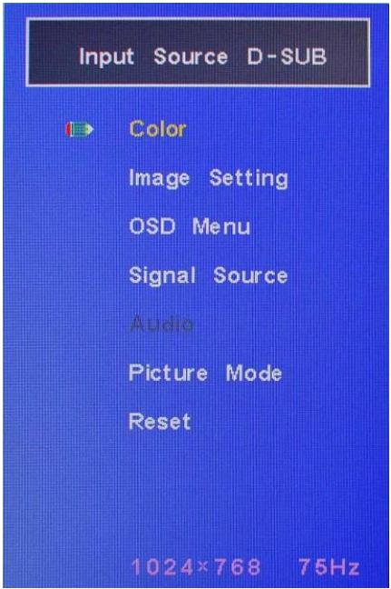
Press the "Menu/Enter" button to bring up the main OSD menu (Figure 5-2). Press "Up" or "Down" to choose the item you wish to set, then press "Menu" to select the item. Use "Up" or "Down" to select the item you wish to set in the submenu, then press "Menu" to select the item. Use "Up" or "Down" to adjust the value, then press "Auto/Source" to return previous page or to exit the OSD menu.
![Input Source D-SUB\nColor\nImage Setting\nOSD Menu\nSignal Source\nAudio\nPicture Mode\nReset\n1024×768 75Hz](.tm-150-50-1z164-1000-010-preliminary-en/e5bdb59e6f563eb222c1b0a7fee03e5ad2198e932193b52b4dc3d69ede50672b.jpg)

Figure 5-2: OSD Main Menu

Table 5.3 shows the structure of OSD menus for the TM Series.

<table><tr><td>Level 1</td><td>Level 2</td><td>Values</td></tr><tr><td rowspan="5">Color</td><td>Contrast</td><td>0 ~ 100</td></tr><tr><td>Brightness</td><td>0 ~ 100</td></tr><tr><td>Color Adjust</td><td>Red, Green, Blue</td></tr><tr><td>Color Temp</td><td>9300, 6500, 5800, User</td></tr><tr><td>Auto Color</td><td>--</td></tr><tr><td rowspan="5">Image Setting</td><td>Clock</td><td>0 ~ 100</td></tr><tr><td>Phase</td><td>0 ~ 100</td></tr><tr><td>Sharpness</td><td>0 ~ 4</td></tr><tr><td>H. Position</td><td>0 ~ 100</td></tr><tr><td>V. Position</td><td>0 ~ 100</td></tr><tr><td rowspan="4">OSD Menu</td><td>OSD H.Pos</td><td>0 ~ 100</td></tr><tr><td>OSD V.Pos</td><td>0 ~ 100</td></tr><tr><td>OSD Timer</td><td>0 ~30 sec.</td></tr><tr><td>Language</td><td>English, French, German, Spanish, Traditional Chinese, Simplified Chinese, Japanese</td></tr><tr><td colspan="2">Signal Source</td><td>D-SUB (VGA), DVI, HDMI, Auto Search</td></tr><tr><td colspan="2">Audio</td><td>Optional</td></tr><tr><td colspan="2">Reset</td><td>Reset to factory settings</td></tr></table>

Table 5-2: OSD Menu Structure

# 5.3 Color Adjustment

Table 5-3 shows the Color Adjustment menu.

![Input Source D-SUB\nContrast\nBrightness\nColor Adjust\nColor Temp\nAuto Color\n50\n1024×768 75Hz](.tm-150-50-1z164-1000-010-preliminary-en/b469ffd09e010ad2166110e3747ef7c8f8682eeb37ac67f14c446d17f71dfd62.jpg)

Figure 5-3: Color Adjustment Menu

▶ Contrast: Adjust the contrast values from 0 to 100
▶ Brightness: Adjust the brightness values from 0 to 100
▶ Color Adjust: Adjust the Color for Red, Green and Blue
▶ Color Temp: Select 9300, 6500, 5800 or User mode for color temperature
▶ Auto Color: Auto adjust the color

# 5.4 Image Settings

Figure 5-4 shows the Image Settings menu.
![Input Source D-SUB\nClock\nPhase\nSharpness\nH. Position\nV. Position\n50\n1024×768 75Hz](.tm-150-50-1z164-1000-010-preliminary-en/f0273e1d657df8ef9c955042563780db4f442a145c2da889eed56aac9bafee60.jpg)

Figure 5-4: Image Setting Menu

▶ Clock: Adjust the Clock values from 0\~100
▶ Phase: Adjust the Phase values from 0\~100
▶ Sharpness: Adjusts the Sharpeness value from 0 to 4
▶ H-Position: Move the screen to right or left from 0\~100
▶ V-Position: Move the screen to up or down from 0\~100

# 5.5 OSD Settings Menu

Figure 5-5 shows the OSD Settings menu.

![Input Source D-SUB\nOSD H. Pos.\nOSD V. Pos.\nOSD Timer\nLanguage\n50\n1024×768 75Hz](.tm-150-50-1z164-1000-010-preliminary-en/dc3482671764a06b4f3860409b02e39e922e634c3a98c104ffc7127508e65057.jpg)

Figure 5-5: OSD Settings Menu

▶ OSD H.Pos: Adjust the OSD horizontal position on the screen
▶ OSD V.Pos: Adjust the OSD vertical position on the screen
▶ OSD Timer: Adjust the time the OSD menu is displayed (0\~30 sec.)
▶ Language: Change the OSD language.

![Input Source D-SUB\nEnglish\nFrançais\nDeutsch\nEspañol\n繁體中文\n簡体中文\n日本語](.tm-150-50-1z164-1000-010-preliminary-en/cc07a3bf8a8ad887ec3376b2bad70da0ea8bd9c50b308f7610835a74d2bed7bb.jpg)

Figure 5-6: OSD Language Menu

# 5.6 Signal Source

Figure 5-7 shows the Signal Source menu.
![Input Source D-SUB\nD-SUB\nDVI\nHDMI\nDisplay Port\nAuto Search\n1024×768 75Hz](.tm-150-50-1z164-1000-010-preliminary-en/8d7b16805f0e52c8f478c5c97e297bea01a9d02793a9550f98f0db67413be9b6.jpg)

Figure 5-7: Signal Source Menu

▶ D-SUB (VGA)
▶ DVI
▶ HDMI
▶ Auto Search

This page intentionally left blank.

# Important Safety Instructions

For user safety, please read and follow all instructions, WARNINGS, CAUTIONS, and NOTES marked in this manual and on the associated equipment before handling/operating the equipment.

▶ Read these safety instructions carefully.
- Keep this user’s manual for future reference.
▶ Read the specifications section of this manual for detailed information on the operating environment of this equipment.
▶ When installing/mounting or uninstalling/removing equipment:

▷ Turn off power and unplug any power cords/cables.

▶ To avoid electrical shock and/or damage to equipment:

▷ Keep equipment away from water or liquid sources;
▷ Keep equipment away from high heat or high humidity;
▷ Keep equipment properly ventilated (do not block or cover ventilation openings);

▶ Make sure to use recommended voltage and power source settings;

▶ Always install and operate equipment near an easily accessible electrical socket-outlet;

▷ Secure the power cord (do not place any object on/over the power cord);

▶ Only install/attach and operate equipment on stable surfaces and/or recommended mountings; and,

▷ If the equipment will not be used for long periods of time, turn off and unplug the equipment from its power source.

▶ Never attempt to fix the equipment. Equipment should only be serviced by qualified personnel.
▶ Equipment must be serviced by authorized technicians when:

▷ The power cord or plug is damaged;
▷ Liquid has penetrated the equipment;
▷ It has been exposed to high humidity/moisture;
$\triangleright$ It is not functioning or does not function according to the user's manual;
▷ It has been dropped and/or damaged; and/or,
▷ It has an obvious sign of breakage.

# Getting Service

Contact us should you require any service or assistance.

# ADLINK Technology, Inc.

Address: 9F, No.166 Jian Yi Road, Zhonghe District
New Taipei City 235, Taiwan
新北市中和區建一路 166 號 9 樓

Tel: +886-2-8226-5877

Fax: +886-2-8226-5717

Email: service@adlinktech.com

# Ampro ADLINK Technology, Inc.

Address: 5215 Hellyer Avenue, #110
San Jose, CA 95138, USA

Tel: +1-408-360-0200

Toll Free: +1-800-966-5200 (USA only)

Fax: +1-408-360-0222

Email: info@adlinktech.com

# ADLINK Technology (China) Co., Ltd.

Address: 上海市浦东新区张江高科技园区芳春路300号(201203)300 Fang Chun Rd., Zhangjiang Hi-Tech Park Pudong New Area, Shanghai, 201203 China

Tel: +86-21-5132-8988

Fax: +86-21-5132-3588

Email: market@adlinktech.com

# ADLINK Technology Beijing

Address: 北京市海淀区上地东路 1 号盈创动力大厦 E 座 801 室(100085)
Rm. 801, Power Creative E, No. 1 Shang Di East Rd.
Beijing, 100085 China

Tel: +86-10-5885-8666

Fax: +86-10-5885-8626

Email: market@adlinktech.com

# ADLINK Technology Shenzhen

Address: 深圳市南山区科技园南区高新南七道 数字技术园
A1 栋 2 楼 C 区 (518057)
2F, C Block, Bldg. A1, Cyber-Tech Zone, Gao Xin Ave. Sec. 7
High-Tech Industrial Park S., Shenzhen, 518054 China

Tel: +86-755-2643-4858

Fax: +86-755-2664-6353

Email: market@adlinktech.com

# LiPPERT ADLINK Technology GmbH

Address: Hans-Thoma-Strasse 11, D-68163
Mannheim, Germany

Tel: +49-621-43214-0

Fax: +49-621 43214-30

Email: emea@adlinktech.com

# ADLINK Technology, Inc. (French Liaison Office)

Address: 6 allée de Londres, Immeuble Ceylan
91940 Les Ulis, France

Tel: +33 (0) 1 60 12 35 66

Fax: +33 (0) 1 60 12 35 66

Email: france@adlinktech.com

# ADLINK Technology Japan Corporation

Address: 〒101-0045 東京都千代田区神田鍛冶町 3-7-4
神田 374 ビル 4F
KANDA374 Bldg. 4F, 3-7-4 Kanda Kajicho,
Chiyoda-ku, Tokyo 101-0045, Japan

Tel: +81-3-4455-3722

Fax: +81-3-5209-6013

Email: japan@adlinktech.com

# ADLINK Technology, Inc. (Korean Liaison Office)

Address: 137-881 서울시 서초구 서초대로 326, 802 (서초동, 모인터빌딩)
802, Mointer B/D, 326 Seocho-daero, Seocho-Gu,
Seoul 137-881, Korea

Tel: +82-2-2057-0565

Fax: +82-2-2057-0563

Email: korea@adlinktech.com

# ADLINK Technology Singapore Pte. Ltd.

Address: 84 Genting Lane #07-02A, Cityneon Design Centre Singapore 349584

Tel: +65-6844-2261

Fax: +65-6844-2263

Email: singapore@adlinktech.com

# ADLINK Technology Singapore Pte. Ltd. (Indian Liaison Office)

Address: #50-56, First Floor, Spearhead Towers Margosa Main Road (between 16th/17th Cross) Malleswaram, Bangalore - 560 055, India

Tel: +91-80-65605817, +91-80-42246107

Fax: +91-80-23464606

Email: india@adlinktech.com

# ADLINK Technology, Inc. (Israeli Liaison Office)

Address: 27 Maskit St., Corex Building
PO Box 12777
Herzliya 4673300, Israel

Tel: +972-77-208-0230

Fax: +972-77-208-0230

Email: israel@adlinktech.com

# ADLINK Technology, Inc. (UK Liaison Office)

Tel: +44 774 010 59 65

Email: UK@adlinktech.com
[🔗 Link to the original document](.tm-150-50-1z164-1000-010-preliminary-en/tm-150-50-1z164-1000-010-preliminary-en.pdf)
