![Abstract geometric design with overlapping colored triangles and a stylized checkmark (no text or symbols)](.vortex-opensplice-dds-labview-guide/8b0df418fdf520ad851b5a39f23ca9c8fb8e2b2fb40e41348e6d8ca8c9892543.jpg)

# ORTEX

# OpenSplice LabVIEW Guide

Release 6.x

# Contents

# 1 Introduction 1

1.1 DDS
1.2 LabVIEW 2

# 2 Installation 3

2.1 System Requirements 3
2.2 OpenSplice (OSPL) and DDS LabVIEW Installation 3
2.3 OpenSplice (OSPL) Configuration . 3
2.4 DDS LabVIEW Installation 3

2.4.1 Linux 3
2.4.2 Windows 4

2.5 Running LabVIEW . 5

# 3 Vortex DDS Virtual Instruments (VIs) 6

3.1 DDS VIs usage 6
3.2 QoS Profiles 7
3.3 create\_participant.vi 7
3.4 create\_publisher.vi 8
3.5 create\_subscriber.vi 9
3.6 create\_writer.vi 9
3.7 create\_reader.vi 10
3.8 wait\_historical\_data.vi 10
3.9 delete\_entity.vi 11

# 4 LabVIEW Generation from IDL 12

4.1 Generating LabVIEW VIs from an IDL File IDLPP 12
4.2 Generated Artifacts . 14
4.3 RegisterTopic.vi 15
4.4 Read.vi 16

4.4.1 Filters 17

4.5 Write.vi . 18

# 5 QoS Provider 19

5.1 QoS Provider File 19
5.2 QoS Profile 19
5.3 Setting QoS Profile in LabVIEW 20

# 6 Demo iShapes Example 22

6.1 Example Files 23
6.2 Steps to run example 25
6.3 Output 27

# 7 Contacts & Notices 28

7.1 Contacts 28
7.2 Notices 28

# 1

# Introduction

The DDS LabVIEW Integration provides users with DDS custom virtual instruments (VIs) to model DDS communication between LabVIEW and pure DDS applications.

# 1.1 DDS

# What is DDS?

“The Data Distribution Service (DDS™) is a middleware protocol and API standard for data-centric connectivity from the Object Management Group® (OMG®). It integrates the components of a system together, providing low-latency data connectivity, extreme reliability, and a scalable architecture that business and mission-critical Internet of Things (IoT) applications need.”

“The main goal of DDS is to share the right data at the right place at the right time, even between time-decoupled publishers and consumers. DDS implements global data space by carefully replicating relevant portions of the logically shared dataspace.” DDS specification

![**Labeled Blocks:**\n*   **Data-Object** (oval shape at the top center)\n*   **Publisher** (rectangle in the left box)\n*   **DataWriter** (rectangle in the left box)\n*   **Subscriber** (rectangle in the top right box)\n*   **DataReader** (rectangle in the top right box)\n*   **Subscriber** (rectangle in the bottom right box)\n*   **DataReader** (rectangle in the bottom right box)\n\n**Connections:**\n*   **DataWriter** connects to **Publisher** with a solid arrow labeled 'data values'.\n*   **Publisher** connects to the top **Subscriber** with a dashed line labeled 'dissemination'.\n*   **Publisher** connects to the bottom **Subscriber** with a dashed line (extending downwards from the Publisher area).\n*   The top **Subscriber** connects to the top **DataReader** with a solid arrow labeled 'data values'.\n*   The bottom **Subscriber** connects to the bottom **DataReader** with a solid arrow labeled 'data values'.\n*   The left box (containing **Publisher** and **DataWriter**) connects to **Data-Object** with a dashed line labeled 'Identified by means of the Topic'.\n*   The bottom right **DataReader** connects to **Data-Object** with a dashed line labeled 'Identified by means of the Topic'.](.vortex-opensplice-dds-labview-guide/7c24e4cc2c12e1e27527fafea2186a10e177cdb597ac8743ef69cc020bcfbd13.jpg)

# Further Documentation

http://portals.omg.org/dds/

http://ist.adlinktech.com/

# 1.2 LabVIEW

# What is LabVIEW?

“LabVIEW is systems engineering software for applications that require test, measurement, and control with rapid access to hardware and data insights. The LabVIEW programming environment simplifies hardware integration for engineering applications so that you have a consistent way to acquire data from NI and third-party hardware. The LabVIEW programming environment simplifies hardware integration for engineering applications so that you have a consistent way to acquire data from NI and third-party hardware. LabVIEW reduces the complexity of programming, so you can focus on your unique engineering problem. LabVIEW enables you to immediately visualize results with built-in, drag-and-drop engineering user interface creation and integrated data viewers. To turn your acquired data into real business results, you can develop algorithms for data analysis and advanced control with included math and signal processing IP or reuse your own libraries from a variety of tools. To ensure compatibility with other engineering tools, LabVIEW can interoperate with, and reuse libraries from, other software and open-source languages.”

http://www.ni.com/en-ca/shop/labview/buy-labview.html

# 2

# Installation

This section describes the procedure to install the Vortex DDS LabVIEW Integration on a Linux or Windows platform.

# 2.1 System Requirements

• Operating System: Windows or Linux
• LabVIEW 2017 installed

# 2.2 OpenSplice (OSPL) and DDS LabVIEW Installation

# Steps:

1. Install OSPL. The DDS LabVIEW Integration is included in this installer.
2. Setup OSPL license. Copy the license.lic file into the appropriate license directory. /INSTALLDIR/ADLINK/Vortex\_v2/license
3. LabVIEW installation files are contained in a tools/labview folder.

Example: /INSTALLDIR/ADLINK/Vortex\_v2/Device/VortexOpenSplice/6.9.x/HDE/x86\_64.linux/tools/labview

# 2.3 OpenSplice (OSPL) Configuration

By default OSPL uses single process configuration.

# 2.4 DDS LabVIEW Installation

# 2.4.1 Linux

1. Open a command shell and navigate to /INSTALLDIR/ADLINK/Vortex\_v2/Device/VortexOpenSplice/6.9.x/HDE/x86\_64.linux/tools/labview
2. Unzip the “adlink-dds-labview-linux-install.tar.gz”.
3. Run the install\_vortex\_dds\_ubuntu.sh script as a super user. sudo ./install\_vortex\_dds\_ubuntu.sh

NOTE: The installer sets the default LabVIEW installation path to /usr/local/natinst/LabVIEW-2017-64. To override this installation directory, run the install script and pass the install directory as an argument: sudo ./install\_vortex\_dds\_ubuntu.sh /path/to/your/LabVIEW/installation

4. LabVIEW will open and allow the installation Virtual Instrument (VI) run to completion.
5. After the installation is complete close LabVIEW. Installation takes effect the next time you start LabVIEW.

# 2.4.2 Windows

1. In a file browser, navigate to

/INSTALLDIR/ADLINK/Vortex\_v2/Device/VortexOpenSplice/6.9.x/HDE/x86\_64.windows/tools/labview

2. Double click on the file “adlink\_lib\_vortexdds-1.0.0.1”. This will bring up the VI Package Manager installer dialog box. Select the LabVIEW version to install (32-bit or 64-bit). Select Install.

![JKI VIPM - VortexDDS\nFile Help\nPackage Information\nSelect an action to perform on the package.\n2017\nInstall\nShow in Palettes\nShow Examples\n*Upgrade available\nClick to show\n*Browse All Versions\nVortexDDS v1.0.0.1 by ADLINK\nAuthor: adlinktech\nCopyright: Copyright (c) 2017, ADLINK Technology Limited\nCompatible LabVIEW Versions: )= 2017.\nCompatible OS Versions: ALL.](.vortex-opensplice-dds-labview-guide/2ae29100f204cc740a7da07971f0ff2655779c8369df0c2efe49cf847f2372ea.jpg)

3. After the installation is complete close LabVIEW. Installation takes effect the next time you start LabVIEW.

# 2.5 Running LabVIEW

# Steps:

1. Open command shell and run script to setup environment variables.

# Linux

• Open a Linux terminal.
• Navigate to directory containing release.com file.
/INSTALLDIR/ADLINK/Vortex\_v2/Device/VortexOpenSplice/6.9.x/HDE/x86\_64.linux
• Run release.com. (Type in “. release.com” at command line.)

# Windows

• Open a command prompt.
• Navigate to directory containing release.bat file.
INSTALLDIR/ADLINK/Vortex\_v2/Device/VortexOpenSplice/6.9.x/HDE/x86\_64.win64
• Run release.bat. (Type in “release.bat” at command line.)

2. Start LabVIEW using the SAME command shell used in Step 1.

NOTE: If LabVIEW is NOT started from a command shell with the correct OSPL environment variables set, errors will occur when attempting to use DDS LabVIEW virtual instruments.

# 3

# Vortex DDS Virtual Instruments (VIs)

The DDS LabVIEW Integration provides a function palette with custom virtual instruments (VIs) to model reading and writing data with DDS.

![vortex_dds_blocks\ncreate_participat...\ncreate_publisher\ncreate_reader\ncreate_subscri...\ncreate_writer\ndelete_entity\nwait_historical...](.vortex-opensplice-dds-labview-guide/b802593ef212bf0c37433f3fb0014c3e8fab453b3573efe389ef4ba696dc5a98.jpg)

The Vortex DDS LabVIEW VIs are included in VortexDDS functions palette.

The following DDS VIs are provided:

• create\_participant.vi
• create\_publisher.vi
• create\_subscriber.vi
• create\_writer.vi
• create\_reader.vi
• wait\_historical\_data.vi
• delete\_entity.vi

# 3.1 DDS VIs usage

The typical way to model a DDS application in LabVIEW is as follows:

• model your DDS topics using IDL
• using the LabVIEW IDLPP process generate DDS Topic, Read and Write VIs from the IDL file
• add the generated VIs to your LabVIEW project
• create a DDS LabVIEW application using the VortexDDS functions palette and the generated VIs from the previous step

# 3.2 QoS Profiles

In DDS - “The Data-Distribution Service (DDS) relies on the usage of QoS. A QoS (Quality of Service) is a set of characteristics that controls some aspect of the behavior of the DDS Service.”

Each DDS entity VI has an associated QoS profile. By default, the OSPL default profile is used. An XML file that specifies QoS profiles can be used to set the QoS of a DDS entity.

The QoS profile of an entity is set using the qos\_uri and qos\_profile terminals.

Please see section QoS Provider for more information.

# 3.3 create\_participant.vi

The create\_participant VI represents a DDS domain participant entity.

In DDS - “A domain participant represents the local membership of the application in a domain. A domain is a distributed concept that links all the applications able to communicate with each other. It represents a communication plane: only the publishers and subscribers attached to the same domain may interact.”

The domain id is the OSPL default domain id specified in the OSPL configuration file (file pointed by “OSPL\_URI” environment variable).

![This diagram displays a VI (Virtual Instrument) block titled **vortex_dds_blocks.lvlib:create_participant.vi**.\n\n**Input Terminals (Left Side):**\n*   **qos_uri**: Connected via a cyan wavy line.\n*   **qos_profile**: Connected via a pink wavy line.\n*   **error in (no error)**: Connected via a yellow dashed line.\n\n**Output Terminals (Right Side):**\n*   **pp**: Connected via a blue solid line.\n*   **error out**: Connected via a yellow dashed line.\n\nThe block icon features a blue rectangle at the top and a white square below containing a green circle.](.vortex-opensplice-dds-labview-guide/ca799e432a16ad5b86c09695729d703aef3bf0f7e2db309fec28efa984033ef3.jpg)

<table><tr><td>Terminal Type</td><td>Op-tional</td><td>Name</td><td>Description</td><td>Output consumed by</td></tr><tr><td>Output</td><td>no</td><td>pp</td><td>DDS Domain Participant entity instance</td><td>create_publisher.vi create_subscriber.vi RegisterTopic.vi</td></tr><tr><td>Input</td><td>yes</td><td>qos_uri</td><td>QoS file uri</td><td></td></tr><tr><td>Input</td><td>yes</td><td>qos_profile</td><td>Name of QoS profile</td><td></td></tr><tr><td>Input</td><td>yes</td><td>error in (no error)</td><td>Input Error cluster</td><td></td></tr><tr><td>Output</td><td>yes</td><td>error out</td><td>Error out cluster</td><td></td></tr></table>

# 3.4 create\_publisher.vi

The create\_publisher VI represents a DDS publisher entity.

In DDS, a publisher is “an object responsible for data distribution. It may publish data of different data types.”

![This image shows a LabVIEW block diagram snippet.\n\n**Central Block:**\nA function node (VI call) located in the center. Above it is the text label:\n`vortex_dds_blocks.lvlib:create_publisher.vi`\n\n**Input Connections (Left Side):**\n- `PP` (connected via a blue wire to the top terminal)\n- `qos_uri` (connected via a teal wavy wire to the second terminal)\n- `qos_profile` (connected via a pink wavy wire to the third terminal)\n- `error in (no error)` (connected via a yellow dashed wire to the bottom terminal)\n\n**Output Connections (Right Side):**\n- `pub` (connected via a blue wire from the top terminal)\n- `error out` (connected via a yellow dashed wire from the bottom terminal)](.vortex-opensplice-dds-labview-guide/c2b3651ba1e22c555cdfb65f75174b35e8afce7d8dc64727dac541f6107674e9.jpg)

<table><tr><td>Terminal Type</td><td>Optional</td><td>Name</td><td>Description</td><td>Output consumed by</td></tr><tr><td>Input</td><td>no</td><td>pp</td><td>DDS Domain Participant entity instance</td><td></td></tr><tr><td>Input</td><td>yes</td><td>qos_uri</td><td>QoS file uri</td><td></td></tr><tr><td>Input</td><td>yes</td><td>qos_profile</td><td>Name of QoS profile</td><td></td></tr><tr><td>Input</td><td>yes</td><td>error in (no error)</td><td>Input Error cluster</td><td></td></tr><tr><td>Output</td><td>no</td><td>pub</td><td>DDS publisher entity instance</td><td>create_writer.vi</td></tr><tr><td>Output</td><td>yes</td><td>error out</td><td>Error out cluster</td><td></td></tr></table>

# 3.5 create\_subscriber.vi

The create\_subscriber VI represents a DDS subscriber entity.

In DDS, a subscriber is “an object responsible for receiving published data and making it available to the receiving application. It may receive and dispatch data of different specified types.”

![The diagram displays a block titled **create_subscriber.vi**.\n\n**Central Block:**\nA rectangular node with a blue top section and a white bottom section containing a blue arrow pointing to the left.\n\n**Connections (Inputs - Left Side):**\n*   **pp**: Connected via a solid blue wire.\n*   **qos_uri**: Connected via a dashed teal wire.\n*   **qos_profile**: Connected via a dashed pink wire.\n*   **error in (no error)**: Connected via a dotted yellow wire.\n\n**Connections (Outputs - Right Side):**\n*   **sub**: Connected via a solid blue wire.\n*   **error out**: Connected via a dotted yellow wire.](.vortex-opensplice-dds-labview-guide/d0ffc33372e5d890b58e1a2ea258bf2469de4c1a299ba29b99b3ab006eb1531c.jpg)

<table><tr><td>Terminal Type</td><td>Optional</td><td>Name</td><td>Description</td><td>Output consumed by</td></tr><tr><td>Input</td><td>no</td><td>pp</td><td>DDS Domain Participant entity instance</td><td></td></tr><tr><td>Input</td><td>yes</td><td>qos_uri</td><td>QoS file uri</td><td></td></tr><tr><td>Input</td><td>yes</td><td>qos_profile</td><td>Name of QoS profile</td><td></td></tr><tr><td>Input</td><td>yes</td><td>error in (no error)</td><td>Input Error cluster</td><td></td></tr><tr><td>Output</td><td>no</td><td>sub</td><td>DDS subscriber entity instance</td><td>create_reader.vi</td></tr><tr><td>Output</td><td>yes</td><td>error out</td><td>Error out cluster</td><td></td></tr></table>

# 3.6 create\_writer.vi

The create\_writer VI represents a DDS data writer entity.

In DDS - “The DataWriter is the object the application must use to communicate to a publisher the existence and value of data-objects of a given type.”

![The diagram displays a function node labeled **create_writer.vi**.\n\n**Labeled Blocks/Terminals:**\n*   **create_writer.vi** (The central rectangular block with a purple top bar and a pencil icon)\n*   **qos_profile**\n*   **pub**\n*   **topic**\n*   **qos_uri**\n*   **error in (no error)**\n*   **writer**\n*   **error out**\n\n**Connections:**\n*   **qos_profile** connects to the top input of the block.\n*   **pub** connects to the second input.\n*   **topic** connects to the third input.\n*   **qos_uri** connects to the fourth input.\n*   **error in (no error)** connects to the bottom input (indicated by a dashed yellow line).\n*   **writer** connects from the second output.\n*   **error out** connects from the bottom output (indicated by a dashed yellow line).](.vortex-opensplice-dds-labview-guide/8b8f8b0ed7406ad9ae2ee1eaf29f89eb25566c3dfeed6d9fc61767a6914c45dd.jpg)

<table><tr><td>Terminal Type</td><td>Optional</td><td>Name</td><td>Description</td><td>Output consumed by</td></tr><tr><td>Input</td><td>no</td><td>pub</td><td>DDS publisher entity instance</td><td></td></tr><tr><td>Input</td><td>no</td><td>topic</td><td>DDS Topic entity instance</td><td></td></tr><tr><td>Input</td><td>yes</td><td>qos_uri</td><td>QoS file uri</td><td></td></tr><tr><td>Input</td><td>yes</td><td>qos_profile</td><td>Name of QoS profile</td><td></td></tr><tr><td>Input</td><td>yes</td><td>error in (no error)</td><td>Input Error cluster</td><td></td></tr><tr><td>Output</td><td>no</td><td>writer</td><td>DDS writer entity instance</td><td>write.vi</td></tr><tr><td>Output</td><td>yes</td><td>error out</td><td>Error out cluster</td><td></td></tr></table>

# 3.5. create\_subscriber.vi

# 3.7 create\_reader.vi

The create\_reader VI represents a DDS data reader entity.

In DDS - “To access the received data, the application must use a typed DataReader attached to the subscriber.”

![This diagram depicts a LabVIEW block for a VI named **create_reader.vi**. It features a central rectangular block with a blue top section and a white bottom section containing a glasses icon (inspection tunnel).\n\n**Inputs (Left Side):**\n*   **qos_profile**: Connected via a pink dashed line to the top input of the block.\n*   **sub**: Connected via a blue line to the middle input.\n*   **topic**: Connected via a blue line to the input directly below 'sub'.\n*   **qos_uri**: Connected via a teal zig-zag line to the bottom input.\n*   **error in (no error)**: Connected via a yellow zig-zag line to the bottom-left error input terminal.\n\n**Outputs (Right Side):**\n*   **reader**: Connected via a blue line exiting the right side.\n*   **error out**: Connected via a yellow zig-zag line exiting the bottom-right corner.](.vortex-opensplice-dds-labview-guide/8953ee3a4b1138502168485b7095530823ebd4ada2b65456c29db1bda567945e.jpg)

<table><tr><td>Terminal Type</td><td>Optional</td><td>Name</td><td>Description</td><td>Output consumed by</td></tr><tr><td>Input</td><td>no</td><td>sub</td><td>DDS subscriber entity instance</td><td></td></tr><tr><td>Input</td><td>no</td><td>topic</td><td>DDS Topic entity instance</td><td></td></tr><tr><td>Input</td><td>yes</td><td>qos_uri</td><td>QoS file uri</td><td></td></tr><tr><td>Input</td><td>yes</td><td>qos_profile</td><td>Name of QoS profile</td><td></td></tr><tr><td>Input</td><td>yes</td><td>error in (no error)</td><td>Input Error cluster</td><td></td></tr><tr><td>Output</td><td>no</td><td>reader</td><td>DDS reader entity instance</td><td>read.vi</td></tr><tr><td>Output</td><td>yes</td><td>error out</td><td>Error out cluster</td><td></td></tr></table>

# 3.8 wait\_historical\_data.vi

The wait\_historical\_data VI specifies that the Reader will wait for historical data to arrive. The timeout terminal is for setting time period (in seconds) determining how long the Reader should wait for the historical data. If the timeout is reached, then any remaining historical data may be interleaved with new data.

![The diagram depicts a block titled **wait_historical_data.vi**.\n\n**Central Block:**\nA rectangular node featuring a blue top section and a white bottom section containing an hourglass icon.\n\n**Connections:**\n*   **Inputs (Left side):**\n    *   A blue wire labeled **reader** connects to the top of the block.\n    *   An orange wire labeled **historical_timeout** connects to the middle of the block.\n    *   A yellow wire labeled **error in (no error)** connects to the bottom of the block.\n*   **Output (Right side):**\n    *   A yellow wire labeled **error out** exits from the right side of the block.](.vortex-opensplice-dds-labview-guide/d6065366a4071c09f8bae4cfd56664a50e64406e8f2d24c152ad892e61e60ab0.jpg)

<table><tr><td>Terminal Type</td><td>Optional</td><td>Name</td><td>Description</td><td>Output consumed by</td></tr><tr><td>Input</td><td>no</td><td>reader</td><td>DDS Reader entity instance</td><td></td></tr><tr><td>Input</td><td>yes</td><td>histori-cal_timeout</td><td>wait for historical data timeout (seconds)</td><td></td></tr><tr><td>Input</td><td>yes</td><td>error in (no error)</td><td>Input Error cluster</td><td></td></tr><tr><td>Output</td><td>yes</td><td>error out</td><td>Error out cluster</td><td></td></tr></table>

# 3.9 delete\_entity.vi

The delete\_entity VI is used to delete a DDS entity. Connect the DDS participant to the entity terminal to delete the participant (pp) in a LabVIEW DDS application.

NOTE: If the user application VI stops due to an error and does not run to completion, the participant entity is not deleted and leaks occur. The participants are deleted once the user closes LabVIEW.

![Context Help\ndelete_entity.vi\nentity\nX](.vortex-opensplice-dds-labview-guide/b0e400fabbffe6856b397668d9f6279ef1637e56b2322b97d1513d945b4cfd32.jpg)

<table><tr><td>Terminal Type</td><td>Optional</td><td>Name</td><td>Description</td><td>Output consumed by</td></tr><tr><td>Input</td><td>no</td><td>entity</td><td>DDS entity instance</td><td></td></tr></table>

# 4

# LabVIEW Generation from IDL

While creating a DDS application in LabVIEW, the user must create Topic VIs which map to DDS topic types. In addition to registering a topic, the user neeeds to create DDS Read and DDS Write VIs. LabVIEW data is represented in clusters. The DDS Read and Write VIs have terminals that require a LabVIEW cluster. On data writes, the LabVIEW clusters are converted to DDS topic types and on data reads, the DDS topic types are converted to LabVIEW clusters.

The user can generate the LabVIEW clusters and DDS VIs from an IDL file.

The DDS LabVIEW Integration supports generation of LabVIEW typedefs and VIs from IDL. This chapter describes the details of the IDL-LabVIEW binding.

# 4.1 Generating LabVIEW VIs from an IDL File IDLPP

DDS Topic Types can be described in an IDL file. The LabVIEW IDL generation is done using the Import\_IDL Tools menu in LabVIEW.

Tools/VortexDDS/Import\_IDL

![Tools Window Help\nMeasurement & Automation Explorer...\nInstrumentation ▶\nProfile ▶\nSecurity ▶\nUser Name...\nInformation on Building Applications\nLLB Manager...\nImport ▶\nShared Variable ▶\nDistributed System Manager\nFind VIs on Disk...\nPrepare Example VIs for NI Example Finder...\nRemote Panel Connection Manager...\nWeb Publishing Tool...\nFind LabVIEW Add-ons...\nVI Package Manager...\nVortexDDS ▶ Import_IDL...\nAdvanced ▶ List_qos_profiles...\nOptions...](.vortex-opensplice-dds-labview-guide/df8a4eca41399706adca549a24278a4490caf3b17af2129d8be28d69f904c309.jpg)

In the IDL file, ensure that any topic structures have the OSPL specific annotation pragma keylist defined. This value is added as a keylist constant to the key terminal of the generated RegisterTopic.vi.

Select the IDL file and a folder for the generated VIs.

![IDL VI Generator\nIDLPP VI Generator:\nSelect the IDL File to create VIs for\n- registering Topics\n- generating Topic Clusters and Enums\n- writing to the Topic\n- reading from the Topic\n\nPath to IDL File\nC:\LabVIEW Test\ShapesTest.idl\n\nTarget Directory for generated VIs\nC:\LabVIEW Test\generated VIs\n\nOK	Cancel](.vortex-opensplice-dds-labview-guide/7e8bff67bdca5a563ff9bd315355f39250a1ace7e6c16673c126af5519b175c7.jpg)

Upon successful generation the VIs are located in the folder that was chosen. A dialog box appears indicating the path of the generated VIs and the IDL file.

![IDL Import Success\nSuccessfully generated Vls\nIDL File: ShapesTest.idl\nTarget Directory: C:\LabVIEW Test\generated Vls\nOK](.vortex-opensplice-dds-labview-guide/1b9ed802ff240b2d432c95b87614ad62d8c2197a0253cfe2b4f757560a259b16.jpg)

# 4.2 Generated Artifacts

The following table defines the LabVIEW artifacts generated from IDL concepts:

<table><tr><td>IDL Concept</td><td>LabVIEW Concept</td><td>Comment</td></tr><tr><td>module</td><td></td><td>Appended to the name of each VI contained in the module</td></tr><tr><td>enum</td><td>enum</td><td>a LabVIEW .ctl file.</td></tr><tr><td>enum value</td><td>enum value</td><td></td></tr><tr><td>struct</td><td>cluster</td><td>a LabVIEW .ctl file.</td></tr><tr><td>field</td><td>cluster field</td><td></td></tr><tr><td>sequence</td><td>array</td><td></td></tr><tr><td>array</td><td>array</td><td></td></tr></table>

# Datatype mappings

The following table shows the LabVIEW equivalents to IDL primitive types:

<table><tr><td>DDS IDL</td><td>LabVIEW Type</td></tr><tr><td>boolean</td><td>Boolean</td></tr><tr><td>char</td><td>int8</td></tr><tr><td>octet</td><td>uint8</td></tr><tr><td>short</td><td>int16</td></tr><tr><td>unsigned short</td><td>uint16</td></tr><tr><td>long</td><td>int32</td></tr><tr><td>unsigned long</td><td>uint32</td></tr><tr><td>long long</td><td>int64</td></tr><tr><td>unsigned long long</td><td>uint64</td></tr><tr><td>float</td><td>single-precision floating point</td></tr><tr><td>double</td><td>double-precision floating point</td></tr><tr><td>string</td><td>String</td></tr><tr><td colspan="2">Unsupported DDS data types</td></tr><tr><td>wchar</td><td>not supported</td></tr><tr><td>wstring</td><td>not supported</td></tr><tr><td>any</td><td>not supported</td></tr><tr><td>long double</td><td>not supported</td></tr><tr><td>union</td><td>not supported</td></tr><tr><td>inheritance</td><td>not supported</td></tr></table>

# Generated VIs and controls

For each struct in the IDL file, the following VIs and controls are generated:

• RegisterTopic.vi
• Write.vi
• Read.vi
• CicoTable.vi (Copy-in copy-out)
• Topic cluster.ctl (corresponds to each struct in IDL File)
• Enum.ctl (corresponds to each enum in IDL File)

The “moduleName\_structName” is appended to the name of each VI and control that is generated.

# 4.3 RegisterTopic.vi

The RegisterTopic.vi represents a DDS topic type. The DDS topic corresponds to a single data type. In DDS, data is distributed by publishing and subscribing topic data samples.

![Based on the image provided, here is an accurate and concise description of the flowchart/block diagram:\n\n**Central Node:**\nA functional block labeled **REGISTER TOPIC** (split into a black upper box and a white lower box with the text).\n\n**Input Terminals (Left Side):**\n*   **QoSProfilePath (4)**: Connected via a blue zigzag wire.\n*   **DomainParticipantHandle (0)**: Connected via a blue straight wire.\n*   **TopicName (1)**: Connected via a pink zigzag wire.\n*   **QoSProfileName (2)**: Connected via a pink zigzag wire.\n*   **error in (no error) (3)**: Connected via a yellow dotted wire.\n\n**Output Terminals (Right Side):**\n*   **(5) topicHandle**: Connected via a blue straight wire.\n*   **(6) error out**: Connected via a yellow dotted wire.](.vortex-opensplice-dds-labview-guide/1161b245ea513d536a5c98b0a891a20a0cf148e86803f84f489d5c2e6c75965c.jpg)

<table><tr><td>Terminal Type</td><td>Optional</td><td>Name</td><td>Description</td><td>Output consumed by</td></tr><tr><td>Input</td><td>no</td><td>DomainParticipantHandle</td><td>DDS Domain Participant entity instance</td><td></td></tr><tr><td>Input</td><td>no</td><td>TopicName</td><td>DDS Topic Name</td><td></td></tr><tr><td>Input</td><td>yes</td><td>QosProfilePath</td><td>QoS file uri</td><td></td></tr><tr><td>Input</td><td>yes</td><td>QoSProfileName</td><td>Name of QoS profile</td><td></td></tr><tr><td>Input</td><td>yes</td><td>error in (no error)</td><td>Input Error cluster</td><td></td></tr><tr><td>Output</td><td>no</td><td>topicHandle</td><td>DDS Topic entity instance</td><td>create_reader.vi create_writer.vi</td></tr><tr><td>Output</td><td>yes</td><td>error out</td><td>Error out cluster</td><td></td></tr></table>

# 4.4 Read.vi

The DDS Read.vi is used to read DDS samples from a specific topic.

![Based on the provided image, here is the accurate and concise description of the block diagram:\n\n**Title:** Shapes__ShapeType_Read.vi (4815)\n\n**Central Block:**\nA rectangular node (likely a LabVIEW subVI or function) containing the stacked text:\n*   DDS\n*   READ\n*   FRAME (or similar text, partially obscured but 'DDS READ' is clear)\n*   (Note: The bottom of the block has the number '7')\n\n**Left Terminals (Inputs):**\n*   `query_expression (5)`\n*   `mask (7)`\n*   `readerHandle (11)`\n*   `max_samples (10)`\n*   `read_operation (9)`\n*   `error in (no error) (8)`\n*   `wait_available_data_timeout (6)`\n*   `query_parameters (4)`\n\n**Right Terminals (Outputs):**\n*   `(3) no_of_samples`\n*   `(2) samples`\n*   `(1) dds_sample_info_array`\n*   `(0) error out`\n\n**Connections:**\nColored wires connect the left terminals to the central block and the right terminals to the central block, indicating data flow.\n*   **Pink dotted wires** connect: `query_expression (5)`, `mask (7)`, `query_parameters (4)`, `(2) samples`, and `(1) dds_sample_info_array`.\n*   **Blue solid wires** connect: `readerHandle (11)`, `max_samples (10)`, and `(3) no_of_samples`.\n*   **Yellow dotted wires** connect: `read_operation (9)`, `error in (no error) (8)`, and `(0) error out`.\n*   **Orange solid wire** connects: `wait_available_data_timeout (6)`.](.vortex-opensplice-dds-labview-guide/597c7e81b4e523e2d4f009e0556df30d3b941790707dcef1716edda47ecc4179.jpg)

<table><tr><td>Terminal Type</td><td>Optional</td><td>Name</td><td>Description</td><td>Output consumed by</td></tr><tr><td>Input</td><td>no</td><td>readerHandle</td><td>DDS Reader entity instance</td><td></td></tr><tr><td>Input</td><td>yes</td><td>mask</td><td>read_condition masks LabVIEW cluster</td><td></td></tr><tr><td>Input</td><td>yes</td><td>max_samples</td><td>maximum number of samples to read</td><td></td></tr><tr><td>Input</td><td>yes</td><td>read_operation</td><td>READ or TAKE default operation is TAKE</td><td></td></tr><tr><td>Input</td><td>yes</td><td>query_expression</td><td>expression to filter samples based on a query</td><td></td></tr><tr><td>Input</td><td>yes</td><td>query_parameters</td><td>parameters for the query expression</td><td></td></tr><tr><td>Input</td><td>yes</td><td>wait_available_data _timeout</td><td>wait for data available timeout (seconds)</td><td></td></tr><tr><td>Input</td><td>yes</td><td>error in (no error)</td><td>Input Error cluster</td><td></td></tr><tr><td>Output</td><td>yes</td><td>no_of_samples</td><td>Number of samples read</td><td>user</td></tr><tr><td>Output</td><td>no</td><td>samples</td><td>LabVIEW cluster</td><td>user</td></tr><tr><td>Output</td><td>yes</td><td>dds_sample_info_array</td><td>sample information</td><td>user</td></tr><tr><td>Output</td><td>yes</td><td>error out</td><td>Error out cluster</td><td></td></tr></table>

# 4.4.1 Filters

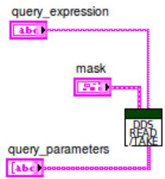
The filtering of incoming samples can happen based on a query and/or on a sample read condition(s).

# Query

query\_expression: The expression is a SQL condition.

query\_parameters: Each parameter element must be an array element.

Note: Query expressions are only validated at runtime. If they are incorrect, errors will occur while running the VI.

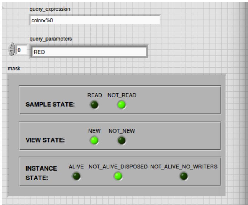
# Read Condition

The read condition mask specified will filter the samples that are read or take(n).

Example: For a reader, the Sample State has Not Read selected and Read deselected.

Only samples with a Sample State Not Read will be processed with read or take. Any samples with the Read sample state will not be read or take(n).
![query_expression\ncolor=%0\nquery_parameters\n0 RED\nmask\nSAMPLE STATE: READ NOT_READ\nVIEW STATE: NEW NOT_NEW\nINSTANCE ALIVE NOT_ALIVE_DISPOSED NOT_ALIVE_NO_WRITERS\nSTATE:](.vortex-opensplice-dds-labview-guide/0e0f7b97795bfa35542bbfa94ccc4a4d5283e3ca0e6a2f59622114831d4e1998.jpg)

![Based on the provided image, here is the accurate description of the flowchart:\n\n**Labeled Blocks:**\n*   **query_expression**: A label positioned above a box containing the text `(abc)`.\n*   **mask**: A label positioned above a box containing the text `(FS)`.\n*   **query_parameters**: A label positioned above a box containing the text `(abc)`.\n*   **DDS MAP TAKE**: A large green rectangular box containing stacked white text.\n\n**Connections:**\n*   A dashed pink line originates from the right side of the `(abc)` box (under `query_expression`), travels right, then turns 90 degrees up.\n*   A dashed pink line originates from the right side of the `(FS)` box (under `mask`), travels right, then turns 90 degrees up. This line merges with the vertical line coming from the `query_expression` block.\n*   This combined vertical dashed line runs down the right side of the diagram and connects to the right side of the `DDS MAP TAKE` box.\n*   A dashed pink line originates from the right side of the `(abc)` box (under `query_parameters`), travels right, then turns 90 degrees up to connect to the bottom of the `DDS MAP TAKE` box.](.vortex-opensplice-dds-labview-guide/18f16b66482cdcb0337065bcfa63ff9f5cd636df862d39a7b9bf72171dcaa8a5.jpg)

# 4.5 Write.vi

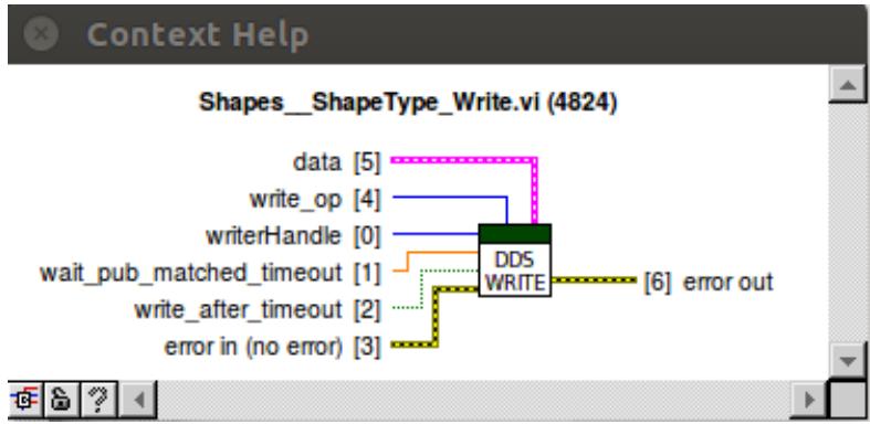
The DDS Write.vi is used to write DDS samples to a specific topic.
![The image displays a block diagram for a LabVIEW function node titled 'Shapes__ShapeType_Write.vi (4824)'.\n\n**Central Block:**\n*   **DDS WRITE** (A green rectangular function node)\n\n**Inputs (connected via wires to the left side of the block):**\n*   **data (5)** (connected by a pink wire)\n*   **write_op (4)** (connected by a blue wire)\n*   **writerHandle (0)** (connected by a blue wire)\n*   **wait_pub_matched_timeout (1)** (connected by an orange wire)\n*   **write_after_timeout (2)** (connected by a green dotted wire)\n*   **error in (no error) (3)** (connected by a yellow dotted wire)\n\n**Output (connected via wire to the right side of the block):**\n*   **(6) error out** (connected by a yellow dotted wire)](.vortex-opensplice-dds-labview-guide/3f5809e26ba5e0fb6db5a505b7343bab5652ad816c30e2811932b3b2321d240a.jpg)

<table><tr><td>Terminal Type</td><td>Optional</td><td>Name</td><td>Description</td><td>Output consumed by</td></tr><tr><td>Input</td><td>no</td><td>writerHandle</td><td>DDS Writer entity instance</td><td></td></tr><tr><td>Input</td><td>yes</td><td>write_op</td><td>write operation: WRITE, DISPOSE, WRITE_DISPOSE Default operation: WRITE</td><td></td></tr><tr><td>Input</td><td>no</td><td>data</td><td>samples LabVIEW cluster</td><td>DDS</td></tr><tr><td>Input</td><td>yes</td><td>wait_pub_matched_timeout</td><td>wait for publication matched timeout (seconds)</td><td></td></tr><tr><td>Input</td><td>yes</td><td>write_after_timeout</td><td>write samples after timeout</td><td></td></tr><tr><td>Input</td><td>yes</td><td>error in (no error)</td><td>Input Error cluster</td><td></td></tr><tr><td>Output</td><td>yes</td><td>error out</td><td>Error out cluster</td><td></td></tr></table>

# 5

# QoS Provider

Each Vortex DDS virtual instrument (VI) has a QoS file uri terminal and a QoS profile terminal. These terminals are used to set the QoS profile. By default, the OSPL default profile is used. In DDS - The Data-Distribution Service (DDS) relies on the usage of QoS. A QoS (Quality of Service) is a set of characteristics that controls some aspect of the behavior of the DDS Service.

Each DDS VI has an associated QoS profile. By default, the OSPL default profile is used. An XML file that specifies QoS profiles can be used to set the QoS of a DDS block.

The following section explains how the QoS is set for a DDS entity using the QoS Provider.

# 5.1 QoS Provider File

Quality of Service for DDS entities is set using XML files based on the XML schema file DDS\_QoSProfile.xsd. These XML files contain one or more QoS profiles for DDS entities.

Note: Sample QoS Profile XML files can be found in the LabVIEW DDS examples directories.

# 5.2 QoS Profile

A QoS profile consists of a name. The file contains QoS elements for one or more DDS entities. A skeleton file without any QoS values is displayed below to show the structure of the file.

```xml
&lt;dds xmlns="http://www.omg.org/dds/" xmlns:xsi="http://www.w3.org/2001/XMLSchema-instance" xsi:schemaLocation="file:DDS_QoSProfile.xsd"&gt;
    &lt;qos_profile name="DDS QoS Profile Name"&gt;
    &lt;datareader_qos&gt;&lt;/datareader_qos&gt;
    &lt;datawriter_qos&gt;&lt;/datawriter_qos&gt;
    &lt;domainparticipant_qos&gt;&lt;/domainparticipant_qos&gt;
    &lt;subscriber_qos&gt;&lt;/subscriber_qos&gt;
    &lt;publisher_qos&gt;&lt;/publisher_qos&gt;
    &lt;topic_qos&gt;&lt;/topic_qos&gt;
    &lt;/qos_profile&gt;
&lt;/dds&gt;
```

# Example: Specify Publisher Partition

The example below specifies the publisher’s partitions as A and B.

```xml
&lt;publisher_qos&gt;
    &lt;partition&gt;
    &lt;name&gt;
    &lt;element&gt;A&lt;/element&gt;
    &lt;element&gt;B&lt;/element&gt;
    &lt;/name&gt;
    &lt;/partition&gt;
&lt;/publisher_qos&gt;
```

# 5.3 Setting QoS Profile in LabVIEW

The QoS Profiles from the XML file can be obtained using the List\_qos\_profiles Tools menu in LabVIEW.

Tools/VortexDDS/List\_qos\_profiles

![Tools Window Help\nMeasurement & Automation Explorer...\nInstrumentation\nProfile\nSecurity\nUser Name...\nInformation on Building Applications\nLLB Manager...\nImport\nShared Variable\nDistributed System Manager\nFind VIs on Disk...\nPrepare Example VIs for NI Example Finder...\nRemote Panel Connection Manager...\nWeb Publishing Tool...\nFind LabVIEW Add-ons...\nVI Package Manager...\nVortexDDS\nAdvanced\nOptions...\nImport_IDL...\nList_qos_profiles...](.vortex-opensplice-dds-labview-guide/2c72edd9fc954fd2630701451f8882daa059e4e1a9a38686f43b1ebd31bb6003.jpg)

# Steps to set the QoS Profile

1. A QoS Provider file can be selected by browsing to the XML file from the List\_qos\_profiles dialog box. Once a valid QoS file is chosen the Available qos profiles table is populated with the list of qos profiles that are available in the QoS XML file. If there are QoS profiles found in the file, then Copy to Clipboard button will be enabled.
2. Select the QoS Profile that you want to use and click on Copy to Clipboard.

![List_qos_profiles\nSelect QoS File\nC:\LabVIEW Test\all_qos.xml\nAvailable qos profiles\nDDS PersistentQosProfile\nDDS DefaultQosProfile\nCopy to Clipboard\nClose](.vortex-opensplice-dds-labview-guide/75144b7117222f827ee97b5dd27e72aec40d4168684f2692951df0b081489bd3.jpg)

3. In your VI, create a String constant and press Ctrl + V. Connect this String constant to the DDS VI qos\_profile terminal. Set the qos\_uri as a LabVIEW control or constant and navigate to the path of the QoS Provider file.

![Based on the image provided, here is the description of the flowchart:\n\n**Labeled Blocks:**\n*   **Top Right:** A teal block labeled 'qos_uri' containing a sub-block with the text '% Path'.\n*   **Bottom Left:** A pink rectangular block labeled 'DDS PersistentQosProfile'.\n*   **Bottom Right:** A square block featuring a blue top section and a green circle in the lower white section.\n\n**Connections:**\n*   A dotted teal line connects the right side of the '% Path' block (within 'qos_uri') to the square block at the bottom right.\n*   A pink wavy line connects the right side of the 'DDS PersistentQosProfile' block to the square block at the bottom right.](.vortex-opensplice-dds-labview-guide/50080182eb233daa1dab632a2c117aabb58d256b7f39170f53f191dae3362584.jpg)

The qos\_profile and qos\_uri are optional terminals. If they are not set then the default QoS settings will be used.

Note: Seeing the QoS Profile in the list only guarantees the QoS Profile exists in the file. It does not mean the qos tag exists for the entity. The user is responsible for verifying the entity qos tag exists in the file.

# 6

# Demo iShapes Example

A simple demo iShapes example is provided to demonstrates the basic capabilities of the LabVIEW DDS integration. It displays DDS communication between LabVIEW and pure DDS applications.

The demo\_ishapes.vi example (LabVIEW application) can be found using the NI Example Finder in LabVIEW:

![NI Example Finder\nBrowse Search\nBrowse according to:\nTask\nDirectory Structure\nDouble-click an example to open it.\nADLINK\nVortexDDS\nDDS_Example_Vls\nDemo_iShapes\nDDS_Data\nShapeType_CicoTable.vi\nShapeType_Read.vi\nShapeType_RegisterTopic.vi\nShapeType_Write.vi\ndemo_ishapes.vi\nApplication Control\nArrays\nBooleans\nChannels\nComparison\nConnectivity\ncontrol\nControls and Indicators\nData Communication\nDesign Patterns\nDialog and User Interface\ndll\nexbins\nExpress Vls\nFile IO\nGraphics and Sound\nVisit ni.com\nfor more examples\nHardware\nFind hardware\nLimit results to hardware\nAdd to Favorites\nSetup...\nHelp\nClose\nInformation\nRequirements](.vortex-opensplice-dds-labview-guide/2ec385d09eebd1a298fcb96a06a7d2e9286dc399e8d372f41e582e91549d838d.jpg)

The demo\_ishapes.exe (DDS application) can be found in the following directory.

OSPL\_HOME/bin/demo\_ishapes.exe

# 6.1 Example Files

An explanation of what each example file does is provided below.

![Demo_iShapes\nDDS_Data\nShapeType.ctl\nShapeType_CicoTable.vi\nShapeType_Read.vi\nShapeType_RegisterTopic.vi\nShapeType_Write.vi\nishape.idl\nishape.idl.xml\nDDS_PersistentQoS_All.xml\nDDS_VolatileQoS_All.xml\ndemo_ishapes.vi](.vortex-opensplice-dds-labview-guide/2cea7910b68db6e4d52bdfa8d81dfbd282737a9cac12bc025cf2e0772bdd8aab.jpg)

# DDS\_Data Folder

This folder contains the idl file and artifacts generated from idlpp process.

# ishape.idl

• Defines the ShapeType in idl
• Used to generate the LabVIEW DDS VIs via idlpp

# ishape.idl.xml

• Defines the topic descriptor from idl file

# ShapeType\_CicoTable.vi

• Defines the copy-in, copy-out table information for mapping IDL to LabVIEW types

# ShapeType.ctl

• Defines a ShapeType cluster in LabVIEW; generated from idlpp
• The ShapeType represents a DDS topic type
• ShapeType specifies 4 properties: color, x, y, shapesize

# ShapeType\_Read.vi

• DDS Read ShapeType samples

# ShapeType\_Write.vi

• DDS Write ShapeType samples

# ShapeType\_Topic.vi

• DDS Register ShapeType topic

# DDS\_PersistentQoS\_All.xml

• XML file that specifies the DDS QoS (quality of service) settings for RegisterTopic

# DDS\_VolatileQoS\_All.xml

• XML file that specifies the DDS QoS (quality of service) settings for Reader and Writer entities

# demo\_ishapes.vi

• Creates a participant on the default DDS domain
• Registers a ShapeType Topic to Read and to Write to one of the three topics: Circle, Square or Triangle

# 6.1. Example Files

• Subscribes to the shape and color from demo\_ishapes.exe DDS application
• As soon as they match, demo\_ishapes.vi publishes to the DDS application and follows the subscribed shape

# 6.2 Steps to run example

# Steps:

1. Open command shell and run script to setup environment variables.

# Linux

• Open a Linux terminal.
• Navigate to directory containing release.com file.
/INSTALLDIR/ADLINK/Vortex\_v2/Device/VortexOpenSplice/6.9.x/HDE/x86\_64.linux
• Run release.com. (Type in “. release.com” at command line.)

# Windows

• Open a command prompt.
• Navigate to directory containing release.bat file.
INSTALLDIR/ADLINK/Vortex\_v2/Device/VortexOpenSplice/6.9.x/HDE/x86\_64.win64
• Run release.bat. (Type in “release.bat” at command line.)

2. Navigate to the directory that contains demo\_ishapes.exe DDS application and run the application using the command shell used in Step 1.

# Linux

/INSTALLDIR/ADLINK/Vortex\_v2/Device/VortexOpenSplice/6.9.x/HDE/x86\_64.linux/bin

• Run demo\_ishapes.exe (Type in “./demo\_ishapes.exe $\& '$ at command line)

# Windows

INSTALLDIR/ADLINK/Vortex\_v2/Device/VortexOpenSplice/6.9.x/HDE/x86\_64.win64/bin

• Run demo\_ishapes.exe (Type in “demo\_ishapes.exe $\& '$ at command line)

3. Start LabVIEW using the SAME command shell used in Step 1. Open the demo\_ishapes.vi using the NI Example Finder in LabVIEW.

NOTE: If LabVIEW and the demo\_ishapes.exe application are NOT started from a command shell with the correct OSPL environment variables set, the example will not work.

4. In the LabVIEW demo\_ishapes.vi application make the following selections:

Read Shape: Circle Track color: GREEN

Write Shape: Triangle Write color: MAGENTA

![demo_ishapes.vi Front Panel\nFile Edit View Project Operate Tools Window Help\n15pt Application Font Search\nRead Shape\nCircle\nWrite Shape\nTriangle\nTrack color\nGREEN\nWrite color\nMAGENTA\nstop\nSTOP](.vortex-opensplice-dds-labview-guide/0d3011426546c13eab21764a9ffcf05c72a62fbfbba6a7165baa7489663d700b.jpg)

5. In the demo\_ishapes.exe DDS application make the following selections:

Shape: Circle Color: Green Click Publish

Shape: Triangle Click Subscribe

![iShapes\nShape: Circle\nColor: Green\nSize:\nSpeed:\nQoS\nPublish\nShape: Triangle\nQoS\nFilter\nSubscribe\nVORTEX OPENSPLICE](.vortex-opensplice-dds-labview-guide/54bb15ca61681b2f3869dc9d5da5ab4a652f9e80e49396b2023e193d01d19784.jpg)

6. Run the LabVIEW demo\_ishapes.vi application
7. To stop the LabVIEW application, click on STOP on the front panel of the demo\_ishapes.vi.

# 6.3 Output

LabVIEW application publishes samples to the DDS application. In the demo\_ishapes.exe application, the Triangle follows the Circle.

![demo_ishapes.vi\nFile Edit View Project Operate Tools Window Help\nRead Shape\nCircle\nWrite Shape\nTriangle\nTrack color\nGREEN\nWrite color\nMAGENTA\nstop\nSTOP\niShapes\nShape: Circle\nColor: Green\nSize:\nSpeed:\nQoS\nPublish\nShape: Triangle\nQoS\nFilter\nSubscribe\nVORTEX OPENSPLICE](.vortex-opensplice-dds-labview-guide/c97d0d62b292d31a6a5dca1c4147f35a6771b01661eff45053d511ad57fc422e.jpg)

# 7

# Contacts & Notices

# 7.1 Contacts

# ADLINK Technology Corporation

400 TradeCenter

Suite 5900

Woburn, MA

01801

USA

Tel: +1 781 569 5819

# ADLINK Technology Limited

The Edge

5th Avenue

Team Valley

Gateshead

NE11 0XA

UK

Tel: +44 (0)191 497 9900

# ADLINK Technology SARL

28 rue Jean Rostand

91400 Orsay

France

Tel: +33 (1) 69 015354

Web: http://ist.adlinktech.com/

Contact: http://ist.adlinktech.com

E-mail: ist\_info@adlinktech.com

LinkedIn: https://www.linkedin.com/company/79111/

Twitter: https://twitter.com/ADLINKTech\_usa

Facebook: https://www.facebook.com/ADLINKTECH

# 7.2 Notices

Copyright © 2018 ADLINK Technology Limited. All rights reserved.

This document may be reproduced in whole but not in part. The information contained in this document is subject to change without notice and is made available in good faith without liability on the part of ADLINK Technology Limited. All trademarks acknowledged.
[🔗 Link to the original document](.vortex-opensplice-dds-labview-guide/vortex-opensplice-dds-labview-guide.pdf)
